EP0704302A1 - Dispositif pour alimenter une plaque d'impression vers le cylindre porte-plaque d'une machine à imprimer - Google Patents
Dispositif pour alimenter une plaque d'impression vers le cylindre porte-plaque d'une machine à imprimer Download PDFInfo
- Publication number
- EP0704302A1 EP0704302A1 EP95113140A EP95113140A EP0704302A1 EP 0704302 A1 EP0704302 A1 EP 0704302A1 EP 95113140 A EP95113140 A EP 95113140A EP 95113140 A EP95113140 A EP 95113140A EP 0704302 A1 EP0704302 A1 EP 0704302A1
- Authority
- EP
- European Patent Office
- Prior art keywords
- protection
- printing
- plate
- support device
- pressure plate
- Prior art date
- Legal status (The legal status is an assumption and is not a legal conclusion. Google has not performed a legal analysis and makes no representation as to the accuracy of the status listed.)
- Granted
Links
Images


Classifications
-
- B—PERFORMING OPERATIONS; TRANSPORTING
- B41—PRINTING; LINING MACHINES; TYPEWRITERS; STAMPS
- B41F—PRINTING MACHINES OR PRESSES
- B41F27/00—Devices for attaching printing elements or formes to supports
- B41F27/12—Devices for attaching printing elements or formes to supports for attaching flexible printing formes
- B41F27/1206—Feeding to or removing from the forme cylinder
Definitions
- the invention relates to a device for feeding a printing plate to the plate cylinder of a printing press according to the preamble of claim 1.
- a printing plate to be fed to the plate cylinder is first fixed with its start of printing in a corresponding clamping rail and then drawn up by rotating the plate cylinder about it.
- automated clamping devices have become known in which the fastening (clamping) and also the tensioning of the printing plate is carried out automatically by means of remotely controllable adjusting means.
- So-called fully automatic printing plate changers have also become known, in which the entire printing plate changing process takes place without any handling effort. Such devices are expensive and prone to failure.
- So-called semi-automatic pressure plate changers represent a good compromise in terms of comfort due to automation on the one hand and the effort caused by additional components on the other hand, in which clamping and clamping is carried out by remote-controlled actuating means, the removal of an old, used pressure plate and the feeding of a new pressure plate from or to the plate cylinder but done by an operator.
- Such a device is known for example from DE 4 214 049 C2, in which a vertically displaceable and at the same time pivotably mounted in front of printing unit cylinders Protection has holding devices for the new pressure plate to be fed, the holding devices consisting on the one hand of a rotatably mounted roller on the lower area of the protection and one or more suction cups in the upper area of the protection.
- the plate is inserted by hand into the corresponding clamping device of the plate cylinder and then clamped. By rotating the plate cylinder forward, the printing plate is then pulled onto it.
- this known, partially automated printing plate feed device provides that the printing plates to be used are bent at their ends. So that the suction cup or suction cups release the pressure plate shortly before reaching the bend, provision is made for ventilation bores to be provided in the pressure plate. After the end of the pressure plate has been released by the suction cup or cups, the pressure plate is now only guided through the roll, so that its end sags and, under certain circumstances, is damaged by this movement on the printing side.
- the openings of the printing plate to be provided at the end of the printing thereof are to be regarded as disadvantageous. Contamination of the suction cups also significantly reduces their holding power.
- the sheet-fed offset printing machine with the designation R 700 from MAN Roland Druckmaschinen AG has made known a protection that can be moved vertically in front of the printing unit cylinders, this protection having two stops on its lower edge, on which a new printing plate can be provided on the delivery side.
- the protection is moved to an upper position and the used printing plate is then removed from the plate cylinder by hand.
- the new pressure plate provided on the guard is also removed from the stops by hand and inserted into the clamping rail at the start of printing.
- it must be ensured by holding the plate at its end of printing that it cannot be damaged on any objects.
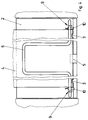
- Figures 1 to 3 show the delivery side of a printing unit with plate cylinder 1 arranged therein.
- the delivery side of the printing unit is protected by a vertically displaceable protection 2.
- the protection 2 is articulated with a straight guide on the side frame walls of the printing unit.
- Figure 1 shows the operating position of the protection 2, in which it is in the lowest position and thus flatly covers the danger point of the plate cylinder 1 and the blanket cylinder located below. Above the end of protection 2 there are further contaminations, not shown. These cover the delivery side of the inking unit.
- two stops 3 are attached, which are designed in a hook-like manner pointing upwards (see also FIGS. 4 and 6).
- a new pressure plate 4 to be supplied can be provided on these stops 3 in the basic position of the protection 2 (FIG. 1).
- Figure 2 shows the protection with the printing plate 4 thereon in the raised position, in which the plate cylinder 1 and the blanket cylinder located below are accessible.
- the support device 6 which is connected to the protection 2 in the lower region via a joint 9, in one vertical position swiveled.
- the support device 6 is designed as a substantially U-shaped bracket made of round material and connected to the guard 2 via two joints 9 in the lower region of the guard 2.
- the pivotable articulation of the support device 6 with respect to the protection 2 allows the pressure plate 4 to be supplied to be fed in when the protection 2 is pushed up in a plane of the clamping rail 7 of the plate cylinder 1 which extends obliquely to the direction of extension of the protection 2.
- the support device 6 is brought out of the vertical basic position into the pivoted-off position shown in FIG. 3 and then the pressure plate 4 taken from the stops 3 is inserted into the clamping gap of the clamping rail 7. The pressure plate leading edge is then clamped either manually or remotely at the push of a button.
- the tube of the U-shaped bracket forming the support device 6 is provided with brushes 8 on the side facing the pressure plate 4 (FIG. 7). These brushes 8 are recognizably embedded in a groove machined into the bracket of the support device 6.
- a side stop 10 is preferably provided on both sides at the lower end of the protection 2, by means of which the pressure plate 4 has at least a rough alignment in the side register direction with respect to the plate cylinder 1 both when setting the stops 3 and when removing the stops 3 and the insertion into the clamping rail 7 of the plate cylinder 1 experiences.
- these side stops 10 are essentially designed as angle plates.
- At least one of the side stops 10 is movably attached to the guard 2 in order to adapt to different plate formats in the axial direction of the plate cylinder 1.
- FIGS. 5 and 6 show a joint 9 and the means assigned to the joint 9 for limiting the pivoting movement of the support device 6 according to the invention.
- the horizontally angled legs of the essentially U-shaped bracket each end at one on the protection 2 attached block 11.
- the two ends of the tube of the support device 6 each have a plate 12, in which a hole is machined centrally to the axis of the tube of the support device 6, into which a pin 13 inserted in the block 11 is immersed. Pin 13 thus forms the joint 9 of the support device 6 in connection with the bore in the plate 12.
- FIG. 5 shows a view of the joint 9 on the left in FIG. 4.
- FIG. 5 A-A is a view shown in FIG. 6, which shows the joint 9 with the lower part of the protection 2.
- the part of the plate 12 pointing to the protection 2 and fixedly attached to the support device 6 is provided there with an arcuate slot 14 through which the shaft of a screw 15 screwed into the block 11 engages.
- the shaft of the screw 15 thus defines, in conjunction with the dimensions of the elongated hole 14, the possible pivoting path between the basic and working positions of the support device 6 according to the invention.
- FIG. 6 shows the position of the plate 12 and thus of the support device 6 according to FIGS. 1 and 2, that is to say the basic position of the support device 6 again.
- FIG. 5 shows that a washer 17, which is supported on the head of the screw 15, presses a disk 17 against which the flanks of the plate 12 adjacent to the elongated hole 14 are pressed. It is thereby achieved that the support device 6 assumes a stable position, in particular in the basic position shown in FIGS. 1 and 2, and furthermore can also be pivoted into any intermediate position according to the positions shown in FIGS. 2 and 3.
- the joint 9 described above with reference to FIGS. 5 and 6 is attached outside the format limits of a largest printing plate 4 to be processed in mirror image to one another in the lower region of the protection 2 (FIG. 4).
Landscapes
- Supply, Installation And Extraction Of Printed Sheets Or Plates (AREA)
- Sheets, Magazines, And Separation Thereof (AREA)
Applications Claiming Priority (2)
| Application Number | Priority Date | Filing Date | Title |
|---|---|---|---|
| DE9415751U | 1994-09-29 | ||
| DE9415751U DE9415751U1 (de) | 1994-09-29 | 1994-09-29 | Vorrichtung zum Zuführen einer Druckplatte zum Plattenzylinder einer Druckmaschine |
Publications (2)
| Publication Number | Publication Date |
|---|---|
| EP0704302A1 true EP0704302A1 (fr) | 1996-04-03 |
| EP0704302B1 EP0704302B1 (fr) | 1998-01-28 |
Family
ID=6914309
Family Applications (1)
| Application Number | Title | Priority Date | Filing Date |
|---|---|---|---|
| EP95113140A Expired - Lifetime EP0704302B1 (fr) | 1994-09-29 | 1995-08-22 | Dispositif pour alimenter une plaque d'impression vers le cylindre porte-plaque d'une machine à imprimer |
Country Status (5)
| Country | Link |
|---|---|
| US (1) | US5575212A (fr) |
| EP (1) | EP0704302B1 (fr) |
| JP (1) | JP2929521B2 (fr) |
| AT (1) | ATE162760T1 (fr) |
| DE (2) | DE9415751U1 (fr) |
Cited By (1)
| Publication number | Priority date | Publication date | Assignee | Title |
|---|---|---|---|---|
| WO2004020202A2 (fr) * | 2002-08-21 | 2004-03-11 | Koenig & Bauer Aktiengesellschaft | Dispositifs permettant de monter un bloc d'impression sur un cylindre grave d'une machine a imprimer |
Families Citing this family (8)
| Publication number | Priority date | Publication date | Assignee | Title |
|---|---|---|---|---|
| US6113346A (en) | 1996-07-31 | 2000-09-05 | Agfa Corporation | Method for loading and unloading a supply of plates in an automated plate handler |
| DE19803726B4 (de) * | 1998-01-30 | 2007-12-27 | Heidelberger Druckmaschinen Ag | Druckwerk mit einem Druckwerksschutz und einer verstellbaren Aufhängung für den Druckwerksschutz |
| US6951172B2 (en) * | 1998-03-31 | 2005-10-04 | Heidelberger Druckmaschinen Ag | Accessory for a printing unit |
| DE10139292A1 (de) * | 2000-09-13 | 2002-03-21 | Heidelberger Druckmasch Ag | Vorrichtung zum Halten und Zuführen einer Druckplatte zu einem Druckzylinder einer Druckmaschine |
| JP4603811B2 (ja) * | 2003-07-25 | 2010-12-22 | ハイデルベルガー ドルツクマシーネン アクチエンゲゼルシヤフト | 印刷機に版板を供給し且つ/又は排出するための装置 |
| DE102007010762A1 (de) * | 2007-03-06 | 2008-09-11 | Man Roland Druckmaschinen Ag | Druckeinheit einer Rollendruckmaschine |
| DE102008048734B4 (de) | 2007-10-18 | 2022-02-24 | Heidelberger Druckmaschinen Intellectual Property Ag & Co. Kg | Vorrichtung zur Aufnahme von Druckplatten |
| DE102008049475A1 (de) * | 2007-10-18 | 2009-04-23 | Heidelberger Druckmaschinen Ag | Vorrichtung zum Zuführen von Druckplatten zu einem Plattenzylinder einer Druckmaschine |
Citations (2)
| Publication number | Priority date | Publication date | Assignee | Title |
|---|---|---|---|---|
| EP0567754A1 (fr) * | 1992-04-29 | 1993-11-03 | Heidelberger Druckmaschinen Aktiengesellschaft | Dispositif pour amener une plaque d'impression à un cylindre de plaque d'une machine à imprimer |
| EP0655330A1 (fr) * | 1993-11-26 | 1995-05-31 | Sakurai Graphic Systems Corp. | Dispositif de chargement de cliché dans une machine à imprimer |
Family Cites Families (10)
| Publication number | Priority date | Publication date | Assignee | Title |
|---|---|---|---|---|
| JP2844539B2 (ja) * | 1989-12-15 | 1999-01-06 | 株式会社小森コーポレーション | 印刷機の刷版保持装置 |
| JP2722022B2 (ja) * | 1991-03-14 | 1998-03-04 | 株式会社小森コーポレーション | 版胴への刷版装着装置 |
| DE4121992A1 (de) * | 1991-07-03 | 1993-01-07 | Heidelberger Druckmasch Ag | Absturzsicherung an einem podest einer druckmaschine |
| ATE139481T1 (de) * | 1991-08-31 | 1996-07-15 | Heidelberger Druckmasch Ag | Vorrichtung zur positionierung eines dem automatischen druckplattenwechsel dienenden magazins |
| DE4224832C3 (de) * | 1991-08-31 | 1999-06-24 | Heidelberger Druckmasch Ag | Vorrichtung zur Positionierung eines dem automatischen Druckplattenwechsel dienenden Magazins |
| DE4140413C2 (de) * | 1991-12-07 | 1995-03-16 | Roland Man Druckmasch | Vorrichtung zum Wechseln von Druckplatten bei Offsetdruckmaschinen |
| DE4214047A1 (de) * | 1992-04-29 | 1993-11-04 | Heidelberger Druckmasch Ag | Halteeinrichtung fuer eine zu verschiebende platte |
| DE4215969C2 (de) * | 1992-05-18 | 1994-10-13 | Roland Man Druckmasch | Vorrichtung zum Zuführen von Druckplatten auf den Plattenzylinder von Druckmaschinen, insbesondere Bogenoffsetdruckmaschinen |
| DE4226780C2 (de) * | 1992-08-13 | 1994-12-01 | Roland Man Druckmasch | Vorrichtung zur Kontrolle der registergerechten Anlage einer Druckplatte auf dem Plattenzylinder von Druckmaschinen, insbesondere Bogenoffsetdruckmaschinen |
| DE4327013C1 (de) * | 1993-08-12 | 1995-01-12 | Heidelberger Druckmasch Ag | Druckplatten-Kassette für ein Magazin |
-
1994
- 1994-09-29 DE DE9415751U patent/DE9415751U1/de not_active Expired - Lifetime
-
1995
- 1995-08-22 EP EP95113140A patent/EP0704302B1/fr not_active Expired - Lifetime
- 1995-08-22 DE DE59501359T patent/DE59501359D1/de not_active Expired - Fee Related
- 1995-08-22 AT AT95113140T patent/ATE162760T1/de not_active IP Right Cessation
- 1995-09-25 JP JP7246497A patent/JP2929521B2/ja not_active Expired - Fee Related
- 1995-09-29 US US08/536,828 patent/US5575212A/en not_active Expired - Fee Related
Patent Citations (3)
| Publication number | Priority date | Publication date | Assignee | Title |
|---|---|---|---|---|
| EP0567754A1 (fr) * | 1992-04-29 | 1993-11-03 | Heidelberger Druckmaschinen Aktiengesellschaft | Dispositif pour amener une plaque d'impression à un cylindre de plaque d'une machine à imprimer |
| DE4214049C2 (fr) | 1992-04-29 | 1994-04-21 | Heidelberger Druckmaschinen Ag, 69115 Heidelberg, De | |
| EP0655330A1 (fr) * | 1993-11-26 | 1995-05-31 | Sakurai Graphic Systems Corp. | Dispositif de chargement de cliché dans une machine à imprimer |
Cited By (2)
| Publication number | Priority date | Publication date | Assignee | Title |
|---|---|---|---|---|
| WO2004020202A2 (fr) * | 2002-08-21 | 2004-03-11 | Koenig & Bauer Aktiengesellschaft | Dispositifs permettant de monter un bloc d'impression sur un cylindre grave d'une machine a imprimer |
| WO2004020202A3 (fr) * | 2002-08-21 | 2004-07-29 | Koenig & Bauer Ag | Dispositifs permettant de monter un bloc d'impression sur un cylindre grave d'une machine a imprimer |
Also Published As
| Publication number | Publication date |
|---|---|
| DE59501359D1 (de) | 1998-03-05 |
| ATE162760T1 (de) | 1998-02-15 |
| DE9415751U1 (de) | 1994-11-17 |
| EP0704302B1 (fr) | 1998-01-28 |
| US5575212A (en) | 1996-11-19 |
| JPH08108526A (ja) | 1996-04-30 |
| JP2929521B2 (ja) | 1999-08-03 |
Similar Documents
| Publication | Publication Date | Title |
|---|---|---|
| EP0667237B1 (fr) | Dispositif pour échanger automatiquement des plaques d'impression | |
| EP0654349B1 (fr) | Magasin pour l'échange automatique de plaques d'impression dans une machine à imprimer | |
| DE4215969C2 (de) | Vorrichtung zum Zuführen von Druckplatten auf den Plattenzylinder von Druckmaschinen, insbesondere Bogenoffsetdruckmaschinen | |
| EP0433798B1 (fr) | Dispositif de changement d'une plaque d'impression | |
| EP0949071B1 (fr) | Dispositif auxiliaire pour une machine d'impression | |
| EP0740608B1 (fr) | Dispositif de montage, de demontage et de transport d'objets courbes faciles a plier et pourvus de rebords de suspension | |
| EP0704302B1 (fr) | Dispositif pour alimenter une plaque d'impression vers le cylindre porte-plaque d'une machine à imprimer | |
| EP0740607B1 (fr) | Dispositif pour le montage, le demontage et le transport d'objets courbes facilement pliables pourvus d'aretes d'accrochage | |
| DE4322027A1 (de) | Vorrichtung zum automatischen Wechseln einer Druckplatte | |
| EP0673765A1 (fr) | Support pour un dispositif de protection des cylindres d'impression d'une machine d'impression | |
| EP0727311A1 (fr) | Dispositif pour échanger des plaques d'impression | |
| EP0419937A2 (fr) | Dispositif de raclage | |
| DE4030864C2 (fr) | ||
| EP1530514B1 (fr) | Procede permettant de monter un habillage sur le cylindre d'une machine a imprimer | |
| EP0186143A2 (fr) | Appareil pour appliquer des feuilles de revêtement sur des éléments en forme de plaques ou analogues | |
| EP1256449B1 (fr) | Imprimante avec un cylindre de plaque et avec une barre d'insertion | |
| DE4444629C1 (de) | Aufnahmebehälter für einen Druckplattenwechsler einer Druckmaschine | |
| DE4134365C2 (de) | Einrichtung zum Schnellaufspannen von Druckplatten | |
| DE4344090A1 (de) | Einrichtung zum automatischen Zu- und Abführen von Druckplatten | |
| DE29717139U1 (de) | Vorrichtung zum Dekorieren von flachen selbsttragenden Objekten | |
| EP2581226B1 (fr) | Presse et procédé de positionnement d'au moins un cylindre d'encrage | |
| EP0875378A1 (fr) | Dispositif de serrage | |
| DE29912718U1 (de) | Band-Klebeautomat | |
| DE9203177U1 (de) | Reinigungsvorrichtung für eine automatische Druckmaschine | |
| DE3202838A1 (de) | Handhabungseinrichtung fuer werkstuecke |
Legal Events
| Date | Code | Title | Description |
|---|---|---|---|
| PUAI | Public reference made under article 153(3) epc to a published international application that has entered the european phase |
Free format text: ORIGINAL CODE: 0009012 |
|
| 17P | Request for examination filed |
Effective date: 19950914 |
|
| AK | Designated contracting states |
Kind code of ref document: A1 Designated state(s): AT BE CH DE FR GB IT LI NL |
|
| K1C1 | Correction of patent application (title page) published |
Effective date: 19960403 |
|
| GRAG | Despatch of communication of intention to grant |
Free format text: ORIGINAL CODE: EPIDOS AGRA |
|
| GRAG | Despatch of communication of intention to grant |
Free format text: ORIGINAL CODE: EPIDOS AGRA |
|
| GRAH | Despatch of communication of intention to grant a patent |
Free format text: ORIGINAL CODE: EPIDOS IGRA |
|
| GRAH | Despatch of communication of intention to grant a patent |
Free format text: ORIGINAL CODE: EPIDOS IGRA |
|
| 17Q | First examination report despatched |
Effective date: 19970630 |
|
| GRAA | (expected) grant |
Free format text: ORIGINAL CODE: 0009210 |
|
| AK | Designated contracting states |
Kind code of ref document: B1 Designated state(s): AT BE CH DE FR GB IT LI NL |
|
| PG25 | Lapsed in a contracting state [announced via postgrant information from national office to epo] |
Ref country code: NL Free format text: LAPSE BECAUSE OF FAILURE TO SUBMIT A TRANSLATION OF THE DESCRIPTION OR TO PAY THE FEE WITHIN THE PRESCRIBED TIME-LIMIT Effective date: 19980128 Ref country code: IT Free format text: LAPSE BECAUSE OF FAILURE TO SUBMIT A TRANSLATION OF THE DESCRIPTION OR TO PAY THE FEE WITHIN THE PRESCRIBED TIME-LIMIT;WARNING: LAPSES OF ITALIAN PATENTS WITH EFFECTIVE DATE BEFORE 2007 MAY HAVE OCCURRED AT ANY TIME BEFORE 2007. THE CORRECT EFFECTIVE DATE MAY BE DIFFERENT FROM THE ONE RECORDED. Effective date: 19980128 |
|
| REF | Corresponds to: |
Ref document number: 162760 Country of ref document: AT Date of ref document: 19980215 Kind code of ref document: T |
|
| REG | Reference to a national code |
Ref country code: CH Ref legal event code: NV Representative=s name: E. BLUM & CO. PATENTANWAELTE Ref country code: CH Ref legal event code: EP |
|
| ET | Fr: translation filed | ||
| GBT | Gb: translation of ep patent filed (gb section 77(6)(a)/1977) |
Effective date: 19980129 |
|
| REF | Corresponds to: |
Ref document number: 59501359 Country of ref document: DE Date of ref document: 19980305 |
|
| NLV1 | Nl: lapsed or annulled due to failure to fulfill the requirements of art. 29p and 29m of the patents act | ||
| PG25 | Lapsed in a contracting state [announced via postgrant information from national office to epo] |
Ref country code: BE Free format text: LAPSE BECAUSE OF NON-PAYMENT OF DUE FEES Effective date: 19980831 |
|
| PLBE | No opposition filed within time limit |
Free format text: ORIGINAL CODE: 0009261 |
|
| STAA | Information on the status of an ep patent application or granted ep patent |
Free format text: STATUS: NO OPPOSITION FILED WITHIN TIME LIMIT |
|
| 26N | No opposition filed | ||
| BERE | Be: lapsed |
Owner name: MAN ROLAND DRUCKMASCHINEN A.G. Effective date: 19980831 |
|
| PGFP | Annual fee paid to national office [announced via postgrant information from national office to epo] |
Ref country code: GB Payment date: 20010713 Year of fee payment: 7 |
|
| PGFP | Annual fee paid to national office [announced via postgrant information from national office to epo] |
Ref country code: CH Payment date: 20010716 Year of fee payment: 7 |
|
| PGFP | Annual fee paid to national office [announced via postgrant information from national office to epo] |
Ref country code: AT Payment date: 20010725 Year of fee payment: 7 |
|
| REG | Reference to a national code |
Ref country code: GB Ref legal event code: IF02 |
|
| PGFP | Annual fee paid to national office [announced via postgrant information from national office to epo] |
Ref country code: FR Payment date: 20020812 Year of fee payment: 8 |
|
| PG25 | Lapsed in a contracting state [announced via postgrant information from national office to epo] |
Ref country code: GB Free format text: LAPSE BECAUSE OF NON-PAYMENT OF DUE FEES Effective date: 20020822 Ref country code: AT Free format text: LAPSE BECAUSE OF NON-PAYMENT OF DUE FEES Effective date: 20020822 |
|
| PG25 | Lapsed in a contracting state [announced via postgrant information from national office to epo] |
Ref country code: LI Free format text: LAPSE BECAUSE OF NON-PAYMENT OF DUE FEES Effective date: 20020831 Ref country code: CH Free format text: LAPSE BECAUSE OF NON-PAYMENT OF DUE FEES Effective date: 20020831 |
|
| REG | Reference to a national code |
Ref country code: CH Ref legal event code: PL |
|
| GBPC | Gb: european patent ceased through non-payment of renewal fee |
Effective date: 20020822 |
|
| PG25 | Lapsed in a contracting state [announced via postgrant information from national office to epo] |
Ref country code: FR Free format text: LAPSE BECAUSE OF NON-PAYMENT OF DUE FEES Effective date: 20040430 |
|
| REG | Reference to a national code |
Ref country code: FR Ref legal event code: ST |
|
| PGFP | Annual fee paid to national office [announced via postgrant information from national office to epo] |
Ref country code: DE Payment date: 20070822 Year of fee payment: 13 |
|
| PG25 | Lapsed in a contracting state [announced via postgrant information from national office to epo] |
Ref country code: DE Free format text: LAPSE BECAUSE OF NON-PAYMENT OF DUE FEES Effective date: 20090303 |