EP0308468B1 - Pompe hydraulique monopiston a commande manuelle - Google Patents
Pompe hydraulique monopiston a commande manuelle Download PDFInfo
- Publication number
- EP0308468B1 EP0308468B1 EP88903168A EP88903168A EP0308468B1 EP 0308468 B1 EP0308468 B1 EP 0308468B1 EP 88903168 A EP88903168 A EP 88903168A EP 88903168 A EP88903168 A EP 88903168A EP 0308468 B1 EP0308468 B1 EP 0308468B1
- Authority
- EP
- European Patent Office
- Prior art keywords
- piston
- bore
- channel
- chamber
- restrictor
- Prior art date
- Legal status (The legal status is an assumption and is not a legal conclusion. Google has not performed a legal analysis and makes no representation as to the accuracy of the status listed.)
- Expired - Lifetime
Links
Images
Classifications
-
- F—MECHANICAL ENGINEERING; LIGHTING; HEATING; WEAPONS; BLASTING
- F04—POSITIVE - DISPLACEMENT MACHINES FOR LIQUIDS; PUMPS FOR LIQUIDS OR ELASTIC FLUIDS
- F04B—POSITIVE-DISPLACEMENT MACHINES FOR LIQUIDS; PUMPS
- F04B53/00—Component parts, details or accessories not provided for in, or of interest apart from, groups F04B1/00 - F04B23/00 or F04B39/00 - F04B47/00
- F04B53/10—Valves; Arrangement of valves
- F04B53/12—Valves; Arrangement of valves arranged in or on pistons
- F04B53/125—Reciprocating valves
- F04B53/129—Poppet valves
Definitions
- the invention relates to a hydraulic single-piston pump, which has the features of the preamble of claim 1.
- the invention has for its object to improve a single-piston pump of the type mentioned. This object is achieved by a pump with the features of claim 1.
- the throttle bore of the second channel not only reduces costs. It also leads to less susceptibility to faults even under harsh operating conditions and allows a smaller overall height. Above all, the throttle bore means that the force to be applied during the working stroke depends on the actuation speed, that is to say the pump speed.
- the actuation speed that is to say the pump speed.
- the user can, in the pump according to the invention, independently of the pressure in the piston chamber, the actuating force to be exerted on the piston within the range defined by the full piston cross section and the reduced piston cross section Adapt borders to your possibilities.
- any load regardless of its size, can be raised with fewer pumping cycles than with a lower pumping speed by means of a higher pumping speed, which, however, also requires more effort.
- Another advantage of the solution according to the invention is that during the working stroke in the rod space no negative pressure can arise which, if the rod seal is not fully functional, results in air being sucked in.
- the second channel In the case of a relatively short length of the second channel, this can be designed as a throttle bore over its entire length. As a rule, however, the second channel will be longer than the required length of the throttle section. You can then run the second channel with the exception of the portion forming the throttle bore with a larger diameter.
- two throttle bores which follow one another at a distance can also be provided in the course of the second channel. These two throttle bores are then connected to one another by a channel section with a larger diameter.
- This embodiment has advantages in terms of production technology and flow technology. For example, for reasons of production costs, it is advantageous if one of the two throttle bores is arranged coaxially with the section of the second channel which is larger in diameter.
- the second throttle bore can also be coaxial, but can also run at an angle to this channel section.
- the channel section with a larger diameter penetrates from the end face of the piston facing the piston chamber.
- One throttle bore can connect coaxially to the end in the piston.
- the other throttle bore can either be provided in a closure body which closes the beginning of this channel section penetrating from the piston end face. But you can also let the second throttle bore open into the channel between the closure body and the other throttle section, for example from the outer surface of the piston.
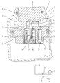
- the single figure shows an incompletely shown longitudinal section of the embodiment.
- a hand-operated hydraulic piston pump designated as a whole by 1, has a cylinder 2, in which a piston, designated as a whole by 3, is arranged so as to be longitudinally displaceable.
- the piston 3 is provided at one end with a piston rod 4 which is guided so as to be longitudinally displaceable in a guide 2 'which adjoins the end of the cylinder 2 which delimits the rod chamber 5.
- the sealing of the piston rod 4 in the guide 2 ' is indicated by an O-ring 6.
- the piston chamber 7, which is separated from the rod chamber 5 by the piston 3, is connected to a tank 10 via a connecting line 8 and a first check valve 9, and to a working cylinder 12 via a second check valve 11, which is, for example, the working cylinder of a lifting truck.
- the piston seal on the inside wall of the cylinder is an O-ring 13 formed, which lies in an annular groove of the piston 3.
- the piston has a central extension 3 ′ on the side delimiting the piston chamber 7, the outer diameter of which is smaller than the section adapted to the inner diameter of the cylinder 3, but larger than the diameter of the piston rod 4.
- This valve body 15 is arranged at one end of a guide sleeve 16 which is longitudinally displaceable on a guide pin 17 which projects from a perforated plate 18 which is screwed into the initial section of the blind hole 14.
- a helical compression spring 19 surrounding the guide sleeve 16 and the guide pin 17 is supported on the perforated plate 18 and loads the valve body 15 with the required force.
- a transverse bore 20 opens into the end section of the blind bore 14 located in the piston rod 4 and penetrates from an annular groove 21 provided at the transition from the piston rod 4 to the piston 3 into the piston rod 4 at right angles to its longitudinal axis.
- the preload of the helical compression spring 19 is selected such that the check valve opens and the hydraulic fluid flows into the piston chamber 7 even at a relatively low overpressure in the rod chamber 5 during the piston return stroke.
- a bore which penetrates from the end face of the piston 3 which delimits the piston chamber 7 22 is provided, which ends at a distance from the ring throat 21.
- the diameter of the bore 22 is, as the figure shows, much larger than that of the first throttle bore 23. Its axial length is also a multiple of the axial length of the first throttle bore 23.
- the beginning of the bore 22 is sealed by a closure body 24, at which in the exemplary embodiment is a ball pressed into the initial section of the bore 22.
- a second throttle bore 25 opens into the bore 22 at right angles to its longitudinal extension, which second bore opens into the lateral surface of the extension 3 '.
- the cross section of the two throttle bores 23 and 25 and their length are chosen so that during a working stroke of the piston 3 at a relatively high speed, the throttling effect is so strong that only a little hydraulic fluid can pass from the piston chamber 7 into the rod chamber 5, that on the other hand at relatively low speed of movement of the piston 3, there is largely pressure equalization between the piston chamber 7 and the rod chamber 5.
- the diameter of the bore 22 is substantially larger than that of the throttle bore 23 and 25, so that the section lying between the two throttle bores is not involved in the throttle effect.
Landscapes
- Engineering & Computer Science (AREA)
- Mechanical Engineering (AREA)
- General Engineering & Computer Science (AREA)
- Actuator (AREA)
- Details Of Reciprocating Pumps (AREA)
- Reciprocating Pumps (AREA)
Abstract
Claims (7)
Applications Claiming Priority (2)
| Application Number | Priority Date | Filing Date | Title |
|---|---|---|---|
| DE3710919A DE3710919C1 (de) | 1987-04-01 | 1987-04-01 | Hydraulische Einkolbenpumpe fuer eine Handbetaetigung |
| DE3710919 | 1987-04-01 |
Publications (2)
| Publication Number | Publication Date |
|---|---|
| EP0308468A1 EP0308468A1 (fr) | 1989-03-29 |
| EP0308468B1 true EP0308468B1 (fr) | 1990-08-22 |
Family
ID=6324601
Family Applications (1)
| Application Number | Title | Priority Date | Filing Date |
|---|---|---|---|
| EP88903168A Expired - Lifetime EP0308468B1 (fr) | 1987-04-01 | 1988-03-31 | Pompe hydraulique monopiston a commande manuelle |
Country Status (5)
| Country | Link |
|---|---|
| US (1) | US4923373A (fr) |
| EP (1) | EP0308468B1 (fr) |
| JP (1) | JPH01502840A (fr) |
| DE (1) | DE3710919C1 (fr) |
| WO (1) | WO1988007495A1 (fr) |
Families Citing this family (9)
| Publication number | Priority date | Publication date | Assignee | Title |
|---|---|---|---|---|
| TW232759B (fr) * | 1992-03-16 | 1994-10-21 | Wagner Spray Tech Corp | |
| US5318139A (en) * | 1993-04-29 | 1994-06-07 | Evans Robert W | Reduced waiting time hydraulic drilling jar |
| US5624001A (en) | 1995-06-07 | 1997-04-29 | Dailey Petroleum Services Corp | Mechanical-hydraulic double-acting drilling jar |
| DE19848035A1 (de) * | 1998-10-17 | 2000-04-20 | Bosch Gmbh Robert | Radialkolbenpumpe für Kraftstoffhochdruckerzeugung |
| US6290004B1 (en) | 1999-09-02 | 2001-09-18 | Robert W. Evans | Hydraulic jar |
| US6481495B1 (en) | 2000-09-25 | 2002-11-19 | Robert W. Evans | Downhole tool with electrical conductor |
| DE102004028999A1 (de) * | 2004-06-16 | 2006-01-05 | Robert Bosch Gmbh | Hochdruckpumpe für eine Kraftstoffeinspritzeinrichtung einer Brennkraftmaschine |
| US9630469B2 (en) * | 2010-10-18 | 2017-04-25 | Firestone Industrial Products Company, Llc | Gas spring and gas damper assembly and method |
| DE102018213997A1 (de) * | 2018-08-20 | 2020-02-20 | Robert Bosch Gmbh | Pumpenanordnung |
Family Cites Families (6)
| Publication number | Priority date | Publication date | Assignee | Title |
|---|---|---|---|---|
| US3112705A (en) * | 1961-10-05 | 1963-12-03 | Jane Wallen | Two-speed hydraulic pumps |
| DE2131802C3 (de) * | 1971-06-26 | 1974-05-16 | Josef Bautz Gmbh, 7968 Saulgau | Einrichtung zum Ablassen der Hubflüssigkeit aus dem Druckraum einer Schubkolbenpumpe |
| DE2551336B2 (de) * | 1975-11-15 | 1979-08-30 | Jungheinrich Unternehmensverwaltung Kg, 2000 Hamburg | Hydraulische Hubeinrichtung mit einer Lasthub-Zylinder-Kolbeneinheit |
| US4357798A (en) * | 1980-03-13 | 1982-11-09 | Michael Hung | Rapid actuating device of hydraulic actuator |
| US4520908A (en) * | 1983-11-10 | 1985-06-04 | General Motors Corporation | Pressure balanced valve for adjustable hydraulic damper |
| FR2560938A1 (fr) * | 1984-03-12 | 1985-09-13 | Antkowiak Stephane | Verin hydraulique actionne par une pompe a main incorporee ou non au verin |
-
1987
- 1987-04-01 DE DE3710919A patent/DE3710919C1/de not_active Expired
-
1988
- 1988-03-31 WO PCT/DE1988/000211 patent/WO1988007495A1/fr active IP Right Grant
- 1988-03-31 EP EP88903168A patent/EP0308468B1/fr not_active Expired - Lifetime
- 1988-03-31 US US07/276,321 patent/US4923373A/en not_active Expired - Fee Related
- 1988-03-31 JP JP63503012A patent/JPH01502840A/ja active Pending
Also Published As
| Publication number | Publication date |
|---|---|
| WO1988007495A1 (fr) | 1988-10-06 |
| EP0308468A1 (fr) | 1989-03-29 |
| JPH01502840A (ja) | 1989-09-28 |
| US4923373A (en) | 1990-05-08 |
| DE3710919C1 (de) | 1988-06-30 |
Similar Documents
| Publication | Publication Date | Title |
|---|---|---|
| EP0565982A1 (fr) | Agencement de soupape | |
| DE2109378C3 (de) | Rückschlagventil mit zusätzlicher Betätigung | |
| EP0308468B1 (fr) | Pompe hydraulique monopiston a commande manuelle | |
| DE2945911C2 (fr) | ||
| DE19716042C1 (de) | Hydraulische Steuervorrichtung für wenigstens ein Hubventil | |
| EP0863342B1 (fr) | Soupape de commande de pression | |
| DE4234626C2 (de) | Druckgesteuertes Ventil | |
| DE970609C (de) | Ventilanordnung fuer hydraulische Anlagen | |
| DE2322354A1 (de) | Arbeitszylinder, insbesondere hydraulikzylinder, mit einer daempfungseinrichtung fuer das ende des arbeitshubes des kolbens | |
| EP0051728A1 (fr) | Dispositif de commande pour un vérin hydraulique | |
| DE2716694C2 (fr) | ||
| DE2929232C2 (fr) | ||
| DE874277C (de) | Hydraulische Hubvorrichtung fuer Stapelgeraete | |
| DE3135098A1 (de) | Ventilaufbau, umfassend ein pumpensteuer- bzw. -regelventil und eine entlastungsanordnung | |
| DE3737579A1 (de) | Anhaengerbremsventil | |
| DE3006530A1 (de) | Hydraulisches blockier- oder halteventil | |
| DE2932523C2 (de) | Hydraulisch entsperrbares Sitzventil | |
| DE636841C (de) | Fluessigkeitsbremse, insbesondere fuer Hubwagen | |
| EP0921321A1 (fr) | Soupape d'arrêt du type soupape à siège | |
| DE3048746A1 (de) | Hydraulikanlage | |
| DE1051591B (de) | Ventil fuer hydraulische Anlagen | |
| DE19822872A1 (de) | Dosierpumpe für flüssigen Brennstoff, insbesondere einer brennkraftbetriebenen Heizeinrichtung eines Kraftfahrzeuges | |
| DE4001197C2 (de) | Sitzventil | |
| DE2214245A1 (de) | Zwillingsrueckschlagventil | |
| DE4234742A1 (de) | Ventileinheit |
Legal Events
| Date | Code | Title | Description |
|---|---|---|---|
| PUAI | Public reference made under article 153(3) epc to a published international application that has entered the european phase |
Free format text: ORIGINAL CODE: 0009012 |
|
| 17P | Request for examination filed |
Effective date: 19881125 |
|
| AK | Designated contracting states |
Kind code of ref document: A1 Designated state(s): CH FR LI SE |
|
| 17Q | First examination report despatched |
Effective date: 19900124 |
|
| GRAA | (expected) grant |
Free format text: ORIGINAL CODE: 0009210 |
|
| AK | Designated contracting states |
Kind code of ref document: B1 Designated state(s): CH FR LI SE |
|
| ET | Fr: translation filed | ||
| PLBE | No opposition filed within time limit |
Free format text: ORIGINAL CODE: 0009261 |
|
| STAA | Information on the status of an ep patent application or granted ep patent |
Free format text: STATUS: NO OPPOSITION FILED WITHIN TIME LIMIT |
|
| 26N | No opposition filed | ||
| EAL | Se: european patent in force in sweden |
Ref document number: 88903168.8 |
|
| PGFP | Annual fee paid to national office [announced via postgrant information from national office to epo] |
Ref country code: SE Payment date: 19950216 Year of fee payment: 8 Ref country code: CH Payment date: 19950216 Year of fee payment: 8 |
|
| PGFP | Annual fee paid to national office [announced via postgrant information from national office to epo] |
Ref country code: FR Payment date: 19950228 Year of fee payment: 8 |
|
| PG25 | Lapsed in a contracting state [announced via postgrant information from national office to epo] |
Ref country code: LI Effective date: 19960331 Ref country code: CH Effective date: 19960331 |
|
| PG25 | Lapsed in a contracting state [announced via postgrant information from national office to epo] |
Ref country code: SE Effective date: 19960401 |
|
| REG | Reference to a national code |
Ref country code: CH Ref legal event code: PL |
|
| PG25 | Lapsed in a contracting state [announced via postgrant information from national office to epo] |
Ref country code: FR Effective date: 19961129 |
|
| EUG | Se: european patent has lapsed |
Ref document number: 88903168.8 |
|
| REG | Reference to a national code |
Ref country code: FR Ref legal event code: ST |