EP0308468B1 - Hydraulic manually-operated single-piston pump - Google Patents
Hydraulic manually-operated single-piston pump Download PDFInfo
- Publication number
- EP0308468B1 EP0308468B1 EP88903168A EP88903168A EP0308468B1 EP 0308468 B1 EP0308468 B1 EP 0308468B1 EP 88903168 A EP88903168 A EP 88903168A EP 88903168 A EP88903168 A EP 88903168A EP 0308468 B1 EP0308468 B1 EP 0308468B1
- Authority
- EP
- European Patent Office
- Prior art keywords
- piston
- bore
- channel
- chamber
- restrictor
- Prior art date
- Legal status (The legal status is an assumption and is not a legal conclusion. Google has not performed a legal analysis and makes no representation as to the accuracy of the status listed.)
- Expired - Lifetime
Links
Images
Classifications
-
- F—MECHANICAL ENGINEERING; LIGHTING; HEATING; WEAPONS; BLASTING
- F04—POSITIVE - DISPLACEMENT MACHINES FOR LIQUIDS; PUMPS FOR LIQUIDS OR ELASTIC FLUIDS
- F04B—POSITIVE-DISPLACEMENT MACHINES FOR LIQUIDS; PUMPS
- F04B53/00—Component parts, details or accessories not provided for in, or of interest apart from, groups F04B1/00 - F04B23/00 or F04B39/00 - F04B47/00
- F04B53/10—Valves; Arrangement of valves
- F04B53/12—Valves; Arrangement of valves arranged in or on pistons
- F04B53/125—Reciprocating valves
- F04B53/129—Poppet valves
Definitions
- the invention relates to a hydraulic single-piston pump, which has the features of the preamble of claim 1.
- the invention has for its object to improve a single-piston pump of the type mentioned. This object is achieved by a pump with the features of claim 1.
- the throttle bore of the second channel not only reduces costs. It also leads to less susceptibility to faults even under harsh operating conditions and allows a smaller overall height. Above all, the throttle bore means that the force to be applied during the working stroke depends on the actuation speed, that is to say the pump speed.
- the actuation speed that is to say the pump speed.
- the user can, in the pump according to the invention, independently of the pressure in the piston chamber, the actuating force to be exerted on the piston within the range defined by the full piston cross section and the reduced piston cross section Adapt borders to your possibilities.
- any load regardless of its size, can be raised with fewer pumping cycles than with a lower pumping speed by means of a higher pumping speed, which, however, also requires more effort.
- Another advantage of the solution according to the invention is that during the working stroke in the rod space no negative pressure can arise which, if the rod seal is not fully functional, results in air being sucked in.
- the second channel In the case of a relatively short length of the second channel, this can be designed as a throttle bore over its entire length. As a rule, however, the second channel will be longer than the required length of the throttle section. You can then run the second channel with the exception of the portion forming the throttle bore with a larger diameter.
- two throttle bores which follow one another at a distance can also be provided in the course of the second channel. These two throttle bores are then connected to one another by a channel section with a larger diameter.
- This embodiment has advantages in terms of production technology and flow technology. For example, for reasons of production costs, it is advantageous if one of the two throttle bores is arranged coaxially with the section of the second channel which is larger in diameter.
- the second throttle bore can also be coaxial, but can also run at an angle to this channel section.
- the channel section with a larger diameter penetrates from the end face of the piston facing the piston chamber.
- One throttle bore can connect coaxially to the end in the piston.
- the other throttle bore can either be provided in a closure body which closes the beginning of this channel section penetrating from the piston end face. But you can also let the second throttle bore open into the channel between the closure body and the other throttle section, for example from the outer surface of the piston.
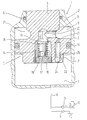
- the single figure shows an incompletely shown longitudinal section of the embodiment.
- a hand-operated hydraulic piston pump designated as a whole by 1, has a cylinder 2, in which a piston, designated as a whole by 3, is arranged so as to be longitudinally displaceable.
- the piston 3 is provided at one end with a piston rod 4 which is guided so as to be longitudinally displaceable in a guide 2 'which adjoins the end of the cylinder 2 which delimits the rod chamber 5.
- the sealing of the piston rod 4 in the guide 2 ' is indicated by an O-ring 6.
- the piston chamber 7, which is separated from the rod chamber 5 by the piston 3, is connected to a tank 10 via a connecting line 8 and a first check valve 9, and to a working cylinder 12 via a second check valve 11, which is, for example, the working cylinder of a lifting truck.
- the piston seal on the inside wall of the cylinder is an O-ring 13 formed, which lies in an annular groove of the piston 3.
- the piston has a central extension 3 ′ on the side delimiting the piston chamber 7, the outer diameter of which is smaller than the section adapted to the inner diameter of the cylinder 3, but larger than the diameter of the piston rod 4.
- This valve body 15 is arranged at one end of a guide sleeve 16 which is longitudinally displaceable on a guide pin 17 which projects from a perforated plate 18 which is screwed into the initial section of the blind hole 14.
- a helical compression spring 19 surrounding the guide sleeve 16 and the guide pin 17 is supported on the perforated plate 18 and loads the valve body 15 with the required force.
- a transverse bore 20 opens into the end section of the blind bore 14 located in the piston rod 4 and penetrates from an annular groove 21 provided at the transition from the piston rod 4 to the piston 3 into the piston rod 4 at right angles to its longitudinal axis.
- the preload of the helical compression spring 19 is selected such that the check valve opens and the hydraulic fluid flows into the piston chamber 7 even at a relatively low overpressure in the rod chamber 5 during the piston return stroke.
- a bore which penetrates from the end face of the piston 3 which delimits the piston chamber 7 22 is provided, which ends at a distance from the ring throat 21.
- the diameter of the bore 22 is, as the figure shows, much larger than that of the first throttle bore 23. Its axial length is also a multiple of the axial length of the first throttle bore 23.
- the beginning of the bore 22 is sealed by a closure body 24, at which in the exemplary embodiment is a ball pressed into the initial section of the bore 22.
- a second throttle bore 25 opens into the bore 22 at right angles to its longitudinal extension, which second bore opens into the lateral surface of the extension 3 '.
- the cross section of the two throttle bores 23 and 25 and their length are chosen so that during a working stroke of the piston 3 at a relatively high speed, the throttling effect is so strong that only a little hydraulic fluid can pass from the piston chamber 7 into the rod chamber 5, that on the other hand at relatively low speed of movement of the piston 3, there is largely pressure equalization between the piston chamber 7 and the rod chamber 5.
- the diameter of the bore 22 is substantially larger than that of the throttle bore 23 and 25, so that the section lying between the two throttle bores is not involved in the throttle effect.
Abstract
Description
Die Erfindung betrifft eine hydraulische Einkolbenpumpe, welche die Merkmale des Oberbegriffs des Anspruches 1 aufweist.The invention relates to a hydraulic single-piston pump, which has the features of the preamble of
Bei den bekannten Handpumpen diese Art (s.z.B. DE-A-2131802) erfolgt die selbsttätige Steuerung des Durchflusses von Hydraulikflüssigkeit durch den zweiten Kanal mittels eines in diesen Kanal eingebauten Ventiles, welches beim Überschreiten eines festgelegten Wertes des Druckes im Kolbenraum zu Beginn jedes Arbeitshubes öffnet, damit zwischen dem Kolbenraum um dem Stangenraum ein Druckausgleich erfolgt, wodurch die wirksame Pumpenfläche auf die Größe der Stangenfläche reduziert ist. Hierdurch wird die beim Arbeitshub auf den Kolben auszuübende Kraft selbsttätig reduziert, sobald der genannte Grenzwert überschritten wird. Man spricht daher von einer Zweistufenpumpe, die beispielsweise für Hubwagen Verwendung findet, bei denen man mit möglichst wenigen Pumpzyklen Lasten anheben will.In the known hand pumps of this type (see, for example, DE-A-2131802), the automatic control of the flow of hydraulic fluid through the second channel takes place by means of a valve built into this channel, which opens when a predetermined pressure in the piston chamber is exceeded at the beginning of each working stroke. so that a pressure equalization takes place between the piston space around the rod space, whereby the effective pump area is reduced to the size of the rod surface. As a result, the force to be exerted on the piston during the working stroke is automatically reduced as soon as the specified limit value is exceeded. One speaks therefore of a two-stage pump, which is used, for example, for pallet trucks, in which one wants to lift loads with as few pump cycles as possible.
Der Erfindung liegt die Aufgabe zugrunde, eine Einkolbenpumpe der eingangs genannten Art zu verbessern. Diese Aufgabe löst eine Pumpe mit den Merkmalen des Anspruches 1.The invention has for its object to improve a single-piston pump of the type mentioned. This object is achieved by a pump with the features of
Die Drosselbohrung des zweiten Kanals reduziert nicht nur die Kosten. Sie führt auch zu einer geringeren Störanfälligkeit selbst bei rauhen Betriebsbedingungen und erlaubt eine kleinere Bauhöhe. Vor allem führt die Drosselbohrung dazu, daß die beim Arbeitshub aufzubringende Kraft von der Betätigungsgeschwindigkeit, also der Pumpgeschwindigkeit, abhängt. Statt einer vom Benutzer nicht beeinflußbaren Umschaltung der effektiven Kolbenfläche beim Überschreiten oder Unterschreiten des festgelegten Grenzwertes des Druckes im Kolbenraum kann bei der erfindungsgemäßen Pumpe der Benutzer unabhängig vom Druck im Kolbenraum die auf den Kolben auszuübende Betätigungskraft innerhalb der durch den vollen Kolbenquerschnitt und den reduzierten Kolbenquerschnitt vorgegebenen Grenzen an seine Möglichkeiten anpassen. Wird beim Arbeitshub der Kolben so langsam bewegt, daß ein vollständiger Druckausgleich zwischen dem Kolbenraum und dem Stangenraum erreicht wird, dann ist unabhängig von dem im Kolbenraum herrschenden Druck die effektive Kolbenfläche gleich der Stangenquerschnittsfläche. Je schneller der Kolben beim Arbeitshub bewegt wird, desto größer bleibt die Druckdifferenz zwischen Kolbenraum und Stangenraum. Ist die erfindungsgemäße Pumpe beispielsweise einem Hubwagen zugeordnet, dann kann jede Last unabhängig von ihrer Größe durch eine höhere Pumpgeschwindigkeit, die allerdings auch einen höheren Kraftaufwand erfordert, mit weniger Pumpzyklen angehoben werden als bei einer geringeren Pumpgeschwindigkeit.The throttle bore of the second channel not only reduces costs. It also leads to less susceptibility to faults even under harsh operating conditions and allows a smaller overall height. Above all, the throttle bore means that the force to be applied during the working stroke depends on the actuation speed, that is to say the pump speed. Instead of switching the effective piston area, which cannot be influenced by the user, when the pressure in the piston chamber exceeds or falls below the specified limit value, the user can, in the pump according to the invention, independently of the pressure in the piston chamber, the actuating force to be exerted on the piston within the range defined by the full piston cross section and the reduced piston cross section Adapt borders to your possibilities. If the piston is moved so slowly during the working stroke that a complete pressure equalization between the piston chamber and the rod chamber is achieved, then regardless of the pressure prevailing in the piston chamber, the effective piston area is equal to the rod cross-sectional area. The faster the piston is moved during the working stroke, the greater the pressure difference between the piston chamber and the rod chamber. If the pump according to the invention is assigned, for example, to a lifting truck, then any load, regardless of its size, can be raised with fewer pumping cycles than with a lower pumping speed by means of a higher pumping speed, which, however, also requires more effort.
Ein weiterer Vorteil der erfindungsgemäßen Lösung besteht darin, daß beim Arbeitshub im Stangenraum kein Unterdruck entstehen kann, der bei nicht vollständig funktionsfähiger Stangenabdichtung zur Folge hat, daß Luft angesaugt wird.Another advantage of the solution according to the invention is that during the working stroke in the rod space no negative pressure can arise which, if the rod seal is not fully functional, results in air being sucked in.
Bei einer relativ geringen Länge des zweiten Kanales kann dieser auf seiner ganzen Länge als Drosselbohrung ausgebildet sein. In der Regel wird jedoch der zweite Kanal länger sein als die erforderliche Länge der Drosselstrecke. Man kann dann den zweiten Kanal mit Ausnahme des die Drosselbohrung bildenden Abschnittes mit einem größeren Durchmesser ausführen. Man kann aber auch, wie dies bei einer bevorzugten Ausführungsform der Fall ist, zwei im Abstand auf einander folgende Drosselbohrungen im Zuge des zweiten Kanals vorsehen. Diese beiden Drosselbohrungen sind dann durch einen im Durchmesser größeren Kanalabschnitt miteinander verbunden. Diese Ausführungsform hat fertigungstechnische und strömungstechnische Vorteile. Beispielweise ist es aus Gründen der Fertigungskosten vorteilhaft, wenn die eine der beiden Drosselbohrungen gleichachsig zu dem im Durchmesser größeren Abschnitt des zweiten Kanals angeordnet ist. Die zweite Drosselbohrung kann hierbei ebenfalls gleichachsig, aber auch im Winkel zu diesem Kanalabschnitt verlaufen.In the case of a relatively short length of the second channel, this can be designed as a throttle bore over its entire length. As a rule, however, the second channel will be longer than the required length of the throttle section. You can then run the second channel with the exception of the portion forming the throttle bore with a larger diameter. However, as is the case in a preferred embodiment, two throttle bores which follow one another at a distance can also be provided in the course of the second channel. These two throttle bores are then connected to one another by a channel section with a larger diameter. This embodiment has advantages in terms of production technology and flow technology. For example, for reasons of production costs, it is advantageous if one of the two throttle bores is arranged coaxially with the section of the second channel which is larger in diameter. The second throttle bore can also be coaxial, but can also run at an angle to this channel section.
Aus Fertigungsgründen dringt bei einer bevorzugten Ausführungsform der im Durchmesser größere Kanalabschnitt von der dem Kolbenraum zugekehrten Stirnfläche des Kolbens her in diesen ein. Die eine Drosselbohrung kann sich hierbei gleichachsig an das im Kolben liegende Ende anschließen. Die andere Drosselbohrung kann entweder in einem Verschlußkörper vorgesehen sein, der den Anfang dieses von der Kolbenstirnfläche her eindringenden Kanalabschnittes verschließt. Man kann aber die zweite Drosselbohrung auch zwischen den Verschlußkörper und der anderen Drosselstrecke in den Kanal einmünden lassen, beispielsweise von der Mantelfläche des Kolbens her.For manufacturing reasons, in a preferred embodiment, the channel section with a larger diameter penetrates from the end face of the piston facing the piston chamber. One throttle bore can connect coaxially to the end in the piston. The other throttle bore can either be provided in a closure body which closes the beginning of this channel section penetrating from the piston end face. But you can also let the second throttle bore open into the channel between the closure body and the other throttle section, for example from the outer surface of the piston.
Im folgenden ist die Erfindung anhand eines in der Zeichnung dargestellten Ausführungsbeispiels im einzelnen erläutert.The invention is explained in detail below using an exemplary embodiment shown in the drawing.
Die einzige Figur zeigt einen unvollständig dargestellten Längsschnitt des Ausführungsbeispiels.The single figure shows an incompletely shown longitudinal section of the embodiment.
Eine als Ganzes mit 1 bezeichnete, von Hand zu betätigende hydraulische Kolbenpumpe weist einen Zylinder 2 auf, in dem längsverschiebbar ein als Ganzes als 3 bezeichneter Kolben angeordnet ist. Der Kolben 3 ist am einen Ende mit einer Kolbenstange 4 vorgesehen, die in einer Führung 2' längsverschiebbar geführt ist, welche sich an das den Stangenraum 5 begrenzende Ende des Zylinders 2 anschließt. Die Abdichtung der Kolbenstange 4 in der Führung 2' ist durch einen O-Ring 6 angedeutet. Der vom Stangenraum 5 durch den Kolben 3 getrennte Kolbenraum 7 ist über eine Verbindungsleitung 8 und ein erstes Rückschlagventil 9 mit einem Tank 10 sowie über ein zweites Rückschlagventil 11 mit einem Arbeitszylinder 12 verbunden, bei dem es sich beispielsweise um den Arbeitszylinder eines Hubwagens handelt. Die an der Zylinderinnenwand anliegende Kolbendichtung ist als O-Ring 13 ausgebildet, der in einer Ringnut des Kolbens 3 liegt.A hand-operated hydraulic piston pump, designated as a whole by 1, has a
Der Kolben weist auf der den Kolbenraum 7 begrenzenden Seite einen zentralen Fortsatz 3' auf, dessen Außendurchmesser kleiner als der an den Innendurchmesser des Zylinders 3 angepaßte Abschnitt, jedoch größer als der Durchmesser der Kolbenstange 4 ist.The piston has a
Eine von der den Kolbenraum 7 begrenzenden Stirnfläche des 1 bens 3 her zentral in diesen eindringende Sacklochbohrung bildet im Abstand von dem in die Kolbenstange 4 eindringenden Endabschnitt eine Ringschulter, die als Sitz für einen federbelasteten Ventilkörper 15 eines Rückschlagventiles bildet. Dieser Ventilkörper 15 ist am einen Ende einer Führungshülse 16 angeordnet, welche längsverschiebbar auf einem Führungszapfen 17 sitzt, der von einer Lochplatte 18 absteht, die in den Anfangsabschnitt der Sacklochbohrung 14 eingeschraubt ist. Eine die Führungshülse 16 und den Führungszapfen 17 umgebende Schraubendruckfeder 19 stützt sich an der Lochplatte 18 ab und belastet den Ventilkörper 15 mit der erforderlichen Kraft. In den in der Kolbenstange 4 liegenden Endabschnitt der Sacklochbohrung 14 mündet eine Querbohrung 20, die von einer am Übergang von der Kolbenstange 4 zum Kolben 3 vorgesehenen Ringkehle 21 her in die Kolbenstange 4 rechtwinklig zu deren Längachse eindringt. Die Vorspannung der Schraubendruckfeder 19 ist so gewählt, daß schon bei einem relativ geringen Überdruck im Stangenraum 5 beim Kolbenrückhub das Rückschlagventil öffnet und die Hydraulikflüssigkeit in den Kolbenraum 7 strömen läßt.One of the end face of the
Parallel zur Längsachse des Kolbens 3 und der Kolbenstange 4, jedoch in einem Abstand von dieser Längsachse, die etwas größer ist als der Halbmesser der Ringkehle 21 am Grund der Kehle ist eine von der den Kolbenraum 7 begrenzenden Stirnfläche des Kolbens 3 her in diesen eindringende Bohrung 22 vorgesehen, die im Abstand von der Ringkehle 21 endet. An dieses Ende schließt sich gleichachsig eine erste Drosselbohrung 23 an, welche in die Ringkehle 21 mündet. Der Durchmesser der Bohrung 22 ist, wie die Figur zeigt, wesentlich größer als derjenige der ersten Drosselbohrung 23. Auch ihre axiale Länge beträgt ein Mehrfaches der axialen Länge der ersten Drosselbohrung 23. Der Anfang der Bohrung 22 ist mittels eines Verschlußkörpers 24 dicht verschlossen, bei dem es sich im Ausführungsbeispiel um eine in den Anfangsabschnitt der Bohrung 22 eingepreßte Kugel handelt. Zwischen dem Verschlußkörper 24 und der ersten Drosselbohrung 23 mündet in die Bohrung 22 rechtwinklig zu deren Längserstreckung eine zweite Drosselbohrung 25, die andererseits in der Mantelfläche des Fortsatzes 3' mündet.Parallel to the longitudinal axis of the
Der Querschnitt der beiden Drosselbohrungen 23 und 25 sowie ihre Länge sind so gewählt, daß bei einem Arbeitshub des Kolbens 3 mit relativ großer Geschwindigkeit die Drosselwirkung so stark ist, daß nur wenig Hydraulikflüssigkeit vom Kolbenraum 7 in den Stangenraum 5 übertreten kann, daß andererseits bei einer relativ geringen Bewegungsgeschwindigkeit des Kolbens 3 ein weitgehender Druckausgleich zwischen dem Kolbenraum 7 und dem Stangenraum 5 erfolgt. Der Durchmesser der Bohrung 22 ist wesentlich größer als derjenige der Drosselbohrung 23 und 25, so daß der zwischen den beiden Drosselbohrungen liegende Abschnitt an der Drosselwirkung nicht beteiligt ist.The cross section of the two throttle bores 23 and 25 and their length are chosen so that during a working stroke of the
Claims (7)
Applications Claiming Priority (2)
| Application Number | Priority Date | Filing Date | Title |
|---|---|---|---|
| DE3710919A DE3710919C1 (en) | 1987-04-01 | 1987-04-01 | Hydraulic single piston pump for manual operation |
| DE3710919 | 1987-04-01 |
Publications (2)
| Publication Number | Publication Date |
|---|---|
| EP0308468A1 EP0308468A1 (en) | 1989-03-29 |
| EP0308468B1 true EP0308468B1 (en) | 1990-08-22 |
Family
ID=6324601
Family Applications (1)
| Application Number | Title | Priority Date | Filing Date |
|---|---|---|---|
| EP88903168A Expired - Lifetime EP0308468B1 (en) | 1987-04-01 | 1988-03-31 | Hydraulic manually-operated single-piston pump |
Country Status (5)
| Country | Link |
|---|---|
| US (1) | US4923373A (en) |
| EP (1) | EP0308468B1 (en) |
| JP (1) | JPH01502840A (en) |
| DE (1) | DE3710919C1 (en) |
| WO (1) | WO1988007495A1 (en) |
Families Citing this family (9)
| Publication number | Priority date | Publication date | Assignee | Title |
|---|---|---|---|---|
| TW232759B (en) * | 1992-03-16 | 1994-10-21 | Wagner Spray Tech Corp | |
| US5318139A (en) * | 1993-04-29 | 1994-06-07 | Evans Robert W | Reduced waiting time hydraulic drilling jar |
| US5624001A (en) | 1995-06-07 | 1997-04-29 | Dailey Petroleum Services Corp | Mechanical-hydraulic double-acting drilling jar |
| DE19848035A1 (en) * | 1998-10-17 | 2000-04-20 | Bosch Gmbh Robert | Radial piston pump for high fuel pressure in IC engines with common-rail injection system has suction valve closure spring supported on pump piston and contained in long piston bore |
| US6290004B1 (en) | 1999-09-02 | 2001-09-18 | Robert W. Evans | Hydraulic jar |
| US6481495B1 (en) | 2000-09-25 | 2002-11-19 | Robert W. Evans | Downhole tool with electrical conductor |
| DE102004028999A1 (en) * | 2004-06-16 | 2006-01-05 | Robert Bosch Gmbh | High-pressure pump for a fuel injection device of an internal combustion engine |
| US9630469B2 (en) * | 2010-10-18 | 2017-04-25 | Firestone Industrial Products Company, Llc | Gas spring and gas damper assembly and method |
| DE102018213997A1 (en) * | 2018-08-20 | 2020-02-20 | Robert Bosch Gmbh | pump assembly |
Family Cites Families (6)
| Publication number | Priority date | Publication date | Assignee | Title |
|---|---|---|---|---|
| US3112705A (en) * | 1961-10-05 | 1963-12-03 | Jane Wallen | Two-speed hydraulic pumps |
| DE2131802C3 (en) * | 1971-06-26 | 1974-05-16 | Josef Bautz Gmbh, 7968 Saulgau | Device for draining the lifting fluid from the pressure chamber of a push piston pump |
| DE2551336B2 (en) * | 1975-11-15 | 1979-08-30 | Jungheinrich Unternehmensverwaltung Kg, 2000 Hamburg | Hydraulic lifting device with a load stroke cylinder piston unit |
| US4357798A (en) * | 1980-03-13 | 1982-11-09 | Michael Hung | Rapid actuating device of hydraulic actuator |
| US4520908A (en) * | 1983-11-10 | 1985-06-04 | General Motors Corporation | Pressure balanced valve for adjustable hydraulic damper |
| FR2560938A1 (en) * | 1984-03-12 | 1985-09-13 | Antkowiak Stephane | Hydraulic jack operated by a hand pump which may or may not be incorporated to the jack. |
-
1987
- 1987-04-01 DE DE3710919A patent/DE3710919C1/en not_active Expired
-
1988
- 1988-03-31 JP JP63503012A patent/JPH01502840A/en active Pending
- 1988-03-31 WO PCT/DE1988/000211 patent/WO1988007495A1/en active IP Right Grant
- 1988-03-31 US US07/276,321 patent/US4923373A/en not_active Expired - Fee Related
- 1988-03-31 EP EP88903168A patent/EP0308468B1/en not_active Expired - Lifetime
Also Published As
| Publication number | Publication date |
|---|---|
| EP0308468A1 (en) | 1989-03-29 |
| DE3710919C1 (en) | 1988-06-30 |
| JPH01502840A (en) | 1989-09-28 |
| WO1988007495A1 (en) | 1988-10-06 |
| US4923373A (en) | 1990-05-08 |
Similar Documents
| Publication | Publication Date | Title |
|---|---|---|
| EP0565982A1 (en) | Valve arrangement | |
| DE2109378C3 (en) | Check valve with additional actuation | |
| EP0308468B1 (en) | Hydraulic manually-operated single-piston pump | |
| DE2945911C2 (en) | ||
| DE19716042C1 (en) | Hydraulic valve control device for internal combustion engine | |
| EP0863342B1 (en) | Pressure control valve | |
| DE4234626C2 (en) | Pressure controlled valve | |
| DE970609C (en) | Valve arrangement for hydraulic systems | |
| DE2322354A1 (en) | WORK CYLINDERS, IN PARTICULAR HYDRAULIC CYLINDERS, WITH A DAMPING DEVICE FOR THE END OF THE WORKING STROKE OF THE PISTON | |
| EP0051728A1 (en) | Hydraulic motor control system | |
| DE2716694C2 (en) | ||
| DE2929232C2 (en) | ||
| DE874277C (en) | Hydraulic lifting device for stacking devices | |
| DE3135098A1 (en) | Valve construction comprising a pump control or regulating valve and a relief arrangement | |
| DE3737579A1 (en) | Trailer brake valve | |
| DE3006530A1 (en) | Hydraulic locking ball valve - has valve controlled suction device reducing pressure in actuation chamber to open valve | |
| DE2932523C2 (en) | Hydraulically releasable seat valve | |
| DE636841C (en) | Fluid brake, especially for lift trucks | |
| EP0921321A1 (en) | Seat-valve-type hydraulic stop valve | |
| DE3048746A1 (en) | Hydraulic system with double-acting ram - has each control valve connected to relief valve of other one | |
| DE1051591B (en) | Valve for hydraulic systems | |
| DE19822872A1 (en) | Dosing pump for liquid fuel, especially fuel powered heater of motor vehicle | |
| DE4001197C2 (en) | Seat valve | |
| DE2214245A1 (en) | TWIN NON-RETURN VALVE | |
| DE4234742A1 (en) | Valve unit for position control of harvester - has pressure-limiting valve and non-return valve, spring for latter being weaker than for former |
Legal Events
| Date | Code | Title | Description |
|---|---|---|---|
| PUAI | Public reference made under article 153(3) epc to a published international application that has entered the european phase |
Free format text: ORIGINAL CODE: 0009012 |
|
| 17P | Request for examination filed |
Effective date: 19881125 |
|
| AK | Designated contracting states |
Kind code of ref document: A1 Designated state(s): CH FR LI SE |
|
| 17Q | First examination report despatched |
Effective date: 19900124 |
|
| GRAA | (expected) grant |
Free format text: ORIGINAL CODE: 0009210 |
|
| AK | Designated contracting states |
Kind code of ref document: B1 Designated state(s): CH FR LI SE |
|
| ET | Fr: translation filed | ||
| PLBE | No opposition filed within time limit |
Free format text: ORIGINAL CODE: 0009261 |
|
| STAA | Information on the status of an ep patent application or granted ep patent |
Free format text: STATUS: NO OPPOSITION FILED WITHIN TIME LIMIT |
|
| 26N | No opposition filed | ||
| EAL | Se: european patent in force in sweden |
Ref document number: 88903168.8 |
|
| PGFP | Annual fee paid to national office [announced via postgrant information from national office to epo] |
Ref country code: SE Payment date: 19950216 Year of fee payment: 8 Ref country code: CH Payment date: 19950216 Year of fee payment: 8 |
|
| PGFP | Annual fee paid to national office [announced via postgrant information from national office to epo] |
Ref country code: FR Payment date: 19950228 Year of fee payment: 8 |
|
| PG25 | Lapsed in a contracting state [announced via postgrant information from national office to epo] |
Ref country code: LI Effective date: 19960331 Ref country code: CH Effective date: 19960331 |
|
| PG25 | Lapsed in a contracting state [announced via postgrant information from national office to epo] |
Ref country code: SE Effective date: 19960401 |
|
| REG | Reference to a national code |
Ref country code: CH Ref legal event code: PL |
|
| PG25 | Lapsed in a contracting state [announced via postgrant information from national office to epo] |
Ref country code: FR Effective date: 19961129 |
|
| EUG | Se: european patent has lapsed |
Ref document number: 88903168.8 |
|
| REG | Reference to a national code |
Ref country code: FR Ref legal event code: ST |