EP0306754B1 - Einrichtung zur Herstellung einer Abzweigung von einer einzelnen Ader eines Mehrleiterkabels - Google Patents
Einrichtung zur Herstellung einer Abzweigung von einer einzelnen Ader eines Mehrleiterkabels Download PDFInfo
- Publication number
- EP0306754B1 EP0306754B1 EP88113552A EP88113552A EP0306754B1 EP 0306754 B1 EP0306754 B1 EP 0306754B1 EP 88113552 A EP88113552 A EP 88113552A EP 88113552 A EP88113552 A EP 88113552A EP 0306754 B1 EP0306754 B1 EP 0306754B1
- Authority
- EP
- European Patent Office
- Prior art keywords
- clamping
- clamping element
- cupped
- gripping points
- recess
- Prior art date
- Legal status (The legal status is an assumption and is not a legal conclusion. Google has not performed a legal analysis and makes no representation as to the accuracy of the status listed.)
- Expired - Lifetime
Links
- 239000004020 conductor Substances 0.000 claims description 11
- 239000012774 insulation material Substances 0.000 claims description 3
- 238000004519 manufacturing process Methods 0.000 claims description 3
- 239000011810 insulating material Substances 0.000 abstract description 3
- 230000000149 penetrating effect Effects 0.000 abstract 1
- 125000006850 spacer group Chemical group 0.000 description 2
- 239000011248 coating agent Substances 0.000 description 1
- 238000000576 coating method Methods 0.000 description 1
- 230000001419 dependent effect Effects 0.000 description 1
- 238000005553 drilling Methods 0.000 description 1
- 238000009434 installation Methods 0.000 description 1
- 210000003462 vein Anatomy 0.000 description 1
Images

Classifications
-
- H—ELECTRICITY
- H01—ELECTRIC ELEMENTS
- H01R—ELECTRICALLY-CONDUCTIVE CONNECTIONS; STRUCTURAL ASSOCIATIONS OF A PLURALITY OF MUTUALLY-INSULATED ELECTRICAL CONNECTING ELEMENTS; COUPLING DEVICES; CURRENT COLLECTORS
- H01R4/00—Electrically-conductive connections between two or more conductive members in direct contact, i.e. touching one another; Means for effecting or maintaining such contact; Electrically-conductive connections having two or more spaced connecting locations for conductors and using contact members penetrating insulation
- H01R4/24—Connections using contact members penetrating or cutting insulation or cable strands
- H01R4/2404—Connections using contact members penetrating or cutting insulation or cable strands the contact members having teeth, prongs, pins or needles penetrating the insulation
- H01R4/2408—Connections using contact members penetrating or cutting insulation or cable strands the contact members having teeth, prongs, pins or needles penetrating the insulation actuated by clamping screws
-
- H—ELECTRICITY
- H01—ELECTRIC ELEMENTS
- H01R—ELECTRICALLY-CONDUCTIVE CONNECTIONS; STRUCTURAL ASSOCIATIONS OF A PLURALITY OF MUTUALLY-INSULATED ELECTRICAL CONNECTING ELEMENTS; COUPLING DEVICES; CURRENT COLLECTORS
- H01R4/00—Electrically-conductive connections between two or more conductive members in direct contact, i.e. touching one another; Means for effecting or maintaining such contact; Electrically-conductive connections having two or more spaced connecting locations for conductors and using contact members penetrating insulation
- H01R4/28—Clamped connections, spring connections
- H01R4/38—Clamped connections, spring connections utilising a clamping member acted on by screw or nut
- H01R4/44—Clamping areas on both sides of screw
Definitions
- the present invention relates to a device for producing a branch from a single insulated wire of a multi-conductor cable, a first and a second clamping element being able to be brought into clamping contact with one another by means of a screw arrangement.
- branch terminal which consists of detachably connectable segments, spacers being provided between the individual segments.
- a device for producing a branch from a single insulated wire of a multi-conductor cable according to the preamble of claim 1 is known from document DE-A-2 903 960.
- the present invention has for its object to provide a device for branching a single insulated wire of a multi-conductor cable, which can be assembled in a very simple manner with a minimum number of individual parts without much time.
- the features according to the invention result in a simple clamping contact of the main wire by means of a screw with simple assembly.
- the distance between the tilting support and the recesses for the main wire ensures high clamping forces.
- a device shown in FIGS. 1 and 2 for branching a single insulated wire of a multi-conductor cable has a first 1 and a second 2 clamping element. These two clamping elements can be pressed against one another by means of a screw arrangement 3, so that a clamping contact arises between the individual elements 1 and 2.
- the first clamping element 1 has a projection 5 through which a bore 4 runs. This hole is intended to accommodate a branch conductor.
- a recess 7 is provided in the first clamping element 1. This recess is designed to span the main vein.
- the second clamping element 2 each has a recess 15 and 9, the part-circular recess 15 forming the support part 8 for the clamping element 1.
- the radius of the recess 15 corresponds approximately to the radius of the projection 5, so that when the clamping contact is produced, the projection 5 is spanned by the recess 15 along a wide area of its circumference.
- the projection 5 can be rotated about the drilling axis 6 in the recess 15, the recess 15 forming a tilting support 16. In the case of a clamp contact to be produced, this arrangement also guarantees the necessary anti-rotation protection.
- the clamping elements are provided with an insulating surface coating.
- the recessed clamping screws 3a make the proposed clamp very space-saving.
- the assembly is also correspondingly simple:
- a prepared branch conductor is guided through the bore 4 and clamped by means of a screw 13.
- the clamping element with its recesses 7 and 9 is then pushed onto the main wire.
- the screw 3a is tightened so that the clamping elements 1 and 2 are brought into clamping contact.
- the annular cutting edges 11 penetrate into the insulating material of the main wire and displace it into the cavities 12. As soon as the annular cutting edges 11 have penetrated the insulating material, the clamping contact is produced.
- the projection 5 of the clamping element 1 is nose-shaped.
- the support part 8 of the clamping element 2 has a flat support surface 10, whereby the rounded nose creates a linear support of the clamping element 1 on the clamping part 2, about which the clamping element 2 can be pivoted about the tilting support 16 when tightened by means of the screw arrangement 3.
- the clamping element 1 has an eye 14 for the screw 13 for clamping the branch conductor in the bore 4.
- a contact surface 10 is arranged on each side of the eye 14.
- the arrangement of the projections 5 on both sides of the eye 14 prevents the two clamping elements 1, 2 from rotating relative to one another when the screw 3a is tightened.
- the recesses 9 and 7 with the annular cutting edges 11 correspond to the embodiment variant shown in FIGS. 1 and 2, wherein the cavities 12 between the annular cutting edges 11 can also be semicircular in cross section in order to reduce notch stresses, as shown in FIG. 2a.
Landscapes
- Suspension Of Electric Lines Or Cables (AREA)
- Testing Of Short-Circuits, Discontinuities, Leakage, Or Incorrect Line Connections (AREA)
- Connections By Means Of Piercing Elements, Nuts, Or Screws (AREA)
- Multi-Conductor Connections (AREA)
- Cable Accessories (AREA)
- Communication Cables (AREA)
Description
- Die vorliegende Erfindung betrifft eine Einrichtung zur Herstellung einer Abzweigung von einer einzelnen isolierten Ader eines Mehrleiterkabels, wobei je ein erstes und ein zweites Klemmelement mittels einer Schraubenanordnung gegeneinander in Klemmkontakt bringbar sind.
- Es sind verschiedene Arten von Einrichtungen zur Abzweigung einer Ader eines Mehrleiterkabels bekannt, wobei die meisten Ausführungen in der Art eines Klemmringes Verwendung finden.
- Aus der DE-OS 2143219 ist eine Abzweigklemme bekannt, welche aus lösbar miteinander verbindbaren Segmenten besteht, wobei zwischen den einzelnen Segmenten Distanzstücke vorgesehen sind.
- Eine solche bekannte Ausführung bedingt eine Vielzahl von Einzelteilen wie Segmente, Abstandhalter etc., was die Montage erschwert und auch Ursache von Fehlerquellen sein kann.
- Eine Einrichtung zur Herstellung einer Abzweigung von einer einzelnen isolierten Ader eines Mehrleiterkabels gemäß dem Oberbegriff des Anspruchs 1 ist vom Dokument DE-A-2 903 960 bekannt.
- Der vorliegenden Erfindung liegt die Aufgabe zu Grunde, eine Einrichtung zur Abzweigung einer einzelnen isolierten Ader eines Mehrleiterkabels zu schaffen, die in einfachster Weise mit einer Mindestzahl von Einzelteilen ohne grossen Zeitaufwand montierbar ist.
- Diese Aufgabe wird durch die kennzeichnenden Merkmale von Anspruch 1 gelöst.
- Durch die erfindungsgemässen Merkmale wird ein einfacher Klemmkontakt der Hauptader mittels einer Schraube bei einfacher Montage erreicht. Der Abstand zwischen der Kippauflage und den Ausnehmungen für die Hauptader gewährleistet hohe Klemmkräfte.
- Besonders vorteilhafte Ausgestaltungen gehen aus den abhängigen Ansprüchen hervor.
- Anhand der beiliegenden Figuren werden Ausführungsbeispiele der Einrichtung näher beschrieben.
- Es zeigen:
- Fig. 1
- einen Schnitt durch eine Einrichtung zur Herstellung einer Abzweigung von einer einzelnen isolierten Ader eines Mehrleiterkabels
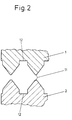
- Fig. 2
- einen Schnitt entlang der Linie B-B aus der Fig. 1 in vergrösserter Darstellung
- Fig. 2a
- eine Ausführungsvariante von der in Fig. 2 gezeigten Schnittpartie
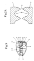
- Fig. 3
- eine Ausführungsvariante von der in Fig. 1 gezeigten Einrichtung gemäß der Erfindung.
- Eine in den Fig. 1 und 2 gezeigte Einrichtung zur Abzweigung einer einzelnen isolierten Ader eines Mehrleiterkabels weist ein erstes 1 und ein zweites 2 Klemmelement auf. Diese zwei Klemmelemente sind mittels einer Schraubenanordnung 3 gegeneinander drückbar, so dass zwischen den einzelnen Elementen 1 und 2 ein Klemmkontakt entsteht. Das erste Klemmelement 1 weist einen Vorsprung 5 auf, durch den eine Bohrung 4 verläuft. Diese Bohrung ist zur Aufnahme eines Abzweigleiters bestimmt. Von der Bohrung 4 beabstandet ist eine Ausnehmung 7 im ersten Klemmelement 1 vorgesehen. Diese Ausnehmung ist dazu bestimmt, die Hauptader zu umspannen.
- Das zweite Klemmelement 2 weist je eine Ausnehmung 15 und 9 auf, wobei die teilkreisförmige Ausnehmung 15 den Auflageteil 8 für das Klemmelement 1 bildet. Der Radius der Ausnehmung 15 entspricht in etwa dem Radius des Vorsprunges 5, so dass bei hergestelltem Klemmkontakt der Vorsprung 5 von der Ausnehmung 15 entlang eines weiten Bereiches seines Umfanges umspannt wird. Der Vosprung 5 ist um die Bohrachse 6 in der Ausnehmung 15 drehbar, wobei die Ausnehmung 15 eine Kippauflage 16 bildet. Diese Anordnung bietet bei herzustellendem Klemmkontakt auch Gewähr für die notwendige Verdrehsicherung.
- Die Ausnehmungen 9 und 7, die dem Umfang der Hauptader angepasst sind, weisen Ringschneiden 11 auf. Diese Ringschneiden sind dazu bestimmt, das Isolationsmaterial zu durchdringen und so nach erfolgter Montage den Stromfluss herzustellen. Zwischen den einzelnen Ringschneiden sind Hohlräume 12 vorgesehen, die das durch die Ringschneiden 11 verdrängte Isolationsmaterial aufnehmen können. Dadurch wird ein einwandfreier Kontakt gewährleistet.
- Die Klemmelemente sind wie üblich mit einer isolierenden Oberflächenbeschichtung versehen.
- Durch die versenkten Klemmschrauben 3a ist die vorgeschlagene Klemme sehr platzsparend. Auch die Montage gestaltet sich entsprechend einfach:
- Zunächst wird durch die Bohrung 4 ein vorbereiteter Abzweigleiter geführt und mittels einer Schraube 13 festgeklemmt. Das Klemmelement mit seinen Ausnehmungen 7 und 9 wird sodann auf die Hauptader geschoben. Die Schraube 3a wird angezogen, so dass die Klemmelemente 1 und 2 in Klemmkontakt gebracht werden. Während der Herstellung dieses Klemmkontaktes durch Anziehen der Schraubenanordnung 3 dringen die Ringschneiden 11 in das Isoliermaterial der Hauptader ein und verdrängen dieses in die Hohlräume 12. Sobald die Ringschneiden 11 das Isoliermaterial durchdrungen haben, ist der Klemmkontakt hergestellt.
- Die Fig. 3 zeigt eine Ausführungsvariante der Einrichtung gemäß der Erfindung. Hierbei ist der Vorsprung 5 des Klemmelementes 1 nasenförmig ausgebildet.
- Das Auflageteil 8 des Klemmelementes 2 weist eine ebene Auflagefläche 10 auf, wobei durch die abgerundete Nase eine linienförmige Auflage des Klemmelementes 1 auf dem Klemmteil 2 entsteht, um welche beim Zusammenspannen mittels der Schraubenanordnung 3 das Klemmelement 2 um die Kippauflage 16 schwenkbar ist.
- Für die Schraube 13 zur Klemmung des Abzweigleiters in der Bohrung 4 weist das Klemmelement 1 ein Auge 14 auf. Beidseits des Auges 14 ist je eine Auflagefläche 10 angeordnet.
- Durch die Anordnung der Vorsprünge 5 beidseits des Auges 14 wird ein gegenseitiges Verdrehen der beiden Klemmelemente 1, 2 beim Anziehen der Schraube 3a verhindert.
- Die Ausnehmungen 9 und 7 mit den Ringschneiden 11 entsprechen der in der Fig. 1 und 2 gezeigten Ausführungsvariante, wobei die Hohlräume 12 zwischen den Ringschneiden 11 zur Verringerung von Kerbspannungen im Querschnitt auch halbkreisförmig ausgebildet sein können, wie dies in Fig. 2a dargestellt ist.
Claims (6)
- Einrichtung zur Herstellung einer Abzweigung von einer einzelnen isolierten Ader eines Mehrleiterkabels mit einem ersten Klemmelement (1), welches mindestens einen Vorsprung (5) und eine von diesem beabstandete Ausnehmung (7), die zur Aufnahme einer Haupt-Ader vorgesehen ist, aufweist, und einem zweiten Klemmelement (2), welches einen mit dem Vorsprung (5) als Kippauflage (16) zusammenwirkenden Auflageteil (8) und eine zweite Ausnehmung (9) aufweist, wobei die beiden Ausnehmungen (7,9) beim Verspannen der beiden Klemmelemente (1,2) mittels einer Schraubenanordnung (3) durch einen hergestellten Klemmkontakt die Hauptader mindestens teilweise umschliessen, und dass im Auflageteile (8) eine Bohrung (4) zur Aufnahme eines Abzweigleiters angeordnet ist, dadurch gekennzeichnet, dass das Auflageteil (8) eine ebene Auflagefläche (10) aufweist und dass zwei nasenförmige Vorsprünge (5) des ersten Klemmelementes (1) beidseits eines Auges (14) für eine Klemmschraube (13) des zweiten Klemmelementes (2) auf den Auflageflächen (10) aufliegend angeordnet sind und eine Verdrehsicherung bilden.
- Einrichtung nach Anspruch 1, dadurch gekennzeichnet, dass die Ausnehmungen (7,9) Ringschneiden (11) aufweisen.
- Einrichtung nach Anspruch 1, dadurch gekennzeichnet, dass die Schraubenanordnung (3) im Klemmelement (1) versenkt angeordnet ist.
- Einrichtung nach Anspruch 2, dadurch gekennzeichnet, dass dass zwischen den Ringschneiden (11) Hohlräume (12) vorgesehen sind, die bei hergestelltem Klemmkontakt durch die Ringschneiden (11) verdrängtes Isolationsmaterial aufnehmen.
- Einrichtung nach Anspruch 4, dadurch gekennzeichnet, dass die Hohlräume (12) zwischen den Ringschneiden (11) zur Verringerung von Kerbspannungen im Querschnitt halbkreisförmig ausgebildet sind.
- Einrichtung nach einem der Ansprüche 1 bis 5, dadurch gekennzeichnet dass die Klemmelemente (1,2) isolierte Oberflächen aufweisen.
Priority Applications (1)
| Application Number | Priority Date | Filing Date | Title |
|---|---|---|---|
| AT88113552T ATE83338T1 (de) | 1987-09-07 | 1988-08-20 | Einrichtung zur herstellung einer abzweigung von einer einzelnen ader eines mehrleiterkabels. |
Applications Claiming Priority (2)
| Application Number | Priority Date | Filing Date | Title |
|---|---|---|---|
| CH3440/87 | 1987-09-07 | ||
| CH3440/87A CH673910A5 (de) | 1987-09-07 | 1987-09-07 |
Publications (3)
| Publication Number | Publication Date |
|---|---|
| EP0306754A2 EP0306754A2 (de) | 1989-03-15 |
| EP0306754A3 EP0306754A3 (en) | 1990-06-13 |
| EP0306754B1 true EP0306754B1 (de) | 1992-12-09 |
Family
ID=4256002
Family Applications (1)
| Application Number | Title | Priority Date | Filing Date |
|---|---|---|---|
| EP88113552A Expired - Lifetime EP0306754B1 (de) | 1987-09-07 | 1988-08-20 | Einrichtung zur Herstellung einer Abzweigung von einer einzelnen Ader eines Mehrleiterkabels |
Country Status (5)
| Country | Link |
|---|---|
| EP (1) | EP0306754B1 (de) |
| AT (1) | ATE83338T1 (de) |
| CH (1) | CH673910A5 (de) |
| DE (1) | DE3876548D1 (de) |
| DK (1) | DK167787B1 (de) |
Families Citing this family (1)
| Publication number | Priority date | Publication date | Assignee | Title |
|---|---|---|---|---|
| CN102646954A (zh) * | 2012-05-17 | 2012-08-22 | 天津玖辰机械设备制造有限公司 | 一种用于低压电力电缆的机械式分支连接器 |
Family Cites Families (4)
| Publication number | Priority date | Publication date | Assignee | Title |
|---|---|---|---|---|
| DE1117685C2 (de) * | 1958-09-08 | 1962-06-07 | Alois Schiffmann Dipl Kfm | Zweibacken-Starkstromklemme |
| DE1198435B (de) * | 1961-04-17 | 1965-08-12 | Alois Schiffmann Dipl Kfm | Verbindungs- und Abzweigklemme fuer isolierte Leitungen |
| FR2294556A1 (fr) * | 1974-12-12 | 1976-07-09 | Verlant Et Beaurain | Connecteur de derivation, notamment pour lignes sous tension |
| DE2903960C3 (de) * | 1979-02-02 | 1984-01-19 | Karl Pfisterer Elektrotechnische Spezialartikel Gmbh & Co Kg, 7000 Stuttgart | Vollisolierte Abzweigklemme |
-
1987
- 1987-09-07 CH CH3440/87A patent/CH673910A5/de not_active IP Right Cessation
-
1988
- 1988-08-20 EP EP88113552A patent/EP0306754B1/de not_active Expired - Lifetime
- 1988-08-20 DE DE8888113552T patent/DE3876548D1/de not_active Expired - Fee Related
- 1988-08-20 AT AT88113552T patent/ATE83338T1/de not_active IP Right Cessation
- 1988-09-06 DK DK495088A patent/DK167787B1/da not_active Application Discontinuation
Also Published As
| Publication number | Publication date |
|---|---|
| EP0306754A2 (de) | 1989-03-15 |
| DK167787B1 (da) | 1993-12-13 |
| DK495088D0 (da) | 1988-09-06 |
| DK495088A (da) | 1989-03-08 |
| CH673910A5 (de) | 1990-04-12 |
| ATE83338T1 (de) | 1992-12-15 |
| EP0306754A3 (en) | 1990-06-13 |
| DE3876548D1 (de) | 1993-01-21 |
Similar Documents
| Publication | Publication Date | Title |
|---|---|---|
| DE3225175C2 (de) | Abschirmanschluß | |
| EP1423890B1 (de) | Kabelverbinder | |
| DE2735838C2 (de) | Elektrische Anschlußklemme und elektrisches Kabelverbindungsglied | |
| DE1918591C3 (de) | Elektrische Anschlußklemme | |
| DE19604564C1 (de) | Anschlußdose für ein Datennetz | |
| DE2305403C3 (de) | Lötfreie Anschlußstelle | |
| EP0083738A2 (de) | Mit Schneidklemmen versehenes elektrisches Kabelanschlusselement | |
| DE29807839U1 (de) | Batterie-Verbindungselement | |
| EP0306754B1 (de) | Einrichtung zur Herstellung einer Abzweigung von einer einzelnen Ader eines Mehrleiterkabels | |
| EP1086513B1 (de) | Anschlussklemme | |
| DE2653357A1 (de) | Klemmelement zum abisolierfreien anschluss elektrischer leiter | |
| DE8804388U1 (de) | Schneidklemme, zum Anschließen eines elektrischen Schaltdrahtes | |
| EP0212643B1 (de) | Seilabspannklemme | |
| DE69804524T2 (de) | Isolations-Perforierverbinder | |
| DE2102329A1 (de) | Leitungsverbinder | |
| DE3623399C1 (en) | Totally insulated anchor clamp (tension clamp, dead-end clamp) | |
| DE2352430C3 (de) | Elektrische Anschluß- oder/und Verbindungsklemme für insbesondere rohrförmige Leiter | |
| EP0993689B1 (de) | Anschlussvorrichtung für isolierte elektrische leiter ohne abisolierung | |
| DE3420941C2 (de) | Vorrichtung zum Verbinden elektrischer Leiter mit verstärkten Enden | |
| DE2932966C2 (de) | ||
| DE3216096A1 (de) | Reihenklemme fuer fernmeldekabeladern | |
| AT394647B (de) | Vollisolierte abzweigklemme fuer isolierte freileitungsleiter | |
| DE3507067C2 (de) | Abspannklemme | |
| DE2104196C3 (de) | Isolierender Trägerblock zur Aufnahme von lösbaren Verbindungselementen für eine elektrische Kontaktierung von Haupt- und Abzweigleitungen | |
| DE3436256C2 (de) |
Legal Events
| Date | Code | Title | Description |
|---|---|---|---|
| PUAI | Public reference made under article 153(3) epc to a published international application that has entered the european phase |
Free format text: ORIGINAL CODE: 0009012 |
|
| 17P | Request for examination filed |
Effective date: 19880820 |
|
| AK | Designated contracting states |
Kind code of ref document: A2 Designated state(s): AT CH DE LI NL SE |
|
| PUAL | Search report despatched |
Free format text: ORIGINAL CODE: 0009013 |
|
| AK | Designated contracting states |
Kind code of ref document: A3 Designated state(s): AT CH DE LI NL SE |
|
| 17Q | First examination report despatched |
Effective date: 19920413 |
|
| GRAA | (expected) grant |
Free format text: ORIGINAL CODE: 0009210 |
|
| AK | Designated contracting states |
Kind code of ref document: B1 Designated state(s): AT CH DE LI NL SE |
|
| REF | Corresponds to: |
Ref document number: 83338 Country of ref document: AT Date of ref document: 19921215 Kind code of ref document: T |
|
| REF | Corresponds to: |
Ref document number: 3876548 Country of ref document: DE Date of ref document: 19930121 |
|
| PLBE | No opposition filed within time limit |
Free format text: ORIGINAL CODE: 0009261 |
|
| STAA | Information on the status of an ep patent application or granted ep patent |
Free format text: STATUS: NO OPPOSITION FILED WITHIN TIME LIMIT |
|
| 26N | No opposition filed | ||
| PGFP | Annual fee paid to national office [announced via postgrant information from national office to epo] |
Ref country code: DE Payment date: 19940713 Year of fee payment: 7 |
|
| PGFP | Annual fee paid to national office [announced via postgrant information from national office to epo] |
Ref country code: AT Payment date: 19940719 Year of fee payment: 7 |
|
| PGFP | Annual fee paid to national office [announced via postgrant information from national office to epo] |
Ref country code: SE Payment date: 19940831 Year of fee payment: 7 Ref country code: NL Payment date: 19940831 Year of fee payment: 7 |
|
| PGFP | Annual fee paid to national office [announced via postgrant information from national office to epo] |
Ref country code: CH Payment date: 19941107 Year of fee payment: 7 |
|
| EAL | Se: european patent in force in sweden |
Ref document number: 88113552.9 |
|
| PG25 | Lapsed in a contracting state [announced via postgrant information from national office to epo] |
Ref country code: AT Effective date: 19950820 |
|
| PG25 | Lapsed in a contracting state [announced via postgrant information from national office to epo] |
Ref country code: SE Effective date: 19950821 |
|
| PG25 | Lapsed in a contracting state [announced via postgrant information from national office to epo] |
Ref country code: LI Effective date: 19950831 Ref country code: CH Effective date: 19950831 |
|
| PG25 | Lapsed in a contracting state [announced via postgrant information from national office to epo] |
Ref country code: NL Effective date: 19960301 |
|
| REG | Reference to a national code |
Ref country code: CH Ref legal event code: PL |
|
| NLV4 | Nl: lapsed or anulled due to non-payment of the annual fee |
Effective date: 19960301 |
|
| PG25 | Lapsed in a contracting state [announced via postgrant information from national office to epo] |
Ref country code: DE Effective date: 19960501 |
|
| EUG | Se: european patent has lapsed |
Ref document number: 88113552.9 |