EP0304705A1 - Verankerung von vorgehängten Steinplatten für Stahlrohraggregate - Google Patents
Verankerung von vorgehängten Steinplatten für Stahlrohraggregate Download PDFInfo
- Publication number
- EP0304705A1 EP0304705A1 EP88112779A EP88112779A EP0304705A1 EP 0304705 A1 EP0304705 A1 EP 0304705A1 EP 88112779 A EP88112779 A EP 88112779A EP 88112779 A EP88112779 A EP 88112779A EP 0304705 A1 EP0304705 A1 EP 0304705A1
- Authority
- EP
- European Patent Office
- Prior art keywords
- anchor
- anchoring
- collection
- plates
- refractory slabs
- Prior art date
- Legal status (The legal status is an assumption and is not a legal conclusion. Google has not performed a legal analysis and makes no representation as to the accuracy of the status listed.)
- Granted
Links
- 229910000831 Steel Inorganic materials 0.000 title claims description 7
- 239000010959 steel Substances 0.000 title claims description 7
- 238000004873 anchoring Methods 0.000 claims description 11
- 239000004575 stone Substances 0.000 claims description 11
- 239000007789 gas Substances 0.000 description 2
- 238000012423 maintenance Methods 0.000 description 2
- 239000000126 substance Substances 0.000 description 2
- 230000000712 assembly Effects 0.000 description 1
- 238000000429 assembly Methods 0.000 description 1
- 229940125773 compound 10 Drugs 0.000 description 1
- 238000007796 conventional method Methods 0.000 description 1
- 230000000694 effects Effects 0.000 description 1
- ZLVXBBHTMQJRSX-VMGNSXQWSA-N jdtic Chemical compound C1([C@]2(C)CCN(C[C@@H]2C)C[C@H](C(C)C)NC(=O)[C@@H]2NCC3=CC(O)=CC=C3C2)=CC=CC(O)=C1 ZLVXBBHTMQJRSX-VMGNSXQWSA-N 0.000 description 1
- 238000000034 method Methods 0.000 description 1
Images

Classifications
-
- F—MECHANICAL ENGINEERING; LIGHTING; HEATING; WEAPONS; BLASTING
- F27—FURNACES; KILNS; OVENS; RETORTS
- F27D—DETAILS OR ACCESSORIES OF FURNACES, KILNS, OVENS OR RETORTS, IN SO FAR AS THEY ARE OF KINDS OCCURRING IN MORE THAN ONE KIND OF FURNACE
- F27D1/00—Casings; Linings; Walls; Roofs
- F27D1/12—Casings; Linings; Walls; Roofs incorporating cooling arrangements
-
- F—MECHANICAL ENGINEERING; LIGHTING; HEATING; WEAPONS; BLASTING
- F27—FURNACES; KILNS; OVENS; RETORTS
- F27D—DETAILS OR ACCESSORIES OF FURNACES, KILNS, OVENS OR RETORTS, IN SO FAR AS THEY ARE OF KINDS OCCURRING IN MORE THAN ONE KIND OF FURNACE
- F27D1/00—Casings; Linings; Walls; Roofs
- F27D1/14—Supports for linings
- F27D1/141—Anchors therefor
-
- F—MECHANICAL ENGINEERING; LIGHTING; HEATING; WEAPONS; BLASTING
- F27—FURNACES; KILNS; OVENS; RETORTS
- F27D—DETAILS OR ACCESSORIES OF FURNACES, KILNS, OVENS OR RETORTS, IN SO FAR AS THEY ARE OF KINDS OCCURRING IN MORE THAN ONE KIND OF FURNACE
- F27D9/00—Cooling of furnaces or of charges therein
- F27D2009/0002—Cooling of furnaces
- F27D2009/0018—Cooling of furnaces the cooling medium passing through a pattern of tubes
- F27D2009/0021—Cooling of furnaces the cooling medium passing through a pattern of tubes with the parallel tube parts close to each other, e.g. a serpentine
- F27D2009/0027—Cooling of furnaces the cooling medium passing through a pattern of tubes with the parallel tube parts close to each other, e.g. a serpentine linked by elements
-
- F—MECHANICAL ENGINEERING; LIGHTING; HEATING; WEAPONS; BLASTING
- F27—FURNACES; KILNS; OVENS; RETORTS
- F27D—DETAILS OR ACCESSORIES OF FURNACES, KILNS, OVENS OR RETORTS, IN SO FAR AS THEY ARE OF KINDS OCCURRING IN MORE THAN ONE KIND OF FURNACE
- F27D9/00—Cooling of furnaces or of charges therein
- F27D2009/0002—Cooling of furnaces
- F27D2009/0051—Cooling of furnaces comprising use of studs to transfer heat or retain the liner
- F27D2009/0054—Cooling of furnaces comprising use of studs to transfer heat or retain the liner adapted to retain formed bricks
Definitions
- the invention relates to anchoring curtain stone slabs for tubular steel units.
- the invention is therefore based on the object of providing an anchorage for curtain stone slabs which enables simple replacement of the stone slabs.
- the anchoring of curtain stone plates for tubular steel units is characterized in that an arranged on the tube fins with a bore web and a, locked by a split pin, the stone plates wedging anchorage.
- a particularly preferred embodiment is characterized in that the tab provided with an elongated hole has an angled portion on both sides, the angular position " ⁇ " of which is congruent with the angle of the stone slabs.
- Another particularly preferred embodiment is characterized in that the split pin is preferably angled.
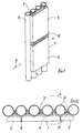
- Figure 1 shows a perspective view of the assembly of the plates 6 according to the invention on the pipes 9 connected by so-called pipe fins 7.
- the spaces between two plates 6 to be assembled are cast with a plastic compound 10.
- Figure 2 shows a cross section of the assembled parts along the section line AA indicated in Figure 1.
- the arrangement of a plurality of plates 6 next to one another on the tubes 9 can be seen here.
- the spaces between the end faces of the plates 6 are also cast with a plastic mass 10.
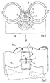
- the anchoring 1 is described in more detail in FIGS. 3 to 5.
- FIG. 3 shows a detail of the detail "A" designated in FIG. 2 and FIGS. 4 and 5 show different views of the anchoring according to the invention.
- the anchoring 1 consists of a web 3, which is welded onto the pipe fin 7, which connects two pipes 9.
- the tab 5 is bent on both sides, so that the angular position " ⁇ " with the bevel of the plates 6th is congruent. As a result, the plates 6 are wedged and the space can be cast with a plastic mass 10.
- Figure 6 shows again all assembly parts in an exploded view.
- the plates 6 can be easily and individually replaced and replaced without having to remove large areas, as in the known methods.
- the subject of the invention namely the disclosed anchoring of curtain stone slabs for tubular steel units also has the leap in progress that overhanging pipe walls can be clad with it.
Landscapes
- Engineering & Computer Science (AREA)
- Mechanical Engineering (AREA)
- General Engineering & Computer Science (AREA)
- Braking Arrangements (AREA)
- Bridges Or Land Bridges (AREA)
- Finishing Walls (AREA)
- Load-Bearing And Curtain Walls (AREA)
- Piles And Underground Anchors (AREA)
- Joining Of Building Structures In Genera (AREA)
Abstract
Description
- Die Erfindung betrifft eine Verankerung von vorgehängten Steinplatten für Stahlrohraggregate.
- Überall dort, wor Rohrleitungen bzw. Stahlrohraggregate mit von außen wirkenden aggressiven Stoffen und/oder Heißgasen in Verbindung kommen können, müssen die Rohrleitungsteile vor der Einwirkung dieser Stoffe und/oder Gase geschützt und abgeschottet werden. Insbesondere in Kessel oder Behälteranlagen, in denen Stahlrohraggregate verlaufen, steht dieses Problem an. Herkömmliche Verfahren, sehen z.B. die Abmauerung zwischen Kesselraum und Rohraggregatteilen vor.
- Es wird auch die Belegung der Rohre durch Steinplatten praktiziert, die großflächig aufgesetzt und vergossen werden.
- Hier hat sich immer wieder gezeigt, daß im Leckagefall oder bei Wartungsarbeiten, die Platten nur schwer zu lösen sind und oftmals große Flächen erneuert werden müssen. Dies erweist sich als sehr arbeits- und kostenintensiv.
- Der Erfindung liegt daher die Aufgabe zugrunde, eine Verankerung für vorgehängte Steinplatten bereitzustellen, die eine einfache Auswechselung der Steinplatten ermöglicht.
- Diese Aufgabe wird erfindungsgemäß dadurch gelöst, daß die Verankerung von vorgehängten Steinplatten für Stahlrohraggregate dadurch gekennzeichnet ist, daß ein auf den Rohrflossen angeordneter mit Bohrung versehener Steg und eine, durch einen Splint arretierte Lasche, die Steinplatten verkeilende Verankerung bilden.
- Eine besonders bevorzugte Ausführungsform ist dadurch gekennzeichnet, daß die mit Langloch versehene Lasche eine beidseitige Abwinkelung aufweist, deren Winkelstellung "α " mit dem Winkel der Steinplatten kongruent ist.
- Eine weitere besonders bevorzugte Ausführungsform ist dadurch gekennzeichnet, daß der Splint vorzugsweise abgewinkelt ist.
- Anhand der beigefügten Zeichnungen, die ein besonders bevorzugtes Ausführungsbeispiel der Erfindung zeigen, wird diese nun näher erläutert. Dabei zeigen:
- Figur 1 eine perspektivische Darstellung der montierten Platten;
- Figur 2 einen Querschnitt entlang der in Figur 1 angedeuteten Schnittlinie A-A;
- Figur 3 ein Detail des in Figur 2 mit "A" bezeichneten Ausschnitts der Verankerung;
- Figur 4 eine Ansicht der Verankerung aus der in Figur 3 angedeuteten Richtung "B";
- Figur 5 eine Ansicht der Verankerung aus der in Figur 4 angedeuteten Richtung "C";
- Figur 6 eine Explosionszeichnung der zu montierenden Einzelteile der Verankerung.
- Figur 1 zeigt eine perspektivische Darstellung der erfindungsgemäßen Montage der Platten 6 auf den durch sogenannte Rohrflossen 7 verbundenen Rohrleitungen 9. Die Zwischenräume zwischen zwei zu montierenden Platten 6 werden mit einer plastischen Masse 10 vergossen.
- Figur 2 zeigt einen Querschnitt der montierten Teile entlang der in Figur 1 angedeuteten Schnittlinie A-A. Es wird hierbei die Anordnung mehrerer Platten 6 nebeneinander auf den Rohren 9 erkennbar.
Die Zwischenräume zwischen den Stirnseiten der Platten 6 werden ebenfalls mit einer plastischen Massen 10 vergossen.
Die Verankerung 1 wird in den Figuren 3 bis 5 näher beschrieben. - Hierbei zeigt Figur 3 ein Detail der in Figur 2 bezeichneten Einzelheit "A" und Figuren 4 und 5 verschiedene Ansichten der erfindungsgemäßen Verankerung.
Die Verankerung 1 besteht aus einem Steg 3, der auf die Rohrflosse 7, die zwei Rohrleitungen 9 verbindet, aufgeschweißt wird. - Eine Lasche 5, die ein Langloch 8 aufweist, wird auf den Steg 3 aufgesetzt und mittels eines vorzugsweise gebogenen Splintes (4), der durch die Bohrung 2 des Steges 3 geführt wird, arretiert.
- Die Lasche 5 ist beidseitig abgebogen, so daß die Winkelstellung "α " mit der Abschrägung der Platten 6 kongruent ist. Dadurch werden die Platten 6 verkeilt und der Zwischenraum kann mit einer plastischen Masse 10 vergossen werden.
- Figur 6 zeigt nochmals alle Montageteile in einer Explosionsdarstellung.
- Im Falle eines Leckagefalls bzw. Wartung der Rohrleitungen 9 oder Beschädigung der Platten 6 können die Platten 6 mühelos, einzeln ausgetauscht und ersetzt werden, ohne daß wie bei den bekannten Verfahren große Flächen entfernt werden müssen.
- Der Erfindungsgegenstand, nämlich die geoffenbarte Verankerung von vorgehängen Steinplatten für Stahlrohraggregate weist ferner den sprunghaften Fortschritt auf, daß mit ihr auch überhängende Rohrwände verkleidet werden können.
Claims (3)
dadurch gekennzeichnet,
daß ein auf den Rohrflossen (7) angeordneter mit Bohrung (2) versehener Steg (3) und eine, durch einen Splint (4) arretierte Lasche (5), die Steinplatten (6) verkeilende Verankerung (1) bilden.
dadurch gekennzeichnet,
daß die mit Langloch (8) versehene Lasche (5) eine beidseitige Abwinkelung aufweist, deren Winkelstellung " α " mit dem Winkel der Steinplatten (6) kongruent ist.
dadurch gekennzeichnet,
daß der Splint (4) vorzugsweise abgewinkelt ist.
Priority Applications (1)
| Application Number | Priority Date | Filing Date | Title |
|---|---|---|---|
| AT88112779T ATE72038T1 (de) | 1987-08-29 | 1988-08-05 | Verankerung von vorgehaengten steinplatten fuer stahlrohraggregate. |
Applications Claiming Priority (2)
| Application Number | Priority Date | Filing Date | Title |
|---|---|---|---|
| DE8711747U DE8711747U1 (de) | 1987-08-29 | 1987-08-29 | Verankerung von vorgehängten Steinplatten für Stahlrohraggregate |
| DE8711747U | 1987-08-29 |
Publications (2)
| Publication Number | Publication Date |
|---|---|
| EP0304705A1 true EP0304705A1 (de) | 1989-03-01 |
| EP0304705B1 EP0304705B1 (de) | 1992-01-22 |
Family
ID=6811566
Family Applications (1)
| Application Number | Title | Priority Date | Filing Date |
|---|---|---|---|
| EP88112779A Expired - Lifetime EP0304705B1 (de) | 1987-08-29 | 1988-08-05 | Verankerung von vorgehängten Steinplatten für Stahlrohraggregate |
Country Status (3)
| Country | Link |
|---|---|
| EP (1) | EP0304705B1 (de) |
| AT (1) | ATE72038T1 (de) |
| DE (2) | DE8711747U1 (de) |
Cited By (3)
| Publication number | Priority date | Publication date | Assignee | Title |
|---|---|---|---|---|
| EP0935113A1 (de) * | 1998-02-04 | 1999-08-11 | Jünger + Gräter GmbH Feuerfestbau | Verankerungsvorrichtung für Stahlrohraggregate abdeckende Steinplatten |
| EP0976997A1 (de) * | 1998-07-27 | 2000-02-02 | Schweiss Service, Detlef Köster GmbH & Co. KG | Wellanker für Feuerfestmaterial |
| EP2302314A1 (de) * | 2009-08-31 | 2011-03-30 | Saint-Gobain Industriekeramik Düsseldorf GmbH | Schutzsystem für eine Ofeninnenwand |
Families Citing this family (5)
| Publication number | Priority date | Publication date | Assignee | Title |
|---|---|---|---|---|
| DE8913040U1 (de) * | 1989-11-04 | 1989-12-21 | Wolff, Ferdinand, 6750 Kaiserslautern | Vorrichtung zum Schutz von Kabeln, Leitungen o.dgl. |
| DE4007662C1 (de) * | 1990-03-10 | 1991-05-23 | Juenger + Graeter Gmbh & Co. Feuerfestbau, 6830 Schwetzingen, De | |
| DE19638711A1 (de) * | 1996-09-21 | 1998-03-26 | Karrena Gmbh | Feuerfeste Verkleidung für etwa waagrecht verlaufende Rohre |
| DE19733998B4 (de) * | 1997-08-06 | 2006-01-26 | Karrena Gmbh | Formsteine für die Auskleidung eines Feuerungsraumes und Feuerungsrauminnenwand |
| FR2785374B1 (fr) * | 1998-10-30 | 2001-01-19 | Lafarge Refractaires Monolithi | Revetement et procede de garnissage d'une paroi d'un appareil thermique et brique et ancrage associes |
Citations (7)
| Publication number | Priority date | Publication date | Assignee | Title |
|---|---|---|---|---|
| US3657851A (en) * | 1970-06-24 | 1972-04-25 | Trw Inc | Two-piece refractory anchor for heavy duty construction |
| DE2112581A1 (de) * | 1971-03-16 | 1972-09-28 | Plibrico Co Gmbh | Feuerfeste Wandkonstruktion |
| DE2804282A1 (de) * | 1978-02-01 | 1979-08-02 | Vni I Pi Otschistke T Gazov St | Kuehler fuer schachtoefen |
| EP0080444A2 (de) * | 1981-11-19 | 1983-06-01 | Höganäs AB | Feuerfeste Auskleidung eines Ofens |
| DE3222755A1 (de) * | 1982-06-18 | 1983-12-22 | Didier-Werke Ag, 6200 Wiesbaden | Verankerungsvorrichtung fuer eine ofenauskleidung |
| US4576532A (en) * | 1983-09-06 | 1986-03-18 | Hanlock, Inc. | Insulation stud |
| US4592688A (en) * | 1983-08-12 | 1986-06-03 | Erico Products, Inc. | Insulation hanger and method |
-
1987
- 1987-08-29 DE DE8711747U patent/DE8711747U1/de not_active Expired
-
1988
- 1988-08-05 DE DE8888112779T patent/DE3867969D1/de not_active Expired - Fee Related
- 1988-08-05 AT AT88112779T patent/ATE72038T1/de not_active IP Right Cessation
- 1988-08-05 EP EP88112779A patent/EP0304705B1/de not_active Expired - Lifetime
Patent Citations (7)
| Publication number | Priority date | Publication date | Assignee | Title |
|---|---|---|---|---|
| US3657851A (en) * | 1970-06-24 | 1972-04-25 | Trw Inc | Two-piece refractory anchor for heavy duty construction |
| DE2112581A1 (de) * | 1971-03-16 | 1972-09-28 | Plibrico Co Gmbh | Feuerfeste Wandkonstruktion |
| DE2804282A1 (de) * | 1978-02-01 | 1979-08-02 | Vni I Pi Otschistke T Gazov St | Kuehler fuer schachtoefen |
| EP0080444A2 (de) * | 1981-11-19 | 1983-06-01 | Höganäs AB | Feuerfeste Auskleidung eines Ofens |
| DE3222755A1 (de) * | 1982-06-18 | 1983-12-22 | Didier-Werke Ag, 6200 Wiesbaden | Verankerungsvorrichtung fuer eine ofenauskleidung |
| US4592688A (en) * | 1983-08-12 | 1986-06-03 | Erico Products, Inc. | Insulation hanger and method |
| US4576532A (en) * | 1983-09-06 | 1986-03-18 | Hanlock, Inc. | Insulation stud |
Cited By (3)
| Publication number | Priority date | Publication date | Assignee | Title |
|---|---|---|---|---|
| EP0935113A1 (de) * | 1998-02-04 | 1999-08-11 | Jünger + Gräter GmbH Feuerfestbau | Verankerungsvorrichtung für Stahlrohraggregate abdeckende Steinplatten |
| EP0976997A1 (de) * | 1998-07-27 | 2000-02-02 | Schweiss Service, Detlef Köster GmbH & Co. KG | Wellanker für Feuerfestmaterial |
| EP2302314A1 (de) * | 2009-08-31 | 2011-03-30 | Saint-Gobain Industriekeramik Düsseldorf GmbH | Schutzsystem für eine Ofeninnenwand |
Also Published As
| Publication number | Publication date |
|---|---|
| EP0304705B1 (de) | 1992-01-22 |
| ATE72038T1 (de) | 1992-02-15 |
| DE8711747U1 (de) | 1987-10-22 |
| DE3867969D1 (de) | 1992-03-05 |
Similar Documents
| Publication | Publication Date | Title |
|---|---|---|
| DE3000670C2 (de) | Feuersichere Leitungsdurchführung | |
| DE4225949C2 (de) | Vorrichtung zum Befestigen einer biegsamen Druckplatte | |
| EP0304705B1 (de) | Verankerung von vorgehängten Steinplatten für Stahlrohraggregate | |
| DE2251498A1 (de) | Haltevorrichtung fuer rohrleitungen, kabel od.dgl | |
| DE2427444C2 (de) | Bauwerksknoten | |
| DE29721146U1 (de) | Verbindungsstück | |
| DE3936003C2 (de) | ||
| DE3608953A1 (de) | Fassadenplattenanker | |
| DE3530987C1 (de) | Rohrbogen mit Schleißbuchsenelementen | |
| DE3122940A1 (de) | Abstandselement fuer bewehrungseinlagen fuer betonwaende | |
| DE2229988C2 (de) | Zaun mit Zaunfeldern aus Baustahl-Bewehrungsmatten | |
| DE9413613U1 (de) | Fugenblech für Betonwandungen | |
| AT358263B (de) | Kantholzverbinder | |
| DE2921480C2 (de) | ||
| EP0976997B1 (de) | Wellanker für Feuerfestmaterial | |
| DE3028553C2 (de) | Vorrichtung zur Verankerung einer Zustellung an den Siederohren eines Feuerraumes | |
| CH532528A (de) | Halter für Aufzug-Führungsschienen | |
| DE896819C (de) | Schraubenlose Rohrschelle zur Befestigung von Rohren, Kabeln, Draehten u. dgl. an einem Schlitzbandeisen | |
| AT2346U1 (de) | Kabelabfangvorrichtung | |
| DE9013433U1 (de) | Vorrichtung zur Fixierung des Abstandes von an einem Träger festzulegenden Rohrleitungen | |
| DE2950651A1 (de) | Halterung fuer rohrregister | |
| DE545803C (de) | Decken- und Dachkonstruktion aus Betonplatten zwischen Traegern aus Eisen und Eisenbeton | |
| DE2153964C3 (de) | Baggerzahn | |
| DE3411458C1 (de) | Befestigen eines Rohres in einer Lochplatte mittels Explosionsdruck | |
| DE7149046U (de) | Ankerschiene |
Legal Events
| Date | Code | Title | Description |
|---|---|---|---|
| PUAI | Public reference made under article 153(3) epc to a published international application that has entered the european phase |
Free format text: ORIGINAL CODE: 0009012 |
|
| AK | Designated contracting states |
Kind code of ref document: A1 Designated state(s): AT BE CH DE ES FR GB GR IT LI LU NL SE |
|
| 17P | Request for examination filed |
Effective date: 19890318 |
|
| 17Q | First examination report despatched |
Effective date: 19910219 |
|
| GRAA | (expected) grant |
Free format text: ORIGINAL CODE: 0009210 |
|
| AK | Designated contracting states |
Kind code of ref document: B1 Designated state(s): AT BE CH DE ES FR GB GR IT LI LU NL SE |
|
| PG25 | Lapsed in a contracting state [announced via postgrant information from national office to epo] |
Ref country code: IT Free format text: LAPSE BECAUSE OF FAILURE TO SUBMIT A TRANSLATION OF THE DESCRIPTION OR TO PAY THE FEE WITHIN THE PRE;WARNING: LAPSES OF ITALIAN PATENTS WITH EFFECTIVE DATE BEFORE 2007 MAY HAVE OCCURRED AT ANY TIME BEFORE 2007. THE CORRECT EFFECTIVE DATE MAY BE DIFFERENT FROM THE ONE RECORDED.SCRIBED TIME-LIMIT Effective date: 19920122 Ref country code: BE Effective date: 19920122 Ref country code: ES Free format text: THE PATENT HAS BEEN ANNULLED BY A DECISION OF A NATIONAL AUTHORITY Effective date: 19920122 Ref country code: GB Effective date: 19920122 Ref country code: GR Free format text: LAPSE BECAUSE OF FAILURE TO SUBMIT A TRANSLATION OF THE DESCRIPTION OR TO PAY THE FEE WITHIN THE PRESCRIBED TIME-LIMIT Effective date: 19920122 Ref country code: SE Effective date: 19920122 |
|
| REF | Corresponds to: |
Ref document number: 72038 Country of ref document: AT Date of ref document: 19920215 Kind code of ref document: T |
|
| REF | Corresponds to: |
Ref document number: 3867969 Country of ref document: DE Date of ref document: 19920305 |
|
| ET | Fr: translation filed | ||
| GBV | Gb: ep patent (uk) treated as always having been void in accordance with gb section 77(7)/1977 [no translation filed] | ||
| PG25 | Lapsed in a contracting state [announced via postgrant information from national office to epo] |
Ref country code: AT Effective date: 19920805 |
|
| PG25 | Lapsed in a contracting state [announced via postgrant information from national office to epo] |
Ref country code: LU Free format text: LAPSE BECAUSE OF NON-PAYMENT OF DUE FEES Effective date: 19920831 |
|
| PLBE | No opposition filed within time limit |
Free format text: ORIGINAL CODE: 0009261 |
|
| STAA | Information on the status of an ep patent application or granted ep patent |
Free format text: STATUS: NO OPPOSITION FILED WITHIN TIME LIMIT |
|
| 26N | No opposition filed | ||
| PGFP | Annual fee paid to national office [announced via postgrant information from national office to epo] |
Ref country code: DE Payment date: 19970729 Year of fee payment: 10 Ref country code: FR Payment date: 19970729 Year of fee payment: 10 |
|
| PGFP | Annual fee paid to national office [announced via postgrant information from national office to epo] |
Ref country code: CH Payment date: 19970805 Year of fee payment: 10 |
|
| PGFP | Annual fee paid to national office [announced via postgrant information from national office to epo] |
Ref country code: NL Payment date: 19970831 Year of fee payment: 10 |
|
| PG25 | Lapsed in a contracting state [announced via postgrant information from national office to epo] |
Ref country code: LI Free format text: LAPSE BECAUSE OF NON-PAYMENT OF DUE FEES Effective date: 19980831 Ref country code: CH Free format text: LAPSE BECAUSE OF NON-PAYMENT OF DUE FEES Effective date: 19980831 |
|
| PG25 | Lapsed in a contracting state [announced via postgrant information from national office to epo] |
Ref country code: NL Free format text: LAPSE BECAUSE OF NON-PAYMENT OF DUE FEES Effective date: 19990301 |
|
| REG | Reference to a national code |
Ref country code: CH Ref legal event code: PL |
|
| PG25 | Lapsed in a contracting state [announced via postgrant information from national office to epo] |
Ref country code: FR Free format text: LAPSE BECAUSE OF NON-PAYMENT OF DUE FEES Effective date: 19990430 |
|
| NLV4 | Nl: lapsed or anulled due to non-payment of the annual fee |
Effective date: 19990301 |
|
| PG25 | Lapsed in a contracting state [announced via postgrant information from national office to epo] |
Ref country code: DE Free format text: LAPSE BECAUSE OF NON-PAYMENT OF DUE FEES Effective date: 19990601 |
|
| REG | Reference to a national code |
Ref country code: FR Ref legal event code: ST |