EP0303082B1 - Streufahrzeug - Google Patents
Streufahrzeug Download PDFInfo
- Publication number
- EP0303082B1 EP0303082B1 EP88111805A EP88111805A EP0303082B1 EP 0303082 B1 EP0303082 B1 EP 0303082B1 EP 88111805 A EP88111805 A EP 88111805A EP 88111805 A EP88111805 A EP 88111805A EP 0303082 B1 EP0303082 B1 EP 0303082B1
- Authority
- EP
- European Patent Office
- Prior art keywords
- spreading
- vehicle
- loading
- distributing plate
- silo
- Prior art date
- Legal status (The legal status is an assumption and is not a legal conclusion. Google has not performed a legal analysis and makes no representation as to the accuracy of the status listed.)
- Expired - Lifetime
Links
Images
Classifications
-
- E—FIXED CONSTRUCTIONS
- E01—CONSTRUCTION OF ROADS, RAILWAYS, OR BRIDGES
- E01C—CONSTRUCTION OF, OR SURFACES FOR, ROADS, SPORTS GROUNDS, OR THE LIKE; MACHINES OR AUXILIARY TOOLS FOR CONSTRUCTION OR REPAIR
- E01C19/00—Machines, tools or auxiliary devices for preparing or distributing paving materials, for working the placed materials, or for forming, consolidating, or finishing the paving
- E01C19/12—Machines, tools or auxiliary devices for preparing or distributing paving materials, for working the placed materials, or for forming, consolidating, or finishing the paving for distributing granular or liquid materials
- E01C19/20—Apparatus for distributing, e.g. spreading, granular or pulverulent materials, e.g. sand, gravel, salt, dry binders
- E01C19/201—Apparatus for distributing, e.g. spreading, granular or pulverulent materials, e.g. sand, gravel, salt, dry binders with driven loosening, discharging or spreading parts, e.g. power-driven, drive derived from road-wheels
- E01C19/202—Apparatus for distributing, e.g. spreading, granular or pulverulent materials, e.g. sand, gravel, salt, dry binders with driven loosening, discharging or spreading parts, e.g. power-driven, drive derived from road-wheels solely rotating, e.g. discharging and spreading drums
- E01C19/203—Centrifugal spreaders with substantially vertical axis
Definitions
- the invention relates to a spreading vehicle with a spreading device built on a loading platform, in particular a silo spreading device, in which the spreading material is automatically removed from a silo container and fed via a discharge chute to a spreading plate arranged at the rear, a device being provided which independently of the spreading distance of the spreading material thrown from the spreading plate the loading of the gritting vehicle or the filling of the silo container keeps essentially constant.
- EP-A-0071291 which discloses a spreading vehicle according to the preamble of claim 1, to solve this problem it is proposed to mount the spreading plate on a trolley which is pulled behind the spreading vehicle. As a result, the spreading disc is supported on the road surface. Regardless of the loading of the silo container and the deflection of the vehicle body, the spreading disc should always be kept at the same distance above the road surface in this way.
- the generic spreading vehicle constructed in this way is however unusable for practical use; because on the one hand the trolley performs uncontrolled vertical and roll movements due to unevenness in the road to be sprinkled, and on the other hand obstacles of even low heights cannot be passed with the generic spreading vehicle without that there is a risk that the support of the trolley equipped with the support wheel breaks off. The latter is particularly true when reversing.
- the present invention has for its object to provide a spreading vehicle of the generic type, in which the spreading width can be kept approximately constant during operation even with changing loads, which is suitable for practical use.
- This approach ensures an automatic adaptation of the dropping conditions from the spreading disc, which is also suitable for practical use, in such a way that an approximately constant spreading width can be maintained regardless of the change in the loading of the spreading vehicle.
- the spreading width is kept constant according to the invention despite increasing lifting of the spreading plate relative to the ground in that the speed of the spreading plate decreases accordingly, the centrifugal forces acting on the spreading material being reduced.
- Another essential prerequisite of the teaching according to the invention is the ongoing and automatic determination of a measured variable, preferably proportional to the increasing emptying of the grit container, preferably the distance between the grit plate and the ground or grit plate and vehicle axle.
- a control signal is generated via a control device, to the input of which the measurement signal is connected, with which a control variable, namely the speed of the spreading disc, is changed in the sense of a reduction.
- the distance measurement can be carried out in the context of the invention by means of a measuring device, which can either be with a mechanical probe or without contact, e.g. using ultrasound, sonar, laser beam or the like.
- the ongoing measurement of the loading or unloading state of the silo container can, for. B. by more or less deeply immersed in the grit, by measuring the vibration amplitudes of the loading platform or - particularly simply - by counting the number of revolutions of the screw conveyor taking into account the initial filling level of the silo container.
- the invention achieves a constant spreading density, i. H. it is ensured that the spreading density does not decrease with increasing emptying of the grit container. Increasing the spreading plate and the associated increase in the spreading width with a constant supply quantity would otherwise result in an increase in the spreading area and thereby a reduction in the spreading density per m2.
- the constant spreading width achieved according to the invention is a very significant advantage under the current spreading requirements because it opens up the possibility of setting the spreading density to a minimum without fear of it being undershot.
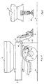
- Fig. 1 two alternative measuring devices are each shown schematically, with which an output signal corresponding to the deflection of the loading platform (1) is generated.
- a first alternative for measuring the platform height is an electronic measuring device (10), which measures the distance from the floor (9) z. B. by means of a laser beam (11).
- a second alternative is a mechanical measuring device (12) which measures the change in distance between the loading platform (1) and the vehicle axle (2) by means of a feeler lever (13) which is articulated on the differential housing (14).
- both types of measuring devices require damping or smoothing in such a way that vibrations of the vehicle body due to bumps on uneven road surfaces are suppressed.
- the spreading disc While the normal discharge height of the spreading disc (6) is set at around 30 cm when the silo container (3) is fully loaded, the spreading disc can be raised by approx. 15 to 20 cm during operation as it is discharged. In the horizontal direction, without the device according to the invention, this would mean an undesirable increase in the originally set maximum spreading width from approx. 3 m to approx. 4 m.
- the device provided according to the invention keeps the spreading width constant in that the speed of the spreading disc (6) decreases in accordance with the relief of the spreading vehicle.
Landscapes
- Engineering & Computer Science (AREA)
- Architecture (AREA)
- Civil Engineering (AREA)
- Structural Engineering (AREA)
- Road Paving Machines (AREA)
- Filling Or Emptying Of Bunkers, Hoppers, And Tanks (AREA)
- Transition And Organic Metals Composition Catalysts For Addition Polymerization (AREA)
- Polishing Bodies And Polishing Tools (AREA)
Applications Claiming Priority (2)
| Application Number | Priority Date | Filing Date | Title |
|---|---|---|---|
| DE3726946 | 1987-08-13 | ||
| DE19873726946 DE3726946A1 (de) | 1987-08-13 | 1987-08-13 | Streufahrzeug |
Publications (2)
| Publication Number | Publication Date |
|---|---|
| EP0303082A1 EP0303082A1 (de) | 1989-02-15 |
| EP0303082B1 true EP0303082B1 (de) | 1995-09-27 |
Family
ID=6333642
Family Applications (1)
| Application Number | Title | Priority Date | Filing Date |
|---|---|---|---|
| EP88111805A Expired - Lifetime EP0303082B1 (de) | 1987-08-13 | 1988-07-22 | Streufahrzeug |
Country Status (3)
| Country | Link |
|---|---|
| EP (1) | EP0303082B1 (OSRAM) |
| AT (1) | ATE128502T1 (OSRAM) |
| DE (2) | DE3726946A1 (OSRAM) |
Cited By (1)
| Publication number | Priority date | Publication date | Assignee | Title |
|---|---|---|---|---|
| CN110786164A (zh) * | 2019-09-26 | 2020-02-14 | 扬州大学 | 一种多功能修剪作业机 |
Families Citing this family (8)
| Publication number | Priority date | Publication date | Assignee | Title |
|---|---|---|---|---|
| DE4025099C1 (en) * | 1990-08-08 | 1991-06-27 | Mercedes-Benz Aktiengesellschaft, 7000 Stuttgart, De | Height controller for fertiliser or insecticide spreader - has signal source with filtering stage for suppressing fast precautions in output signal |
| FR2700507B1 (fr) * | 1993-01-20 | 1995-03-10 | Acometis | Dispositif d'épandage, notamment, de sel, de semence, d'engrais et autre. |
| DE102004059462B4 (de) * | 2004-12-10 | 2009-11-05 | Schmidt Holding Gmbh | Winterdienst-Streufahrzeug |
| EP1775387B1 (de) * | 2005-10-13 | 2016-12-07 | Küpper-Weisser GmbH | Winterdienststreuvorrichtung |
| EP1775386A1 (de) * | 2005-10-13 | 2007-04-18 | Küpper-Weisser GmbH | Winterdienststreuvorrichtung |
| EP1775385B1 (de) * | 2005-10-13 | 2016-06-29 | Küpper-Weisser GmbH | Winterdienststreuvorrichtung |
| CN108149633B (zh) * | 2018-02-19 | 2019-08-02 | 扬州市杭集创意设计园有限公司 | 一种公路防护栏杆融雪盐喷洒机 |
| GB2624285B (en) * | 2023-09-15 | 2024-12-04 | Econ Engineering Ltd | Distributor apparatus |
Family Cites Families (6)
| Publication number | Priority date | Publication date | Assignee | Title |
|---|---|---|---|---|
| DE2111612A1 (de) * | 1971-03-11 | 1972-09-14 | Langen & Co | Niveauregelsystem fuer Kraftfahrzeuge |
| DE2456424A1 (de) * | 1973-02-02 | 1976-06-16 | Volkswagenwerk Ag | Achsniveauregelung eines fahrzeuges, insbesondere eines kraftfahrzeuges |
| DE2606899A1 (de) * | 1976-02-20 | 1977-09-01 | Bosch Gmbh Robert | Regeleinrichtung fuer eine einrichtung zum bestreuen von strassen und dergleichen mit einem streugut |
| IT1144447B (it) * | 1981-07-29 | 1986-10-29 | Pietro Regaldo | Impianto composto di apparecchiature polivalenti erogatrici di sostanze per il trattamento di piani stradali o terreni avente la possibilita di caricamento autonomo dell impianto da terra sul pianale di un mezzo trasportatore e viceversa |
| US4595072A (en) * | 1983-10-27 | 1986-06-17 | Daniel Barnea | Vehicle suspension system |
| US4583693A (en) * | 1984-09-17 | 1986-04-22 | Harder Kenneth A | Dump body spreader |
-
1987
- 1987-08-13 DE DE19873726946 patent/DE3726946A1/de active Granted
-
1988
- 1988-07-22 AT AT88111805T patent/ATE128502T1/de not_active IP Right Cessation
- 1988-07-22 EP EP88111805A patent/EP0303082B1/de not_active Expired - Lifetime
- 1988-07-22 DE DE3854514T patent/DE3854514D1/de not_active Expired - Fee Related
Cited By (1)
| Publication number | Priority date | Publication date | Assignee | Title |
|---|---|---|---|---|
| CN110786164A (zh) * | 2019-09-26 | 2020-02-14 | 扬州大学 | 一种多功能修剪作业机 |
Also Published As
| Publication number | Publication date |
|---|---|
| DE3726946C2 (OSRAM) | 1989-05-18 |
| DE3726946A1 (de) | 1989-02-23 |
| EP0303082A1 (de) | 1989-02-15 |
| DE3854514D1 (de) | 1995-11-02 |
| ATE128502T1 (de) | 1995-10-15 |
Similar Documents
| Publication | Publication Date | Title |
|---|---|---|
| EP0303082B1 (de) | Streufahrzeug | |
| EP3017674B1 (de) | Verfahren zur massenstrombestimmung bei einer verteilmaschine | |
| EP0667415A1 (de) | Strassenfertiger | |
| EP2753525A1 (de) | Partikelstreuanlage für ein schienenfahrzeug | |
| DE10231525A1 (de) | Verfahren und Vorrichtung zur Schlupfsimulation auf Fahrzeugprüfständen | |
| DE602004011483T2 (de) | Anordnung und verfahren zur schätzung der höhe des schwerpunkts eines fahrzeugs | |
| EP3081067B1 (de) | Verfahren zur regelung des streugut-massenstromes von scheibenstreuern, scheibenstreuer und verwendung eines verteilerscheibensatzes hierfür | |
| DE102019120535A1 (de) | Landwirtschaftlicher Anhänger mit automatischer Stützlasteinstellung | |
| EP1863974B1 (de) | Streufahrzeug für den winterdienst | |
| DE102020119431A1 (de) | Streumaschine | |
| DE2758435C3 (de) | Gleisgebundener Wagen für Transport und Streuung von Schüttgut, insbesondere Böschungsmaterial | |
| DE10034797C1 (de) | Streugerät | |
| DE10145927A1 (de) | Zentrifugaldüngerstreuer | |
| EP4066614A1 (de) | Streufahrzeug mit geteiltem kratzboden und variabler geschwindigkeitsregulierung | |
| DE4201300A1 (de) | Verfahren und vorrichtung zur steuerung der ausbringmenge | |
| EP1417880A2 (de) | Aufnahmevorrichtung für Futter an Futtermischwagen | |
| DE4003766A1 (de) | Einrichtung zur erkennung des federungsverhaltens eines federelements, insbesondere fuer ein luftgefedertes fahrzeug | |
| EP1674306B1 (de) | Landwirtschaftliche Arbeitsmaschine | |
| DE102016122298A1 (de) | Verteilmaschine mit kapazitiver Füllstandserfassungsvorrichtung und Verfahren zum Betreiben der kapazitiven Füllstandserfassungsvorrichtung | |
| DE102021103451A1 (de) | Verfahren zum Ausbringen von Streugut mittels eines landwirtschaftlichen Streugeräts | |
| DE3149650A1 (de) | Brueckenkratzer fuer direkte materialaufgabe | |
| DE102021207262B4 (de) | Strandreinigungsfahrzeug | |
| DE112004000648B4 (de) | Anordnung zum Abschätzen der Geschwindigkeit eines Fahrzeuges mit Hilfe eines korrigierten Radradius | |
| EP4066613A1 (de) | Streufahrzeug mit verschiebbaren streutellern | |
| DE2803053A1 (de) | Vorrichtung zum fortlaufenden auffuellen von graeben, aushebungen u.dgl. mit material |
Legal Events
| Date | Code | Title | Description |
|---|---|---|---|
| PUAI | Public reference made under article 153(3) epc to a published international application that has entered the european phase |
Free format text: ORIGINAL CODE: 0009012 |
|
| AK | Designated contracting states |
Kind code of ref document: A1 Designated state(s): AT CH DE FR GB IT LI NL SE |
|
| 17P | Request for examination filed |
Effective date: 19890307 |
|
| 17Q | First examination report despatched |
Effective date: 19900427 |
|
| RAP1 | Party data changed (applicant data changed or rights of an application transferred) |
Owner name: SCHMIDT HOLDING EUROPE GMBH |
|
| GRAA | (expected) grant |
Free format text: ORIGINAL CODE: 0009210 |
|
| AK | Designated contracting states |
Kind code of ref document: B1 Designated state(s): AT CH DE FR GB IT LI NL SE |
|
| REF | Corresponds to: |
Ref document number: 128502 Country of ref document: AT Date of ref document: 19951015 Kind code of ref document: T |
|
| ITF | It: translation for a ep patent filed | ||
| GBT | Gb: translation of ep patent filed (gb section 77(6)(a)/1977) |
Effective date: 19950928 |
|
| REF | Corresponds to: |
Ref document number: 3854514 Country of ref document: DE Date of ref document: 19951102 |
|
| ET | Fr: translation filed | ||
| PGFP | Annual fee paid to national office [announced via postgrant information from national office to epo] |
Ref country code: GB Payment date: 19960708 Year of fee payment: 9 |
|
| PGFP | Annual fee paid to national office [announced via postgrant information from national office to epo] |
Ref country code: SE Payment date: 19960719 Year of fee payment: 9 |
|
| PGFP | Annual fee paid to national office [announced via postgrant information from national office to epo] |
Ref country code: NL Payment date: 19960730 Year of fee payment: 9 |
|
| PLBE | No opposition filed within time limit |
Free format text: ORIGINAL CODE: 0009261 |
|
| STAA | Information on the status of an ep patent application or granted ep patent |
Free format text: STATUS: NO OPPOSITION FILED WITHIN TIME LIMIT |
|
| 26N | No opposition filed | ||
| PG25 | Lapsed in a contracting state [announced via postgrant information from national office to epo] |
Ref country code: GB Free format text: LAPSE BECAUSE OF NON-PAYMENT OF DUE FEES Effective date: 19970722 |
|
| PG25 | Lapsed in a contracting state [announced via postgrant information from national office to epo] |
Ref country code: SE Effective date: 19970723 |
|
| PG25 | Lapsed in a contracting state [announced via postgrant information from national office to epo] |
Ref country code: NL Free format text: LAPSE BECAUSE OF NON-PAYMENT OF DUE FEES Effective date: 19980201 |
|
| GBPC | Gb: european patent ceased through non-payment of renewal fee |
Effective date: 19970722 |
|
| NLV4 | Nl: lapsed or anulled due to non-payment of the annual fee |
Effective date: 19980201 |
|
| EUG | Se: european patent has lapsed |
Ref document number: 88111805.3 |
|
| PGFP | Annual fee paid to national office [announced via postgrant information from national office to epo] |
Ref country code: AT Payment date: 19980723 Year of fee payment: 11 |
|
| PGFP | Annual fee paid to national office [announced via postgrant information from national office to epo] |
Ref country code: CH Payment date: 19980724 Year of fee payment: 11 |
|
| PGFP | Annual fee paid to national office [announced via postgrant information from national office to epo] |
Ref country code: FR Payment date: 19990517 Year of fee payment: 12 |
|
| PG25 | Lapsed in a contracting state [announced via postgrant information from national office to epo] |
Ref country code: AT Free format text: LAPSE BECAUSE OF NON-PAYMENT OF DUE FEES Effective date: 19990722 |
|
| PG25 | Lapsed in a contracting state [announced via postgrant information from national office to epo] |
Ref country code: LI Free format text: LAPSE BECAUSE OF NON-PAYMENT OF DUE FEES Effective date: 19990731 Ref country code: CH Free format text: LAPSE BECAUSE OF NON-PAYMENT OF DUE FEES Effective date: 19990731 |
|
| PGFP | Annual fee paid to national office [announced via postgrant information from national office to epo] |
Ref country code: DE Payment date: 19990924 Year of fee payment: 12 |
|
| REG | Reference to a national code |
Ref country code: CH Ref legal event code: PL |
|
| PG25 | Lapsed in a contracting state [announced via postgrant information from national office to epo] |
Ref country code: FR Free format text: LAPSE BECAUSE OF NON-PAYMENT OF DUE FEES Effective date: 20010330 |
|
| REG | Reference to a national code |
Ref country code: FR Ref legal event code: ST |
|
| PG25 | Lapsed in a contracting state [announced via postgrant information from national office to epo] |
Ref country code: DE Free format text: LAPSE BECAUSE OF NON-PAYMENT OF DUE FEES Effective date: 20010501 |
|
| PG25 | Lapsed in a contracting state [announced via postgrant information from national office to epo] |
Ref country code: IT Free format text: LAPSE BECAUSE OF NON-PAYMENT OF DUE FEES;WARNING: LAPSES OF ITALIAN PATENTS WITH EFFECTIVE DATE BEFORE 2007 MAY HAVE OCCURRED AT ANY TIME BEFORE 2007. THE CORRECT EFFECTIVE DATE MAY BE DIFFERENT FROM THE ONE RECORDED. Effective date: 20050722 |
|
| APAH | Appeal reference modified |
Free format text: ORIGINAL CODE: EPIDOSCREFNO |