EP0301697A2 - Verfahren und Vorrichtung zur Herstellung einer im Querschnitt verformten Rohrauskleidung. - Google Patents
Verfahren und Vorrichtung zur Herstellung einer im Querschnitt verformten Rohrauskleidung. Download PDFInfo
- Publication number
- EP0301697A2 EP0301697A2 EP88305688A EP88305688A EP0301697A2 EP 0301697 A2 EP0301697 A2 EP 0301697A2 EP 88305688 A EP88305688 A EP 88305688A EP 88305688 A EP88305688 A EP 88305688A EP 0301697 A2 EP0301697 A2 EP 0301697A2
- Authority
- EP
- European Patent Office
- Prior art keywords
- liner
- pipe
- section
- cross
- tubular cross
- Prior art date
- Legal status (The legal status is an assumption and is not a legal conclusion. Google has not performed a legal analysis and makes no representation as to the accuracy of the status listed.)
- Granted
Links
Images

Classifications
-
- B—PERFORMING OPERATIONS; TRANSPORTING
- B29—WORKING OF PLASTICS; WORKING OF SUBSTANCES IN A PLASTIC STATE IN GENERAL
- B29C—SHAPING OR JOINING OF PLASTICS; SHAPING OF MATERIAL IN A PLASTIC STATE, NOT OTHERWISE PROVIDED FOR; AFTER-TREATMENT OF THE SHAPED PRODUCTS, e.g. REPAIRING
- B29C53/00—Shaping by bending, folding, twisting, straightening or flattening; Apparatus therefor
- B29C53/02—Bending or folding
- B29C53/08—Bending or folding of tubes or other profiled members
- B29C53/086—Bending or folding of tubes or other profiled members bending radially, i.e. deformig the cross-section of the tube
-
- B—PERFORMING OPERATIONS; TRANSPORTING
- B29—WORKING OF PLASTICS; WORKING OF SUBSTANCES IN A PLASTIC STATE IN GENERAL
- B29C—SHAPING OR JOINING OF PLASTICS; SHAPING OF MATERIAL IN A PLASTIC STATE, NOT OTHERWISE PROVIDED FOR; AFTER-TREATMENT OF THE SHAPED PRODUCTS, e.g. REPAIRING
- B29C63/00—Lining or sheathing, i.e. applying preformed layers or sheathings of plastics; Apparatus therefor
- B29C63/26—Lining or sheathing of internal surfaces
- B29C63/34—Lining or sheathing of internal surfaces using tubular layers or sheathings
- B29C63/343—Lining or sheathing of internal surfaces using tubular layers or sheathings the tubular sheathing having a deformed non-circular cross-section prior to introduction
-
- B—PERFORMING OPERATIONS; TRANSPORTING
- B29—WORKING OF PLASTICS; WORKING OF SUBSTANCES IN A PLASTIC STATE IN GENERAL
- B29C—SHAPING OR JOINING OF PLASTICS; SHAPING OF MATERIAL IN A PLASTIC STATE, NOT OTHERWISE PROVIDED FOR; AFTER-TREATMENT OF THE SHAPED PRODUCTS, e.g. REPAIRING
- B29C67/00—Shaping techniques not covered by groups B29C39/00 - B29C65/00, B29C70/00 or B29C73/00
- B29C67/0014—Shaping techniques not covered by groups B29C39/00 - B29C65/00, B29C70/00 or B29C73/00 for shaping tubes or blown tubular films
-
- F—MECHANICAL ENGINEERING; LIGHTING; HEATING; WEAPONS; BLASTING
- F16—ENGINEERING ELEMENTS AND UNITS; GENERAL MEASURES FOR PRODUCING AND MAINTAINING EFFECTIVE FUNCTIONING OF MACHINES OR INSTALLATIONS; THERMAL INSULATION IN GENERAL
- F16L—PIPES; JOINTS OR FITTINGS FOR PIPES; SUPPORTS FOR PIPES, CABLES OR PROTECTIVE TUBING; MEANS FOR THERMAL INSULATION IN GENERAL
- F16L57/00—Protection of pipes or objects of similar shape against external or internal damage or wear
Definitions
- This invention relates to the use of thermoplastic liners within pipe lines, either initially or as a repair, for protecting the internal walls from deterioration.
- the liner restores the fluid transporting capability of the piping and prevents further interior deterioration.
- One such liner for protecting the interior of pipe is taught by French Patent No. 81 07346 dated April 13, 1981.
- the present method of manufacturing a deformed tube product involves a first step of extruding a pipe liner having a tubular cross-section, and a second step of deforming the extruded tube into a reduced cross-section for insertion into a pipe as a liner therefor.
- a feature of this method of manufacturing a tube product is the use of thermoplastic material and its temperature control at the successive stages of formation, during extrusion into its initial and subsequent form, during its deformation, and during its return to ambient usable condition upon installation into the pipe.
- the liner configuration has an outside diameter equal to or slightly greater than the inside diameter of the pipe to be protected, whereby the liner is either unstressed or under slight circumferential compression; either of which conditions is readily accommodated by the plastic liner which relies upon the surrounding pipe for its structural support.
- controlled heat is applied to establish a softened condition of the thermoplastic material after its extrusion, while simultaneously applying deforming tools thereto in order to reduce its cross-sectional configuration.
- heat is withdrawn and the finished product of continuous length is then stored on spools for storage, transport and subsequent installation.
- U-shaped reduced tubular configuration is particularly shown and described, it is to be understood that a V-shape or other cross-sectional configurations may be used, whether they be H-shaped or X-shaped, or the like.
- the U-shape, or V-shape is presently considered to be the most practical and preferred configuration for such a tube product.
- the deformation of the initially extruded tube progresses in a gradual manner, by shaping means. That is, at least one side of the tubular extrusion is increasingly depressed so as to condition the tubular extrusion for its lateral collapse into a reduced U-shaped, or V-shaped cross-sectional form; thus providing a deformed tube.
- this deformation is conducted in the presence of controlled heat substantially below fluidity of the thermoplastic material and such that the plastic is deformed without adversely effecting its structural integrity, whether in its deformed condition or in its subsequently re-established initial condition.
- rollers are used to deform the initially extruded tube.
- the deformation is gradual, step by step, utilizing combined pairs of opposed shaping rollers.
- a feature hereof is the lateral collapse of the tubular extrusion over a forming rail, by means of opposed shaping rollers that embrace the forming rail.
- the finished product is then cooled to ambient temperature during and/or upon its delivery from the forming rail, as by means of a cooling trough. Heating and cooling is by means of heat adsorption or radiant heating, and preferably by temperature controlled water baths or spray.
- the present day commercial demand for this pipe liner is a product ranging from 2 inches to 24 inches in diameter.
- the wall thickness will vary in proportion to diameter as circumstances require. Accordingly, there will be variations in the process steps involving the plurality of shaping means disclosed herein as shaping rollers and back-up roller, whereby at least one side of the tubular extrusion is deformed as required. That is, the number of shaping means and the step by step degree of deformation is variable, depending upon the size and wall thickness and material to be deformed.
- a feature of this method and apparatus is that the product is pulled out of the extruder and from the deforming tool, for delivery to a storage spool, in a controlled manner, whereby the cross-sectional configuration of the deformed tube product is uniform and within specified dimensional tolerance.
- the product herein disclosed is a thermoplastic pipe liner that is reduced from its initially extruded cross-section, so that it can be easily pulled inside a pipe line and then restored to its initially extruded cross-section.
- the outside diameter of the initially extruded and/or reformed liner tube is the same or slightly greater than the inside diameter of the pipe that receives it, so that the liner exterior comes into perfect interface contact with the pipe interior and preferably under slight circumferential compression.
- This interface contact of liner within and with the pipe eliminates any annulus therebetween, and so that the requirement of filling such an annulus is virtually eliminated.
- a feature of this liner is its thin-wall configuration made of a thermoplastic such as polyethylene, nylon, TeflonTM, ABS, or any other such plastic material, whereby the small loss of inside diameter of the flow passage is largely compensated for by the exceptional flow coefficient within the liner made of such a thermoplastic material.
- a thermoplastic such as polyethylene, nylon, TeflonTM, ABS, or any other such plastic material
- expensive pipe materials such as stainless alloys can be substituted with ordinary steel pipe, and lined with this product liner, thereby realizing a cost saving of 1.5 to 2.2, together with the improved fluid tolerance properties of the plastic which can be selected to best advantage. Accordingly, pipe lines which are structurally sound need not be replaced, since this product liner can be installed and replaced as circumstances require.
- the method and apparatus herein disclosed for the manufacture of this product liner involves the primary step of extruding thermoplastic tubing, and the secondary step of deforming the thermoplastic tubing.
- the primary step of extrusion involves generally, an extruder that receives raw plastic material and delivers a tubular cross-section through a vacuum trough that controls the processing temperature and precise configuration of the tubular cross-section.
- the secondary step of deforming the precise tubular cross-section involves generally, a multi-stage shaping tool that deforms the extrusion at controlled temperature and delivers it through a cooling trough as the finished product liner.
- the finished product liner is drawn from the secondary step by a puller that controls the linear speed of the production and maintains a constant wall thickness of the finished product liner.
- the present invention also relates to an improved method and apparatus for installing the temporarily deformed pipe liner within a pipeline, expanding the deformed liner to its original cylindrical shape, taking additional steps causing the liner to conform even more precisely to the interior contour of the pipe, and flaring opposite ends of the liner into engagement with respective radially directed pipe flanges.
- pipe is used hereinafter to refer to single, individual lengths of pipe, as well as to a plurality of individual lengths joined together to form a pipeline or section of pipeline.
- pipe refers to any one or more lengths of pipe to be lined in accordance with this invention.
- the open ends of the pipe or pipes, which define the overall length to be lined are provided with conventional radial flanges to facilitate attachment to adjacent pipe sections. Such flanges are also utilized in conjunction with the installation process and apparatus of this invention as explained in greater detail below.
- the cleaning and threading operations may be effected by a single brush pig of conventional design.
- the brush pig is utilized to pass the pilot or pulling line through the pipe.
- a manifold which opens into the pipe at one end and which is closed by a removable flange at the other end, is applied to each end of the pipe, via the above-described radial flanges and fasteners such as bolts or the like.
- the inside diameter of the process manifold is larger than the outside diameter of the liner, to aid in the removal of the manifold after the expansion process.
- the same manifold size is also used as a "pigging station.” Prior to attaching the manifold at the upstream end, the brush pig is introduced into the manifold, and a pulling or pilot line is fed into a vent in the manifold and attached to the trailing end of the pig.
- the downstream manifold is opened and the pig removed.
- the pulling line is then attached to a downstream winch or other suitable winding device.
- the upstream manifold is opened and the pilot or pulling line cut from the supply reel.
- the line is then drawn through the open manifold and attached to a lead end of the U-shaped liner.
- the U-shaped liner may then be pulled from its own supply reel into the pipe via actuation of the downstream winch or other suitable winding device.
- a multiple stage process may be required to thread the final pulling line through the pipe.
- the pressure build-up in the pipe may not be sufficient to push the pig and, at the same time, pull a line or cable of the required strength through the pipe.
- a relatively light, so-called "fishing line” is initially threaded through the pipe by a relatively lightweight pig, followed by one or more increasingly stronger lines, drawn by larger pigs, until the final pulling line or cable is drawn through the pipe.
- the liner is drawn into the pipe via the downstream winch, it is cut to an appropriate length, such that a relatively short section of liner extends beyond either end of the pipe, i.e., to approximately the length of the pipe section itself plus upstream and downstream manifolds at either end.
- packer/expander assemblies are introduced into the manifolds to seal the liner ends and to mechanically initiate expansion of the liner.
- fluid preferably hot liquid from a closed boiler system, is supplied through one of the packer/expander assemblies and into the pipe to reheat the liner to a temperature which is to be above the raw materials' crystallization point, for example, 260°F, when using Union Carbide Polyethylene raw material.
- an outlet valve in the manifold opposite that through which the hot liquid is supplied is left partially open to allow the hot liquid to flow through, until the desired temperature is achieved.
- the liner Once the liner has reached a temperature above the raw materials' crystallization temperature, it will begin to assume its original cylindrical shape. At the same time, pressure within the liner rises, preferably to about 7 bars in a first pressurizing stage.
- the outlet valve is adjusted so that the pressure within the liner is increased in a second stage to about 15 bars to cause the liner to conform more precisely to the inner surface contours of the pipe.
- the second-stage pressure application can be considered optional and will depend on the condition of the pipe to be lined as well as the wall thickness of the liner.
- the packer/expander assemblies are removed after the hot liquid, such as water, is emptied from the pipe through a valve in the manifold.
- a calibrated pig is then introduced into the upstream manifold to traverse the pipeline while the liner is still hot, and to apply a radially outwardly directed force about the circumference of the liner to squeeze out any remaining air between the liner and pipe used thereby ensure even further conformance to the inner pipe wall, including weldments and other surface irregularities.
- This second pig is driven through the pipeline with cold water which tends to to "freeze" the liner in place.
- pipes of between 2 and 24 inches in diameter, and as long as two miles or more may be fitted with a continuous liner to provide ideal corrosion protection in both new and existing corroded pipes.
- the pipe liner is constructed of high density polyethylene (HDPE), which may be a Union Carbide DGDB-2480 Black 4865 compound meeting the requirements of ASTM 1248-81a for Type PE 34 Class C product. It is characterized by a high level of environmental stress cracking resistance and high strength. Nylon, TeflonTM, ABS or any other such plastic material may also be utilized.
- HDPE high density polyethylene
- Nylon, TeflonTM, ABS or any other such plastic material may also be utilized.
- the preferred HDPE liner material has been tested with over 280 chemicals that might be expected to flow through a pipeline and the following observations have been reported relating to the above identified HDPE which are particularly relevant to this invention:
- a pig is then inserted into the pipe to mechanically reform the liner into a generally cylindrical configuration.
- the pig is preferably inserted at the downstream end of the pipe (although it may be inserted at the upstream end) and a pressurized fluid, either a gas or liquid but preferably a gas, such as air, is introduced into the pipe behind the pig.
- a backpressure is provided at the upstream end of the pipe.
- the fluid behind the pig may be pressurized to about 25 to 150 p.s.i., while the upstream end of the pipe may be pressurized to about 5 to 40 p.s.i.
- the pig As the pig travels through the liner, it reforms the liner into its original cylindrical shape.
- the liner is maintained under internal pressure for a predetermined time, for example, on the order of about 30 minutes. The pressure is then relieved, the pigs and the manifolds are both removed, the opposite ends of the liner are flared, all as described previously, and service to the pressure fluid is restored.
- such service is reconnected within a relatively short period of time, on the order of about 24 hours or less, so that the interior of the liner is repressurized by the pressure of the service fluid to maintain the liner in generally cylindrical form bearing against the inner walls of the pipe. Consequently, the pressure will ensure that the liner conforms to the existing pipe and, over time, all stresses are relieved such that the liner will remain substantially cylindrical even when the service pressure is removed.
- the foregoing described method of relining pressurized pipelines may be applied to non-pressurized pipe, provided the liner is maintained under pressure over a predetermined time. For example, maintaining the pressure for a time on the order of 3 to 4 weeks will in most cases ensure that the liner returns and is retained in its prior cylindrical configuration. For shorter periods of time, for example, less than one week, the liner may not return to and be retained in its perfectly cylindrical configuration. However, sufficient stress is relieved in such shorter period of time such that the liner will be maintained generally cylindrical.
- the capacity to return to and to retain its generally cylindrical original configuration is a function of the diameter, material and wall thickness of the liner. Thus, the greater the diameter and/or thickness, the greater the time period the liner should be maintained under pressure in order to return to and to be retained in its original cylindrical configuration. The converse is also true.
- the invention as described herein has applications to many types of pipeline, including water and mud injection; oil and gas; vapors and fumes; saltwater; utility sewage and drainage; gas gathering and distribution, etc.
- a method for producing a deformed pipe liner of tubular cross-section having an outside diameter to fit into a pipe line and formed of plastic material for subsequent insertion into a pipe line and then reformed to the cross-section wherein the improved method is characterized by firstly collapsing the tubular cross-section at a deformable portion thereof by folding it by depression diametrically toward an opposite side portion thereof along a plane of bilateral symmetry about which opposite side sections of the tubular cross-section bend into double-wall configurations with the fold juxtaposed to the opposite side portion of the tubular cross-section, secondly collapsing the opposite side sections of double-wall configurations laterally toward the plane of bilateral symmetry by bending the double-wall configuration of the opposite side sections, thereby reducing the cross-sectional configuration without elongation and for insertion into the pipe line and reformation therein to its initial tubular cross-section to fit within the pipe line.
- an apparatus for producing a deformed pipe liner having a tubular cross-section and formed of plastic material for subsequent insertion into a pipe line and then reformed to the extruded cross-section to fit the inside diameter of the pipe line wherein the improved apparatus is characterized by at least one revolvable back-up roller disposed on a horizontal axis parallel to the axis of and in opposition to at least one revolvable shaping roller, the back-up roller having a concave spool-shaped periphery centered at a plane of bilateral symmetry to engage a back-up portion of the tubular cross-section, the shaping roller having a convex fold initiating and fold shaping perimeter at the plane of bilateral symmetry to depress a deformable portion of the tubular cross-section diametrically toward the back-up portion thereof and along the plane of bilateral symmetry about which opposite side sections of the tubular cross-section bend into double wall configurations with a fold thereof juxtaposed
- a further preferred embodiment of the present invention provides a process for installing a hollow cylindrical thermoplastic liner in a pipe wherein the process is characterized by the steps of altering the cross-sectional shape of the liner to reduce the cross-sectional dimension thereof at a shape memory activation temperature of about 160-180°F, pulling the altered liner into the pipe such that the tubular liner extends beyond opposite ends of the pipe, reheating the liner to the memory activation temperature to cause the liner to return to the cylindrical cross-sectional size and shape and, subsequently, increasing pressure within the liner to cause the liner to conform to interior contours of the pipe.
- a still further preferred embodiment of the invention provides a process for installing a thermoplastic liner in a substantially round pipe having inside and outside diameters wherein the process is characterized by forming at a first elevated temperature a thermoplastic liner having a cylindrical shape and an outside diameter larger than the inside diameter of the pipe, temporarily deforming the cylindrical liner at a second elevated temperature to an altered cross-sectional configuration which reduces the cross-sectional dimension of the liner by about 25%, cooling the liner to ambient temperature, inserting the liner in the pipe, reheating the liner to at least the second elevated temperature to cause the liner to return to the cylindrical shape and applying additional expansion forces to the liner to substantially conform the liner to the pipe.
- a still further preferred embodiment of the present invention provides a process for installing a thermoplastic liner in a pipe comprising the steps of providing a hollow generally cylindrical liner formed of thermoplastic material, altering the cross-sectional shape of the liner to reduce the cross-sectional dimension thereof, disposing the altered liner into said pipe such that the liner extends beyond the opposite ends of the pipe, mechanically reforming the liner to cause the liner to return to its generally cylindrical cross-section and bear against the inner walls of the pipe and pressurizing the interior of the liner from end to end and for a predetermined time to maintain the liner against the interior walls of the pipe and to relieve the stresses in the liner tending to cause the liner to return to its altered shape.
- this invention is concerned with lining new and old pipe lines with a deformed tube that is pulled into the pipe line and then reformed to tightly fit therein.
- the tube can be made of any suitable material which will collapse and subsequently return to its original cross-section, i.e., a plastic.
- the pipe liner is a thin-walled plastic sleeve extruded in continuous lengths and later inserted into pipe lines for internal protection; for example to protect new pipe lines and to reconstitute deteriorated pipe lines as well.
- the pipe liner L as it is disclosed herein is initially extruded so as to have an exterior diameter at least as large as the interior diameter of the pipe into which it is to be inserted, and preferably slightly in excess of said pipe diameter in order that the tubular pipe liner L is under slight circumferential compression when it is in operating position in the pipe line.
- a feature of this invention is the deformation of the tubular pipe liner L, to decrease its cross-section configuration for storage and to facilitate its insertion into a pipe. That is, the original cylinder cross-section of the pipe liner L is collapsed and later restored, all without destroying its dimensional properties. Therefore, the circular configuration of the pipe liner L is not stretched, even though the material is plastic and subject to flow.
- the original cylindrical cross-section properties of the initially extruded pipe liner L are preserved in its deformed condition which enables its insertion into pipe lines and for its subsequent reformation into its original cylindrical cross-section.
- the characteristic feature of this invention is that the initially extruded thermoplastic pipe liner L is shaped and thereby deformed without elongation, whereby its dimensional properties necessary for restoration are retained.
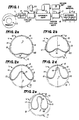
- the initially extruded configuration is cylindrical, having inner and outer diameter walls 10 and 11.
- an upper back-up section 12 and a lower deformable section 13.
- the deformation is bilaterally symmetrical and disposed about a vertical plane a of symmetry and about which the tube formation is collapsed by means of bending and folding.
- there are opposite side sections 14 and 15 which are established by a center fold 16 that inverts the lower deformable section 13 upwardly into juxtaposed relation to the inside diameter 10 of the back-up section 12.
- each side section is comprised of a side wall depending from top dead center of the tube form and bent inwardly so as to continue upwardly to the center fold 16. It is significant that the two side sections 14 and 15 are thereby collapsed into double wall configurations which are further collapsed inwardly toward the center plane a of symmetry as clearly shown in Figure 2e which is the desired product formation.
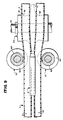
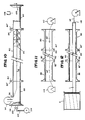
- FIG. 1 of the drawings the entire method of tube formation and deformation is illustrated in its general form.
- an extruder means E followed by a cooling means C1 that delivers the tube form into a deformer apparatus D which performs the product deformation process.
- the product is then delivered through cooling means C2 so as to establish it at ambient temperature for delivery through a puller means P and onto a storage spool S or the like.
- the extruder means E is state of the art and receives the raw thermoplastic material and forces it through an extrusion die 17 at, for example, 350° to 440°F using heating means 18 to attain that temperature.
- the cooling means C1 is state of the art, and preferably a vacuum cooling means supported by a vacuum cooling unit 19 and reducing the tube form temperature to, for example, 260°F.
- the deformer apparatus D is subjected to heat control means H that maintains this necessary deformation temperature of, for example, 260°F.
- the cooling means C2 is state of the art and reduces the tube form temperature to ambient, and it is supported, for example, by a cooling tower 20 or the like. During the cooling period, the shape of the deformed liner is to be maintained until the pipe reaches an ambient temperature. This shape can be maintained by outside pressure such as rollers, caterpillars, or straps, or maintained by an internal vacuum.
- the means C1 and C2 include pump means for water recirculation, and it is to be understood that the aforementioned temperatures can vary as circumstances require.
- Puller means P is also state of the art and draws the finished deformed tube product from the preceding apparatus, its pulling force being controlled so as not to stretch or compress the tube form in the process of its deformation, and thereby controlling its wall thickness.
- a cylindrical tube form is extruded as shown by phantom lines in Figures 2a through 2e, thereby establishing a uniform wall section, and preferably of cylindrical configuration.
- the top semi-circular portion, namely the back-up section 12 is supported and the fold 16 is impressed at bottom dead center of the tube form in alignment with the center plane of symmetry and progressing upwardly and into juxtaposed relation to the inside wall 10 of the tube form at top dead center thereof.
- the deformation process can be performed on any angle, such as prescribed above on a dead center bottom, but also from its side, top or any other angle.
- the opposite side sections 14 and 15 are turned and/or bent inwardly at their lower extremities 21 and 22, so that the walls thereof continue upwardly within their respective inside walls 10 and to the fold 16 (see Figures 2a through 2d).
- the fold 16 is formed by bending the tube form inwardly at bottom dead center thereof for collapse along the center plane of symmetry. Simultaneously with this collapse, the lower extremities 21 and 22 of the side sections 14 and 15 are also inwardly bent as above described.
- collapse of the tube form is preferred in a multiplicity of steps, in order to conform gradually to the changing configuration of the tube form and without elongation of its cross-sectional configuration.
- collapse as thus far described can be accomplished in a single step, for example in small diameter tubing. As shown, however, there are four steps of collapse along the center line a of symmetry, and each of which has back-up against the top section 12, it being the bottom section 13 that is deformed.
- the first step of collapse shown in Figure 2a initiates the fold 16 by bending and commences to bend the lower extremities 21 and 22.
- the succeeding three steps of Figures 2b and 2c and 2d progressively and increasingly bend and move the fold 16 close to the inside wall 10 at the top dead center of the tube form and simultaneously increasingly and progressively bend and move the lower extremities 21 and 22 upwardly as shown.
- the tubular cross-section is reduced in its sectional configuration.
- a final step of collapse is performed by bending the opposite side sections 14 and 15 inwardly toward the center plane of symmetry, in order to reduce the arcuate configuration of said two side sections and so that they occur within the radius or outside diameter of the initial tube form, and so as to clear within the inside diameter of the pipe line into which the ultimate pipe liner L is inserted.
- a feature of this final collapsing step is bringing together the two lower extremities 21 and 22 into juxtaposed relation to the center plane of symmetry, and preferably closer together than the continuing tube walls upstanding therefrom to the bends of fold 16.
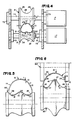
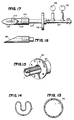
- the shaping rollers R1-R4 are lowermost, there being back-up rollers B1, B2 and B3 to support the tube form as it is impressed upon by the said rollers R1-R4. As shown, the rollers R1-R4 and B1-B3 are on spaced and parallel horizontally disposed and transverse axes.
- Back-up roller B1 is disposed over the shaping roller R1 (see Figure 4) and is characterized by its concaved spool-shape 25 at the center plane of symmetry and conforming to the substantially semi-circular back-up section 12 of the tube form.
- Back-up roller B1 has opposite flaring side flanges that embrace the initial formation of the side sections 14 and 15 of the tube form.
- Shaping roller R1 (see Figure 4) is characterized by its convex fold initiating and shaping perimeter 27 at the center plane of symmetry to depress the tube form wall upwardly at bottom dead center.
- Shaping roller R1 has opposite concave side flanges 28 that embrace the initial formation of the lower extremities 21 and 22 of the side sections 14 and 15. The perimeters of roller flanges 26 and 28 are closely related so as to capture the tube form therebetween.
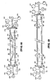
- Back-up roller B2 is disposed over and intermediate shaping rollers R2 and R3 (see Figure 3) and is characterized by its concaved spool shape 35 at the center plane of symmetry and conforming to the substantially semi-circular back-up section 12 of the tube form.
- Back-up roller B2 has opposite flaring flanges 36, to a lesser extent than that of roller B1, to embrace the formation of the side sections 14 and 15 of the tube form.
- Shaping roller R2 (see Figure 5) is characterized by its convex fold shaping perimeter 37 at the center plane of symmetry to further shape the tube form wall upwardly along said plane of symmetry. Shaping roller R2 has opposite concaved side flanges 38 that embrace the lower extremities 21 and 22 of the side sections 14 and 15. The perimeters of roller flanges 36 and 38 are somewhat spaced and guide the tube form therebetween.
- Shaping roller R3 (see Figure 6) is characterized by its convex fold shaping perimeter 47 at the center plane of symmetry to further shape the tube form wall upwardly along said plane of symmetry.
- Shaping roller R3 has opposite concaved side flanges 48, of lesser extent than roller R2, that embrace the lower extremities 21 and 22 of the side sections 14 and 15.
- the perimeters of roller flanges 36 and 48 are somewhat spaced and guide the tube form therebetween.
- Back-up roller B3 (see Figure 7) is disposed over shaping roller R4 and is characterized by its concaved spool-shape 55 at the center plane of symmetry and conforming to the substantially semi-circular back-up section 12 of the tube form.
- Back-up roller B3 has minimized side flanges 56 that embrace the side sections 14 and 15 of the tube form.
- Shaping roller R4 (see Figure 7) is characterized by its most sharply convexed fold shaping perimeter 57 at the center plane of symmetry to still further shape the tube form wall along said plane of symmetry.
- Shaping roller R4 has opposite concaved side flanges 58, of still lesser extent than roller R3, that embrace the lower extremities 21 and 22 of the side sections 14 and 15.
- the perimeters of roller flanges 56 and 58 are closely related so as to capture and guide the tube form therebetween.
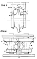
- the fifth and final collapsing step is performed by a pair of laterally positioned shaping rollers S1 and S2 disposed at opposite sides of the tube form as it emanates from shaping roller R4 (see Figures 8 and 9).
- Rollers S1 and S2 are to reduce the arcuate cross-section of back-up section 12 of the tube form, as shown. Accordingly, the rollers S1 and S2 are disposed on spaced and parallel vertical axes and are characterized by a concave spool shape 60 of curvilinear configuration increasing in curvature from top dead center, each roller, from the initial full radius of the tube form to the smaller radius of the lower extremities 21 and 22.
- the rollers S1 and S2 have top and bottom flanges 61 and 62 which are peripherally juxtaposed so as to completely capture the finally collapsed and deformed tube form, thereby establishing the product pipe liner L.
- the tube form of pipe liner L is finally collapsed onto a rail R disposed between the shaping rollers S1 and S2.
- the rail R is of a cross-sectional configuration to conform with the inside walls of the side sections 14 and 15 and of the lower extremities 21 and 22. Accordingly, and as clearly shown, the final cross-sectional configuration of the pipe liner L is established.
- the rail R has sliding engagement with the tube form and is of substantial longitudinal extent so as to enable a reduction in temperature and firming up while being held in the required cross-sectional configuration.
- rail R Note particularly the hourglass cross-section of the rail R that accommodates the aforementioned collapsing of the lower extremities 21 and 22, bringing them closer together in relation to the center plane of symmetry than the upstanding inner walls extending to the bends of fold 16.
- rail R is optional depending on the shape to be defined. If a precise curvature 16 is necessary, the rail R will aid in keeping such a shape. This rail R, for example, would be necessary for the bud fusion of the deformed pipe.
- the shaping of the tube form is gradual and progressive (see Figures 3 and 9) and from Figure 1 it will be observed that the temperature control is involved, and the preferred material involved is a thermoplastic. Accordingly, and as best illustrated in Figure 3 of the drawings, there are water nozzles 70 that dispense tempered water so as to maintain the temperature of, for example, 210°F in order to soften the plastic material and to ensure its bending properties. Other heat sources such as hot air or radiant heat can be incorporated to obtain the desired temperature of the pipe, which is to be above the raw materials' crystallization point. Nozzles 70 disseminate hot water into the area of the shaping rollers R1 through R4 and S1 and S2.
- the tube form is made plastic so as to be shaped and bent into the desired deformed condition.
- the shape enabling temperature of the plastic tube form is reduced to ambient by water nozzles 71 that dispense tempered water at lower temperature so as to cool the finished pipe liner L to, for example, 70°F, all as shown in Figures 1 and 3 of the drawings.
- the tempered water is collected in a sump or pan 72 for its recirculation as shown in Figure 1.
- the cooling means C2 reduces the tube form to ambient temperature on or passing into delivery from the rail R.
- rollers B1-B3, R1-R4 and S1 and S2 are free to turn on bearings 73 and thereby enable forward motion of the tube form through the apparatus as described.
- torque means M in the form of motors M electrical or hydraulic, provide the assist required (see Figure 4).
- anti-friction bearings 73 are provided with shafting 74, all as is shown throughout the drawings.
- a tubular pipe line L is provided that is reduced in cross-sectional configuration so as to be readily inserted into pipe lines and then reformed to its initially extruded cross sectional configuration, whereby it properly fits into the pipe line for which it is designed, all as differing circumstances require.
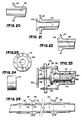
- a cylindrical section 80 of pipe to be lined is shown.
- the pipe is formed with radial flanges 82, 84 at either end to enable connection with adjacent pipe sections in a conventional manner.
- While the pipe lining procedure is shown primarily in schematic form, it will be understood that the pipe may be lined above ground or, in situ, underground or underwater. In any or all of the above cases, it may be necessary to disconnect the pipeline at selected, longitudinally spaced access points and, if continuous pipeline flow is required, splice in a bypass section between pipe sections on either side of the section to be lined. This bypassing or splicing procedure forms no part of the present invention and need not be described further.
- the pipe section Before commencing the lining operation, the pipe section should be inspected to determine its ability to withstand pressures applied during the lining operation. Of course, if the pipe is damaged, corroded, etc. to the point of not being able to withstand such pressures, then the pipe section in question must to be replaced rather than lined.
- the interior of the pipe 80 may be cleaned by a conventional brush pig 86 designed to traverse the pipe interior with brushes extending radially into contact with the interior pipe wall, to effect removal of loose material, residue, sediment, and the like which might otherwise negatively impact the lining process.
- a conventional brush pig 86 designed to traverse the pipe interior with brushes extending radially into contact with the interior pipe wall, to effect removal of loose material, residue, sediment, and the like which might otherwise negatively impact the lining process.
- upstream and downstream manifolds 88 and 90 are attached to the pipe flanges 82, 84, respectively.
- the manifolds are provided with abutting flanges 82′, 84′ and connection is achieved via bolts or other suitable fasteners in conjunction with aligned apertures ( Figure 25) in the respective flanges.
- a pulling or pilot line 92 fed from a reel 94 through a vent hole 96 in the manifold 88, is attached to the trailing end of the pig 86 before closure of the upstream manifold 88.
- the upstream manifold 88 has a closed end 98 which comprises a removable plate, and in which is mounted an inlet valve 100.
- the valve 100 is connected via conduit 102 to a pressurized air or liquid source 104.
- the downstream manifold 90 is also provided with an end plate which mounts a relief valve 106.
- a pressure gauge 108 monitors pressure within the pipe.
- Pressurized air or water is introduced through a valve 100 into the pipe behind the pig 86, so as to push the brush pig and pulling line 92 through the pipe to the downstream end thereof.
- relief valve 106 is set at about 100 psi to ensure proper degassing of the pipe as the pig moves to the downstream end of the pipe.
- the pig 86 reaches the downstream end, and moves into the manifold 90, the interior pressure of the pipe is gradually released, manifolds 88 and 90 are opened, and pig 86 removed. Thereafter, line 92 may be drawn out and subsequently fastened to an associated winch or reel 110 as shown in Figure 11.
- the pipe section 80 is shown with manifolds 88 and 90 opened at their remote ends and with an initial lightweight fishing line 92 connected to a heavier gauge pulling or pilot line 112.
- Lines 92 and 112 are pulled through the pipeline 80 by winch 110 located adjacent the downstream end of the pipeline 80 and manifold 90.
- the pilot line 112 is unwound from a reel 114 at the upstream end of the pipeline section.
- the requirement for progressively stronger pilot or pulling lines is necessitated only if the pipeline section to be lined is of great length or, if there is an inability to build up sufficient pressure, by reason of leakage for example, in the existing pipeline, to push the pig 86 and associated fishing or pilot line through the pipe section.
- the appropriate gauge pulling line may be cut adjacent the upstream manifold 88 and thereafter attached to the temporarily deformed U-shaped liner L, as more clearly illustrated in Figure 12.
- the pulling line 112 is connected to the U-shaped liner L by a suitable gripping arrangement shown in schematic form at 116 in Figure 12.
- the gripping means 116 is of the radial expansion type so as to prevent damage to the end of the liner.
- the U-shaped liner L may be unwound from a storage or supply reel S which is located adjacent the upstream manifold.
- the liner may be temporarily deformed at the factory and shipped in continuously wound reels S or, where the diameter of the originally extruded pipe is so large as to make such predeformation and shipment impractical, mobile deforming apparatus may be provided at the site for deforming the liner L in situ and pulling it through the pipe section to be lined in one continuous operation.
- a mobile deforming apparatus may be provided constituting the same principle as the apparatus disclosed in this invention, with the exception that the heating device before deforming will be extended to raise the temperature of the now ambient round pipe to past its crystallization point. In other words, the benefit of an already warm pipe (out of the extruders' vacuum trough) is not available working with a mobile deforming tool.
- Figure 13 illustrates a cross-sectional view of pipeline section 80 with the liner L in its finally expanded form. This is to contrasted with the cross-sectional view of the pipe liner L in Figure 14 which illustrates it in its temporarily deformed U-shape.
- Figure 15 a perspective view illustrates the temporarily deformed U-shaped liner L after it is pulled through the pipe section 80 to be lined.
- the liner L extends approximately to the open ends of the manifolds 88 and 90 to not only facilitate the expansion process, but also to leave sufficient liner to form radial flanges in a manner to be described in greater detail below.
- FIG 16 there is schematically shown a representation of the initial expansion of the liner L within the pipe 80.
- a pair of mechanical expansion/packer assemblies are inserted into the liner from either end of the upstream and downstream manifolds 88, 90.
- the packer/expander assemblies 120, 122 are identical in every respect and, therefore, only one need be described in detail.
- the downstream packer/expander 122 assembly includes an inlet conduit or manifold 124 operatively connected to a closed boiler 126 through which hot liquid may be introduced into the liner via valve 128.
- the temperature of the liquid is monitored by a conventional gauge 130, while the pressure within the liner is monitored by a conventional pressure gauge 132.
- Inlet pipe 124 is connected via pipe extension 124′ to a cylindrical packer assembly 134 consisting of conventional packing rings which are sized to seal off the liner relative to the manifold 90 to prevent any escape of liquid from the liner through the manifold.
- a cylindrical wedge-like expander 136 provided with a tapered surface 138, extends forward of the packer assembly and serves to force the liner end back into a cylindrical shape, as best seen in Figure 16.
- a similar arrangement is provided at the upstream manifold 88 so that the liner L is initially expanded mechanically at both ends in the above described manner.
- the expander 136 is provided with an internal bore 140 ( Figures 17 and 18) which operatively connects to the inlet conduit 124 and closed boiler 126. It will thus be appreciated that expander 136 only initiates the expansion process, while facilitating introduction of hot liquid through the bore 140 and into the liner L.
- hot water is introduced from the source 126 into the interior of the liner. Because the system is closed, the hot water may be raised to high temperatures without the creation of steam and, in this initial stage, the hot water is introduced into the liner so as to raise the temperature of the liner above its crystallization point.
- a relief valve 144 in the packer/expander assembly 120 allows hot water to flow continuously through the liner, at a first pressure of about 7 bars. It will be appreciated that the period of time required to reheat the liner to its shape memory temperature at the first pressure will depend on the diameter and length of the pipe to be lined.
- the U-shaped memory of the liner is erased and the liner tends to assume its original cylindrical shape.
- the now cylindrical liner L may not conform exactly to the inner surface of the pipe which may be warped, particularly over extended distances. Accordingly the pressure inside the liner is raised in a second stage to about 15 bars to expand the liner L into substantially exact conformance with the interior surface of the pipe 80, as illustrated in Figure 19.
- the process manifold is further equipped with an air outlet (air leak) that enables the air or liquid which might have been trapped between the liner and the original pipe to escape. This is another reason why the manifold is slightly oversized as compared to the 0.D. of the liner.
- valve 128 is closed, hot water supply 126 disconnected, and the hot water within the pipe is emptied.
- the packer/expander assemblies 120, 122 are then withdrawn.
- a conventional expansion pig having a diameter substantially identical to the inside diameter of the expanded liner, is introduced into the pipe 80 and is pushed through the pipe section applying a radial force to the liner so as squeeze any remaining air from between the pipe and liner so as to conform 100% of the liner surface against the interior surface of the pipe.
- the pig is preferably driven by a supply of cold water which more or less "freezes" the plastic into final form behind the pig, eliminating all air spaces between the liner and the pipe section.
- source 126 may be operatively connected to the upstream assembly 120 as well.
- manifolds 88, 90 and assemblies 120, 122, including conduit 124 are provided with the necessary inlets, outlets for monitoring devices, relief valves, and the like so that, in effect, they are interchangeable.
- Figure 22 shows the expanded liner L extending beyond pipe 80, with the manifold 88 removed.
- the liner will be trimmed in accordance with predetermined and calculated data establishing the length of liner required to produce a given size radial flange for pipes of various diameters.
- a first flaring stage commences wherein the liner end is heated, by an air gun for example, to about 180-200°F, and flange 148 is partially formed at an angle of about 50 to about 70°, relative to horizontal, as shown in Figure 21.
- the specific angle will depend on factors such as the diameter of the pipe, the flange length, and so on.
- Figure 23 illustrates an exemplary flaring tool for carrying out the first and second flaring stages as described above.
- a manually operated screw jack 150 is fastened at at least two locations, preferably 180° apart, about the pipe flange 82.
- a pair of heavy duty bolts 152 extend between bolt holes formed in the flange 82 and a cross bar 154.
- Bar 154 is provided with a threaded aperture 156, intermediate the ends thereof, for receiving a threaded jack member 158 which mounts a flaring tool 160, a packing assembly 162, a washer 164 and a nut 166 on one side of the cross bar 154, and a handle 168 on the other side of the cross bar.
- the speed with which the flaring tools are brought into engagement with the liner end or ends must be correlated to the pipe diameter, temperature, etc. to prevent damage to the end or ends.
- the flaring tools do not engage the liner end or ends, until the temperature, monitored by conventional means, reaches the predetermined level.
- the tools remain in full pressure engagement with the liner end or ends during the respective cooling steps.
- screw jack 150 may be hydraulically actuated, particularly for larger diameter pipes.
- FIG 26 there is illustrated a plurality of adjacent pipes 80, each having an individual liner L applied in accordance with the above described process.
- the formation of radial flanges 148 on each liner section results in a continuous interior lining with no pipe exposure to the materials flowing through the pipeline.
- This of course is an alternative to introducing a single continuous liner through a plurality of single pipe sections, but with similarly effective results.
- That pressure may, in accordance with the present invention, comprise the pressure of the liquid in the pipe when in normal service. Consequently, after the interior of the pipe to be lined is cleaned by the conventional brush pig 86, the manifolds 88 and 90 are in place and the deformed liner is inserted into the pipe, the liner can be mechanically reformed to its original, generally cylindrical shape with the use of a pig and applied pressure.
- the ends of the manifolds are initially deformed as previously described and the pig is inserted, preferably at the downstream end.
- the pig may be conventional and may comprise a medium density foam.
- a fluid under pressure for example, air under a pressure between about 25 and 150 p.s.i., depending on the pipe size and length, is introduced behind the plug at the downstream end.
- a back pressure or vacuum pressure is provided at the upstream end of the pipe, for example, on the order of about 5 to 40 p.s.i., again depending upon the length and size of the pipe.
- the pig Because of the differential pressure applied to the pig, the pig advances from the downstream end of the pipe to the upstream end, mechanically reforming the pipe to its generally cylindrical configuration as it moves between those ends. Upon arrival at the upstream end, the pressure is maintained behind the pig throughout the length of the pipe and liner for a predetermined time interval, for example, about 30 minutes. The pipe liner is then depressurized and both manifolds and the pig are removed. Both ends of the liner are subsequently flared, as described previously, and the fluid service is reconnected.
- the foregoing lining process may be used for lines that are not normally under pressure, provided the pressure is maintained within the liner for the predetermined time necessary to relieve the stresses in the liner tending to deform the liner to its initial deformed shape.
- the time required is a function of the diameter wall thickness and material of the liner and the degree of circularity required. For example, if an expanded but non-cylindrical configuration of the liner in the pipe is acceptable, the time period during which the liner is held under pressure may be less than one week. On the other hand, such time period should be on the order of 3-4 weeks if a perfectly cylindrical liner is required.
Landscapes
- Engineering & Computer Science (AREA)
- Mechanical Engineering (AREA)
- General Engineering & Computer Science (AREA)
- Manufacturing & Machinery (AREA)
- Lining Or Joining Of Plastics Or The Like (AREA)
- Extrusion Moulding Of Plastics Or The Like (AREA)
- Shaping Of Tube Ends By Bending Or Straightening (AREA)
- Protection Of Pipes Against Damage, Friction, And Corrosion (AREA)
Applications Claiming Priority (6)
| Application Number | Priority Date | Filing Date | Title |
|---|---|---|---|
| US07/077,883 US4863365A (en) | 1987-07-27 | 1987-07-27 | Method and apparatus for deforming reformable tubular pipe liners |
| US77883 | 1987-07-27 | ||
| US114949 | 1987-10-30 | ||
| US07114949 US4985196B1 (en) | 1987-10-30 | 1987-10-30 | Pipe liner process |
| US188468 | 1988-04-29 | ||
| US07188468 US4986951B1 (en) | 1987-07-27 | 1988-04-29 | Pipe liner process |
Publications (4)
| Publication Number | Publication Date |
|---|---|
| EP0301697A2 true EP0301697A2 (de) | 1989-02-01 |
| EP0301697A3 EP0301697A3 (en) | 1990-10-17 |
| EP0301697B1 EP0301697B1 (de) | 1994-06-08 |
| EP0301697B2 EP0301697B2 (de) | 1999-08-11 |
Family
ID=27373183
Family Applications (1)
| Application Number | Title | Priority Date | Filing Date |
|---|---|---|---|
| EP19880305688 Expired - Lifetime EP0301697B2 (de) | 1987-07-27 | 1988-06-22 | Verfahren und Vorrichtung zur Herstellung einer im Querschnitt verformten Rohrauskleidung. |
Country Status (12)
| Country | Link |
|---|---|
| EP (1) | EP0301697B2 (de) |
| JP (1) | JP2728266B2 (de) |
| CN (1) | CN1016407B (de) |
| AU (1) | AU610196B2 (de) |
| BR (1) | BR8803717A (de) |
| CA (1) | CA1312716C (de) |
| CH (1) | CH679845A5 (de) |
| DE (1) | DE3889992T3 (de) |
| EG (1) | EG18534A (de) |
| ES (1) | ES2054808T5 (de) |
| HK (1) | HK19695A (de) |
| RU (1) | RU2039314C1 (de) |
Cited By (17)
| Publication number | Priority date | Publication date | Assignee | Title |
|---|---|---|---|---|
| GB2227545A (en) * | 1989-01-04 | 1990-08-01 | Subterra Ltd | Lining pipes |
| GB2227543A (en) * | 1988-12-22 | 1990-08-01 | Victaulic Plc | Lining pipework |
| WO1992001552A1 (de) * | 1990-07-25 | 1992-02-06 | Manfred Schmidt | Verfahren zum innenverkleiden von rohrleitungen |
| DE4109663A1 (de) * | 1991-03-23 | 1992-09-24 | Meyer & John Gmbh & Co | Verfahren zur sanierung von leitungen durch druckdichte auskleidung mit thermoplastischem kunststoff |
| GB2218490B (en) * | 1988-04-13 | 1992-12-02 | Nu Pipe Inc | Method and apparatus for installing a replacement pipe in an existing underground conduit |
| EP0514142A3 (en) * | 1991-05-17 | 1993-01-13 | Subterra Limited | Apparatus and methods of producing a deformed pipe |
| WO1994012336A1 (en) * | 1992-11-23 | 1994-06-09 | Wavin B.V. | Method for lining a pipeline, in particular a sewer |
| NL9600014A (nl) * | 1988-04-13 | 1997-04-01 | Nu Pipe | Werkwijze en inrichting voor het installeren van een vervangingspijp in een bestaande ondergrondse leiding. |
| WO1999024748A1 (en) * | 1997-11-07 | 1999-05-20 | Spiral Tube Makers Pty. Ltd. | Encased piping system |
| ES2131430A1 (es) * | 1994-03-11 | 1999-07-16 | Pipelining Products Inc | Metodo para revestir nuevamente conducciones preexistentes, aparato deformador y metodo correspondientes e inserto de tubo utilizado. |
| CN110936597A (zh) * | 2018-09-21 | 2020-03-31 | 哈尔滨工业大学 | 一种形状记忆补偿管及用于制作该补偿管的赋型模具 |
| CN112022168A (zh) * | 2020-07-30 | 2020-12-04 | 温州医科大学附属第二医院、温州医科大学附属育英儿童医院 | 一种小白鼠断尾采血器 |
| CN113510921A (zh) * | 2021-04-01 | 2021-10-19 | 魏成浩 | 一种高压液压胶管生产系统及生产工艺 |
| CN113803559A (zh) * | 2016-02-01 | 2021-12-17 | 美国瑞塞卡派普有限责任公司 | 用于恢复受损管的组件 |
| US20220018694A1 (en) * | 2020-07-07 | 2022-01-20 | Oil & Gas Measurement Limited | Device for measuring fluid flow |
| CN114083786A (zh) * | 2021-11-19 | 2022-02-25 | 上海合辉电子元件有限公司 | 一种拉伸模辅助定型组件 |
| US20220381593A1 (en) * | 2019-10-22 | 2022-12-01 | Endress+Hauser Flowtec Ag | Method for producing a measuring tube for a flowmeter |
Families Citing this family (27)
| Publication number | Priority date | Publication date | Assignee | Title |
|---|---|---|---|---|
| JPH0247042A (ja) * | 1988-08-09 | 1990-02-16 | Sekisui Chem Co Ltd | 複合管の製造方法 |
| JPH0257323A (ja) * | 1988-08-22 | 1990-02-27 | Osaka Gas Co Ltd | 管内面のライニング方法 |
| JPH07115410B2 (ja) * | 1990-06-28 | 1995-12-13 | 住友金属工業株式会社 | ポリオレフィン樹脂管による内面ライニング方法 |
| JPH04231792A (ja) * | 1990-12-27 | 1992-08-20 | Sumitomo Metal Ind Ltd | ポリオレフィン樹脂の形状保持・回復方法とその応用 |
| JPH0717011B2 (ja) * | 1991-04-12 | 1995-03-01 | 日本鋼管工事株式会社 | 樹脂パイプ導入方法及び樹脂パイプ導入装置 |
| JPH07119058B2 (ja) * | 1991-05-13 | 1995-12-20 | 日本鋼管工事株式会社 | ライニング工法 |
| RU2122147C1 (ru) * | 1997-02-18 | 1998-11-20 | АОЗТ "Росфлекс" | Способ изготовления гибкой трубы |
| ATE238490T1 (de) | 1997-08-08 | 2003-05-15 | Kobelco Constr Machinery Ltd | Kühlvorrichtung für eine baumaschine |
| JP3494860B2 (ja) * | 1997-10-09 | 2004-02-09 | 東京瓦斯株式会社 | 管路の内張り工法 |
| DE19963056C2 (de) * | 1999-12-24 | 2002-06-06 | Rehau Ag & Co | Verfahren und Vorrichtung zum mehrstufigen Umformen eines Rohres |
| JP2003112366A (ja) * | 2001-10-05 | 2003-04-15 | Sekisui Chem Co Ltd | 管路用塩化ビニル系樹脂ライナー材の製造方法 |
| JP2003112365A (ja) * | 2001-10-05 | 2003-04-15 | Sekisui Chem Co Ltd | 管路用塩化ビニル系樹脂ライナー材の製造方法 |
| CA2604236C (en) * | 2005-04-13 | 2011-01-25 | Baker Hughes Incorporated | Self-conforming screen |
| GB0517385D0 (en) * | 2005-08-26 | 2005-10-05 | Victrex Mfg Ltd | Polymeric materials |
| JP6154709B2 (ja) * | 2013-09-27 | 2017-06-28 | 芦森工業株式会社 | 内張り材の端部予熱方法およびそれに使用する予熱袋体 |
| CN107345601B (zh) * | 2017-09-05 | 2018-11-23 | 深圳市巍特环境科技股份有限公司 | 管道结构及供水管道修复方法 |
| CN107606380A (zh) * | 2017-09-29 | 2018-01-19 | 北京中财万鑫科技有限公司 | 一种管道修复系统及方法 |
| CN108857436A (zh) * | 2018-07-02 | 2018-11-23 | 安徽派日特智能装备有限公司 | 一种套管段切压凹装置 |
| CN110154409B (zh) * | 2019-05-29 | 2022-06-28 | 马付林 | 钢质管线的内衬防腐方法 |
| CN110834175A (zh) * | 2019-11-25 | 2020-02-25 | 南通三圣石墨设备科技股份有限公司 | 一种堵管修补方法 |
| CN113202174B (zh) * | 2021-06-04 | 2022-07-05 | 湖北今非塑业有限公司 | 用pe100级改性○凹○内衬管修复水泥排水管渗漏的方法 |
| CN113482127B (zh) * | 2021-07-16 | 2022-09-06 | 湖北今非塑业有限公司 | 用pe100级改性圆凹圆真空内衬管修复水泥排水管渗漏的方法 |
| CN114193751A (zh) * | 2021-11-19 | 2022-03-18 | 安徽优耐德管道技术有限公司 | 一种热塑管状材料的h形连续变形设备及其变形方法 |
| CN114248477A (zh) * | 2022-01-25 | 2022-03-29 | 南通中集能源装备有限公司 | 塑料内衬高压气瓶的瓶身的成型方法 |
| CN115318866A (zh) * | 2022-08-08 | 2022-11-11 | 东莞市瑞为电器配件有限公司 | 压管装置 |
| CN115535689B (zh) * | 2022-10-18 | 2025-06-06 | 五行科技股份有限公司 | 一种换向装置以及软管生产线 |
| CN120396314A (zh) * | 2025-07-04 | 2025-08-01 | 蜀汇乾鲲科技有限公司 | 一种热塑修复管道由圆管到工字型折叠成型装备 |
Family Cites Families (12)
| Publication number | Priority date | Publication date | Assignee | Title |
|---|---|---|---|---|
| GB275964A (en) * | 1926-08-14 | 1928-03-08 | Josef Meiser | Process for re-modelling tubes |
| CH536703A (de) * | 1972-08-24 | 1973-05-15 | Symalit Ag | Verfahren zur Herstellung einer Kunststoffrinne |
| GB1580438A (en) * | 1976-07-28 | 1980-12-03 | Trio Eng Inc | Lining of pipelins and passgeways |
| JPS602176B2 (ja) * | 1976-10-04 | 1985-01-19 | 積水化学工業株式会社 | ポリオレフイン裏打ち鋼管の製造方法 |
| DE2861006D1 (en) * | 1977-07-27 | 1981-11-26 | Trio Engineering Ltd As | Method of lining a passageway |
| FR2487702A1 (fr) * | 1980-07-31 | 1982-02-05 | Perinelle Robert | Nouveau procede d'obtention de profils creux de formes variees a partir de profiles standard |
| FR2503622A1 (fr) * | 1981-04-13 | 1982-10-15 | Laurent Jacques | Procede pour chemiser interieurement des canalisations et tube pour sa mise en oeuvre |
| NO832378L (no) * | 1982-07-02 | 1984-01-03 | Trio Engineering Ltd As | Fremgangsmaate til foring av kanaler, roerledninger etc. |
| SE454536B (sv) * | 1984-05-30 | 1988-05-09 | Uponor Ab | Sett for infodring av kanaler medelst ett ror av plastmaterial med termiskt minne |
| JPS6227134A (ja) * | 1985-07-30 | 1987-02-05 | Furukawa Electric Co Ltd:The | 管内面被覆用熱復元性チユ−ブ |
| WO1987003840A1 (en) * | 1985-12-20 | 1987-07-02 | Roy Binall Skott | Method and means for applying flexible liners to pipes |
| JPH0764027B2 (ja) * | 1987-02-19 | 1995-07-12 | 大阪瓦斯株式会社 | 管の内面ライニング工法 |
-
1988
- 1988-06-22 EP EP19880305688 patent/EP0301697B2/de not_active Expired - Lifetime
- 1988-06-22 ES ES88305688T patent/ES2054808T5/es not_active Expired - Lifetime
- 1988-06-22 DE DE19883889992 patent/DE3889992T3/de not_active Expired - Fee Related
- 1988-07-08 CA CA000571626A patent/CA1312716C/en not_active Expired - Fee Related
- 1988-07-11 AU AU18938/88A patent/AU610196B2/en not_active Ceased
- 1988-07-17 EG EG39188A patent/EG18534A/xx active
- 1988-07-26 RU SU4356295 patent/RU2039314C1/ru not_active IP Right Cessation
- 1988-07-26 BR BR8803717A patent/BR8803717A/pt not_active IP Right Cessation
- 1988-07-26 CN CN 88104555 patent/CN1016407B/zh not_active Expired
- 1988-07-27 JP JP63187953A patent/JP2728266B2/ja not_active Expired - Lifetime
-
1989
- 1989-01-27 CH CH28489A patent/CH679845A5/fr not_active IP Right Cessation
-
1995
- 1995-02-16 HK HK19695A patent/HK19695A/en not_active IP Right Cessation
Cited By (23)
| Publication number | Priority date | Publication date | Assignee | Title |
|---|---|---|---|---|
| GB2218490B (en) * | 1988-04-13 | 1992-12-02 | Nu Pipe Inc | Method and apparatus for installing a replacement pipe in an existing underground conduit |
| NL9600014A (nl) * | 1988-04-13 | 1997-04-01 | Nu Pipe | Werkwijze en inrichting voor het installeren van een vervangingspijp in een bestaande ondergrondse leiding. |
| GB2227543A (en) * | 1988-12-22 | 1990-08-01 | Victaulic Plc | Lining pipework |
| GB2227543B (en) * | 1988-12-22 | 1992-09-16 | Victaulic Plc | Apparatus for and methods of lining pipework |
| GB2227545B (en) * | 1989-01-04 | 1992-09-16 | Subterra Ltd | Lining pipes |
| GB2227545A (en) * | 1989-01-04 | 1990-08-01 | Subterra Ltd | Lining pipes |
| WO1992001552A1 (de) * | 1990-07-25 | 1992-02-06 | Manfred Schmidt | Verfahren zum innenverkleiden von rohrleitungen |
| DE4109663A1 (de) * | 1991-03-23 | 1992-09-24 | Meyer & John Gmbh & Co | Verfahren zur sanierung von leitungen durch druckdichte auskleidung mit thermoplastischem kunststoff |
| EP0514142A3 (en) * | 1991-05-17 | 1993-01-13 | Subterra Limited | Apparatus and methods of producing a deformed pipe |
| WO1994012336A1 (en) * | 1992-11-23 | 1994-06-09 | Wavin B.V. | Method for lining a pipeline, in particular a sewer |
| ES2131430A1 (es) * | 1994-03-11 | 1999-07-16 | Pipelining Products Inc | Metodo para revestir nuevamente conducciones preexistentes, aparato deformador y metodo correspondientes e inserto de tubo utilizado. |
| WO1999024748A1 (en) * | 1997-11-07 | 1999-05-20 | Spiral Tube Makers Pty. Ltd. | Encased piping system |
| AU785507B2 (en) * | 1997-11-07 | 2009-10-22 | P.I.H.A. Pty Ltd | Encased piping system |
| CN113803559A (zh) * | 2016-02-01 | 2021-12-17 | 美国瑞塞卡派普有限责任公司 | 用于恢复受损管的组件 |
| CN113803559B (zh) * | 2016-02-01 | 2023-12-29 | 美国瑞塞卡派普有限责任公司 | 用于恢复受损管的组件 |
| CN110936597A (zh) * | 2018-09-21 | 2020-03-31 | 哈尔滨工业大学 | 一种形状记忆补偿管及用于制作该补偿管的赋型模具 |
| US20220381593A1 (en) * | 2019-10-22 | 2022-12-01 | Endress+Hauser Flowtec Ag | Method for producing a measuring tube for a flowmeter |
| US20220018694A1 (en) * | 2020-07-07 | 2022-01-20 | Oil & Gas Measurement Limited | Device for measuring fluid flow |
| US12007260B2 (en) * | 2020-07-07 | 2024-06-11 | Oil & Gas Measurement Limited | Device for measuring fluid flow |
| CN112022168A (zh) * | 2020-07-30 | 2020-12-04 | 温州医科大学附属第二医院、温州医科大学附属育英儿童医院 | 一种小白鼠断尾采血器 |
| CN112022168B (zh) * | 2020-07-30 | 2022-04-22 | 温州医科大学附属第二医院、温州医科大学附属育英儿童医院 | 一种小白鼠断尾采血器 |
| CN113510921A (zh) * | 2021-04-01 | 2021-10-19 | 魏成浩 | 一种高压液压胶管生产系统及生产工艺 |
| CN114083786A (zh) * | 2021-11-19 | 2022-02-25 | 上海合辉电子元件有限公司 | 一种拉伸模辅助定型组件 |
Also Published As
| Publication number | Publication date |
|---|---|
| DE3889992T3 (de) | 2000-04-20 |
| EP0301697B1 (de) | 1994-06-08 |
| CN1031812A (zh) | 1989-03-22 |
| ES2054808T3 (es) | 1994-08-16 |
| AU1893888A (en) | 1989-01-27 |
| EP0301697B2 (de) | 1999-08-11 |
| EP0301697A3 (en) | 1990-10-17 |
| RU2039314C1 (ru) | 1995-07-09 |
| CN1016407B (zh) | 1992-04-29 |
| JPS6456531A (en) | 1989-03-03 |
| BR8803717A (pt) | 1989-02-14 |
| DE3889992D1 (de) | 1994-07-14 |
| CA1312716C (en) | 1993-01-19 |
| EG18534A (en) | 1993-08-30 |
| JP2728266B2 (ja) | 1998-03-18 |
| CH679845A5 (de) | 1992-04-30 |
| HK19695A (en) | 1995-02-24 |
| DE3889992T2 (de) | 1995-01-19 |
| AU610196B2 (en) | 1991-05-16 |
| ES2054808T5 (es) | 1999-12-16 |
Similar Documents
| Publication | Publication Date | Title |
|---|---|---|
| US4986951A (en) | Pipe liner process | |
| EP0301697A2 (de) | Verfahren und Vorrichtung zur Herstellung einer im Querschnitt verformten Rohrauskleidung. | |
| US4985196A (en) | Pipe liner process | |
| AU2023285932B2 (en) | Pipe repair | |
| FI93769B (fi) | Menetelmä ja laite vuorauksen asentamiseksi putkeen | |
| US5112211A (en) | Pipe lining apparatus | |
| US6299803B1 (en) | Method for forming and sealing pipe liners | |
| EP0266951B1 (de) | In-situ-Verfahren zum Auskleiden eines Rohres mit einer polymerischen Schicht | |
| CN1038151A (zh) | 管衬 | |
| US20070154270A1 (en) | Pipeline | |
| EP0756687B1 (de) | Verfahren zum auskleiden einer leitung mit einer auskleidung aus polymerem material | |
| CA1241262A (en) | In-situ method for lining pipe with thermoplastic liner | |
| AU750218B2 (en) | Pipe lining | |
| US11920721B2 (en) | Apparatus and method for in-situ fabrication of bi-layer composite pipe by deformation manufacture of compression-fit, shape memory polymer pipe (SMPP) mechanically united with host pipe | |
| CN1277101A (zh) | 钢管道长距离内衬高密度聚乙烯(hdpe)管的新工艺及设备 | |
| DE69802920T2 (de) | Verfahren zum innenbeschichten von rohren | |
| US20030024629A1 (en) | Method of lining pipes | |
| AU785507B2 (en) | Encased piping system | |
| NO303654B1 (no) | FremgangsmÕte og anordning for installering av en f¶ring i et r°r | |
| HK1015163B (en) | Method for lining a pipe with a polymer liner |
Legal Events
| Date | Code | Title | Description |
|---|---|---|---|
| PUAI | Public reference made under article 153(3) epc to a published international application that has entered the european phase |
Free format text: ORIGINAL CODE: 0009012 |
|
| AK | Designated contracting states |
Kind code of ref document: A2 Designated state(s): BE DE ES FR GB IT NL SE |
|
| PUAL | Search report despatched |
Free format text: ORIGINAL CODE: 0009013 |
|
| AK | Designated contracting states |
Kind code of ref document: A3 Designated state(s): BE DE ES FR GB IT NL SE |
|
| 17P | Request for examination filed |
Effective date: 19910315 |
|
| 17Q | First examination report despatched |
Effective date: 19920123 |
|
| GRAA | (expected) grant |
Free format text: ORIGINAL CODE: 0009210 |
|
| AK | Designated contracting states |
Kind code of ref document: B1 Designated state(s): BE DE ES FR GB IT NL SE |
|
| REF | Corresponds to: |
Ref document number: 3889992 Country of ref document: DE Date of ref document: 19940714 |
|
| REG | Reference to a national code |
Ref country code: ES Ref legal event code: FG2A Ref document number: 2054808 Country of ref document: ES Kind code of ref document: T3 |
|
| ITF | It: translation for a ep patent filed | ||
| ET | Fr: translation filed | ||
| EAL | Se: european patent in force in sweden |
Ref document number: 88305688.9 |
|
| PLBI | Opposition filed |
Free format text: ORIGINAL CODE: 0009260 |
|
| 26 | Opposition filed |
Opponent name: WAVIN B.V. Effective date: 19950307 |
|
| NLR1 | Nl: opposition has been filed with the epo |
Opponent name: WAVIN B.V. |
|
| PLAW | Interlocutory decision in opposition |
Free format text: ORIGINAL CODE: EPIDOS IDOP |
|
| APAC | Appeal dossier modified |
Free format text: ORIGINAL CODE: EPIDOS NOAPO |
|
| APAE | Appeal reference modified |
Free format text: ORIGINAL CODE: EPIDOS REFNO |
|
| APAC | Appeal dossier modified |
Free format text: ORIGINAL CODE: EPIDOS NOAPO |
|
| PLAW | Interlocutory decision in opposition |
Free format text: ORIGINAL CODE: EPIDOS IDOP |
|
| PUAH | Patent maintained in amended form |
Free format text: ORIGINAL CODE: 0009272 |
|
| STAA | Information on the status of an ep patent application or granted ep patent |
Free format text: STATUS: PATENT MAINTAINED AS AMENDED |
|
| 27A | Patent maintained in amended form |
Effective date: 19990811 |
|
| AK | Designated contracting states |
Kind code of ref document: B2 Designated state(s): BE DE ES FR GB IT NL SE |
|
| ITF | It: translation for a ep patent filed | ||
| ET3 | Fr: translation filed ** decision concerning opposition | ||
| REG | Reference to a national code |
Ref country code: ES Ref legal event code: DC2A Kind code of ref document: T5 Effective date: 19991027 |
|
| EUG | Se: european patent has lapsed | ||
| REG | Reference to a national code |
Ref country code: GB Ref legal event code: IF02 |
|
| PGFP | Annual fee paid to national office [announced via postgrant information from national office to epo] |
Ref country code: GB Payment date: 20050607 Year of fee payment: 18 |
|
| APAH | Appeal reference modified |
Free format text: ORIGINAL CODE: EPIDOSCREFNO |
|
| PGFP | Annual fee paid to national office [announced via postgrant information from national office to epo] |
Ref country code: NL Payment date: 20060619 Year of fee payment: 19 |
|
| PGFP | Annual fee paid to national office [announced via postgrant information from national office to epo] |
Ref country code: FR Payment date: 20060621 Year of fee payment: 19 |
|
| PG25 | Lapsed in a contracting state [announced via postgrant information from national office to epo] |
Ref country code: GB Free format text: LAPSE BECAUSE OF NON-PAYMENT OF DUE FEES Effective date: 20060622 |
|
| PGFP | Annual fee paid to national office [announced via postgrant information from national office to epo] |
Ref country code: SE Payment date: 20060627 Year of fee payment: 19 |
|
| PGFP | Annual fee paid to national office [announced via postgrant information from national office to epo] |
Ref country code: ES Payment date: 20060628 Year of fee payment: 19 Ref country code: BE Payment date: 20060628 Year of fee payment: 19 |
|
| PGFP | Annual fee paid to national office [announced via postgrant information from national office to epo] |
Ref country code: IT Payment date: 20060630 Year of fee payment: 19 |
|
| PGFP | Annual fee paid to national office [announced via postgrant information from national office to epo] |
Ref country code: DE Payment date: 20060704 Year of fee payment: 19 |
|
| GBPC | Gb: european patent ceased through non-payment of renewal fee |
Effective date: 20060622 |
|
| BERE | Be: lapsed |
Owner name: *PIPE LINERS INC. Effective date: 20070630 |
|
| EUG | Se: european patent has lapsed | ||
| NLV4 | Nl: lapsed or anulled due to non-payment of the annual fee |
Effective date: 20080101 |
|
| PG25 | Lapsed in a contracting state [announced via postgrant information from national office to epo] |
Ref country code: BE Free format text: LAPSE BECAUSE OF NON-PAYMENT OF DUE FEES Effective date: 20070630 |
|
| REG | Reference to a national code |
Ref country code: FR Ref legal event code: ST Effective date: 20080229 |
|
| PG25 | Lapsed in a contracting state [announced via postgrant information from national office to epo] |
Ref country code: NL Free format text: LAPSE BECAUSE OF NON-PAYMENT OF DUE FEES Effective date: 20080101 Ref country code: DE Free format text: LAPSE BECAUSE OF NON-PAYMENT OF DUE FEES Effective date: 20080101 |
|
| PG25 | Lapsed in a contracting state [announced via postgrant information from national office to epo] |
Ref country code: SE Free format text: LAPSE BECAUSE OF NON-PAYMENT OF DUE FEES Effective date: 20070623 |
|
| REG | Reference to a national code |
Ref country code: ES Ref legal event code: FD2A Effective date: 20070623 |
|
| PG25 | Lapsed in a contracting state [announced via postgrant information from national office to epo] |
Ref country code: FR Free format text: LAPSE BECAUSE OF NON-PAYMENT OF DUE FEES Effective date: 20070702 |
|
| PG25 | Lapsed in a contracting state [announced via postgrant information from national office to epo] |
Ref country code: ES Free format text: LAPSE BECAUSE OF NON-PAYMENT OF DUE FEES Effective date: 20070623 |
|
| PG25 | Lapsed in a contracting state [announced via postgrant information from national office to epo] |
Ref country code: IT Free format text: LAPSE BECAUSE OF NON-PAYMENT OF DUE FEES Effective date: 20070622 |