EP0300262B1 - Procédé d'extraction du produit d'une presse d'extrusion de barres ou de tubes, ainsi que système de commande pour un dispositif d'extraction à cet effet - Google Patents
Procédé d'extraction du produit d'une presse d'extrusion de barres ou de tubes, ainsi que système de commande pour un dispositif d'extraction à cet effet Download PDFInfo
- Publication number
- EP0300262B1 EP0300262B1 EP88110678A EP88110678A EP0300262B1 EP 0300262 B1 EP0300262 B1 EP 0300262B1 EP 88110678 A EP88110678 A EP 88110678A EP 88110678 A EP88110678 A EP 88110678A EP 0300262 B1 EP0300262 B1 EP 0300262B1
- Authority
- EP
- European Patent Office
- Prior art keywords
- force
- strand
- billet
- length
- die
- Prior art date
- Legal status (The legal status is an assumption and is not a legal conclusion. Google has not performed a legal analysis and makes no representation as to the accuracy of the status listed.)
- Expired - Lifetime
Links
Images


Classifications
-
- B—PERFORMING OPERATIONS; TRANSPORTING
- B21—MECHANICAL METAL-WORKING WITHOUT ESSENTIALLY REMOVING MATERIAL; PUNCHING METAL
- B21C—MANUFACTURE OF METAL SHEETS, WIRE, RODS, TUBES OR PROFILES, OTHERWISE THAN BY ROLLING; AUXILIARY OPERATIONS USED IN CONNECTION WITH METAL-WORKING WITHOUT ESSENTIALLY REMOVING MATERIAL
- B21C35/00—Removing work or waste from extruding presses; Drawing-off extruded work; Cleaning dies, ducts, containers, or mandrels
- B21C35/02—Removing or drawing-off work
Definitions
- the travel drives with the measurement and control of the tensile force to be applied to the strands have been improved in numerous proposals to the effect that more precise and direct measurement of the tensile force on the grippers and specially designed drive drives
- a tensile force that is constant and as low as possible is sufficient to keep the strands stretched and to prevent the occurrence of compressive forces in the strand.
- a pulling device which grips the pressed strand soon after leaving the die with a device called pliers or gripper and pulls it onto a bed with press speed and excess force.
- the driving speed of the traction device is adapted to the changing pressing speed by means of a regulation which is carried out as a function of the tractive force exerted on the strand tip, by reducing the driving speed when the tractive force increases and increasing the driving speed when the tractive force decreases.
- the pulling force exerted by the pulling device is kept constant with slight deviations.
- the result is a tensile force acting on the strand in the die area, which reaches from a maximum value, corresponding to the tensile force exerted by the pulling device on the strand at the beginning of the pull-out process, to a minimum value, which ends by the frictional resistance of the extruded strand on the bed of the extraction process is reduced compared to the maximum value.
- the proposal according to DE-C-878 626 constitutes an improvement over DE-C-484 649 in that a decrease in the tensile force to the value 0 can be avoided. Otherwise, however, the same fluctuations in tensile force occur, which are dependent on the respective frictional resistance, that is to say on the respective length of the press strand.
- the invention also aims to improve the cross-sectional tolerances of the extruded strands drawn from an extrusion press by minimizing the tensile force acting in the region of the die and influencing the strand formation in the strand.
- the invention is based on the knowledge that the strand with increasing distance from the die can be loaded with increasing tensile force due to the cooling, without cross-sectional changes occurring.
- the procedure according to the invention is such that a tensile force (pulling force) which is adapted to the cross section and the flow behavior in the die increases the unit weight and the coefficient of friction, which increases proportionally to the extruded strand length between the strand and the exit table as factors with a measure of the respective strand length taking into account the pulling force (towing force).
- a tensile force pulseling force
- the tensile force prevailing in the die area can be kept constant at a minimum value sufficient to keep the strand elongated.
- the method according to the invention is such that, after a strand has been cut off and pulled out of the die, the force required for its towing is measured, which, divided by the length of the strand determined at the same time, serves as the specification of a specific profile friction force which multiplies with the respective strand length as the towing force is superimposed on the basic value of the pulling force and the driving resistance.
- the pulling device is provided with a control in which, as a setpoint for the pulling force exerted on the strand tip, in addition to a predetermined value, which takes into account the driving resistance of the carriage or pulling device, as the first summand and a basic value of the pulling force which is dependent on the strand cross section as a second summand, starting with the grasping of the pulling device by the gripper of the pulling device, an increasing, as the respective product of the result, continuous exit path measurement and predetermined specific profile friction force between the running strand and the outlet table, the resulting value is determined and entered as the third summand.
- a control in which, as a setpoint for the pulling force exerted on the strand tip, in addition to a predetermined value, which takes into account the driving resistance of the carriage or pulling device, as the first summand and a basic value of the pulling force which is dependent on the strand cross section as a second summand, starting with the grasping of the pulling device by the gripper of the pulling device, an increasing, as the
- control is provided in such a way that, based on the towing force determined after disconnecting a strand and pulling it out of the die as an actual value, taking into account the length of the strand, a correction value for the specific profile friction force is determined and the same for pressing out the following strand Target cross section is entered. In this way, operational changes in the specific profile friction force are continuously determined and corrected.
- a further feature of the invention provides for a deviation from the straight, loop-free outlet of the strand and thus a decrease in the pulling force acting on the strand in the die area ( second summand of the pulling force) to provide a signaling device in the area of the counter beam of the press, which controls the lower limit of the pulling force.
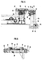
- FIG. 3 A system suitable for practicing the method according to the invention is shown in FIG. 3 and consists of an extrusion or tube press 1 and an outlet 2 for the extruded extrudates.
- the extruder 1 shown consists of a cylinder spar 3 with a press cylinder, the barrel 4, which is moved by a plunger and carries the press ram 5, a sensor 6 for the metal block to be pressed and a counter spar 7 supporting the die, which is connected to the die by tie rods 8 Cylinder beam 3 is connected.
- the outlet 2 consists of an outlet table 11 arranged in the longitudinal axis of the press 1, over which a pull-out carriage 12 can be moved.
- the pressed and extracted profiles are conveyed across the cooling bed 13 by means of rakes to a collecting table 14, from where they are conveyed longitudinally by a roller table 15 against a stop 16, by a dividing device (scissors or saw) 17 divided into commercial lengths and onto a collecting device 18 to be promoted across the board.
- the pull-out carriage 12 is moved along a rail 20 resting on supports 19.
- the frame 21 of the pull-out carriage 12, which is open at the bottom in the region of the rail 20, is provided on both ends with bearing blocks for the wheels 22 which guide the pull-out carriage 12 along the rail 20.
- the pull-out carriage 12 With a boom 23, the pull-out carriage 12 is guided on a further rail 24 by means of the wheels 25 mounted on the boom 23.
- a gripper 27 is guided on rods 26 in the pull-out direction.
- the gripper 27 consists of a two-part base plate 28, the halves of which can be swung out laterally, so that the gripper 27 can be opened downwards.
- slats 30 which can be pivoted about an axis 29 are provided, between which and the base plate 28 the profiles to be pulled out can be gripped by the gripper 27.
- the gripper 27 is intercepted relative to the frame 21 of the pull-out carriage 12 by means of pressure transducers 31 in the pull-out direction, so that the tensile force exerted by the gripper 27 on the profile to be pulled out is measured via the pressure transducers 31.
- a piston-cylinder unit 32 is provided in order to be able to pivot out the lamellae 30 in order to release the strand.
- the pull-out carriage 12 is moved along the rails 20 and 24 via a cable pull, consisting of a pull cable 33 and a capstan or a winch 34, which is driven by a speed and torque-controllable DC motor 35.
- the connection of the pull cable 33 to the pull-out carriage 12 takes place via a pull measuring device 36 which measures the pulling force exerted on the gripper 27 and exerted on the strand and the driving resistance of the pull-out carriage 12.
- the tensile force measured by the tension measuring device 36 minus the The tensile force exerted on the strand by the gripper 27 and measured by the pressure load cells 31 thus results in the driving resistance of the pull-out carriage 12.
- the pull-out carriage 12 is in standby immediately behind the counter beam 7 of the press 1. As soon as the tip of the strand reaches the area of the pull-out carriage 12 with its gripper 27, the pull-out carriage 12 is accelerated until it synchronizes with the strand.
- the resulting driving resistance of the pull-out carriage 12 is determined as a partial force (first summand) of a tractive force to be exerted by the traction drive (motor 35, capstan or winch 34) from the pull rope 33 (see diagram in FIG. 1).
- the gripper 27 closes by lifting the piston-cylinder unit 32 so that the slats 30 lower onto the base plate 28 and thus pinch the strand tip.
- the unit length of the strand corresponds, taking into account the specific weight of its material, to a cross-section, from which in turn the force with which the strand can be pulled out without the risk of a cross-sectional constriction, that is to say without influencing the shape in the die, depends.
- This partial force forms the second summand of the tensile force to be applied in the pull rope 33.
- the length of the extruded strand is continuously measured by pulse counting on a pulse generator 38 connected to the deflection roller 37 for the pulling rope 33 and multiplied by the specific profile friction force between the strand and the outlet table as the third partial value (third summand) of the tractive force to be applied, which increases proportionally with the strand length Pull rope 33 applied.
- the on Gripper 27 measured by the load cells 30 towing force and simultaneously the length of the tow tow.
- the towing force divided by the strand length corresponds to the actual value of the specific profile friction force and is specified for the following work cycle when pressing out the same strand cross section to determine the third summand of the tensile force.
- a torque measurement on the winch or the capstan 34, or connected with a speed measurement a measurement of the power consumption on the motor 35 can be provided to determine the pulling force in the pull rope 33 and the pulling force in the pull rope 33 can be determined therefrom.
- the driving resistance of the pull-out carriage 12 does not change in normal operation, it can be deducted as a constant from the force determined in the pull rope 33 in order to determine the summands 2 (pull-off force) and 3 (towing force), so that the load cell 31 and the In the pull-out direction, there is no need to fasten the gripper 27 in the pull-out carriage 12, and the constructional effort of the pull-out device can thus be reduced.
- the driving resistance is specified or entered as the 1st summand as the tractive force measured in the pull rope 33 when the pull-out carriage 12 is synchronized with the running strand before the gripper 27 closes. This is combined with the 2nd addend, with which the profile-specific, cross-section-dependent, empirically determined pull-off force is specified.
- the 3rd summand is the product of the respective length of the strand determined by displacement measurement by means of the pulse generator 38 and the specific profile friction force, which is determined empirically and predetermined for the first pressing process and for the following pressing process by measurement of the towing of the extruded strand after its separation from the baling residue and exit from the die required tensile force divided by the also measured length of this strand is determined and entered.
- the resulting 3rd summand is merged with the sum of the 1st and 2nd summands and results in the respective target value of the tensile force and from the comparison with the respective actual value of the tensile force the motor for driving the pull-out devices is regulated in its torque.
Landscapes
- Engineering & Computer Science (AREA)
- Mechanical Engineering (AREA)
- Extrusion Of Metal (AREA)
- Rigid Pipes And Flexible Pipes (AREA)
- Ropes Or Cables (AREA)
- Electric Cable Installation (AREA)
- Extrusion Moulding Of Plastics Or The Like (AREA)
- Metal Extraction Processes (AREA)
Claims (8)
- Procédé pour extraire une barre produite dans une presse à filer à barres ou à tubes, avec une force de traction asservie, qui maintient la barre tendue et qui n'influence pas la formation de la barre dans la filière,
caractérisé
en ce qu'on superpose à une force de traction (force de tirage) adaptée à la section et au comportement d'écoulement dans la filière, une force de traction (force de traînage) qui croît proportionnellement à la longueur de la barre filée et dans laquelle le poids par unité de longueur de la barre et le coefficient de frottement entre la barre et la table de réception (11) interviennent comme facteurs de multiplication appliqués à la valeur de la longueur instantanée de la barre. - Procédé selon la revendication 1,
caractérisé
en ce qu'après avoir coupé une barre et l'avoir extraite de la filière, on mesure la force de traînage et la longueur de la barre sortante et, pour l'extraction d'une barre suivante de même section de consigne, on prend la force de traînage divisée par la longueur de la barre comme valeur prévue de la force de frottement spécifique du profilé, qui doit être multipliée par la longueur de la barre, elle-même déterminée par une mesure de distance. - Commande pour le maintien de la constance de la force qui agit dans la région de la filière sur la barre sortant d'une presse à filer à barres ou à tubes,
caractérisée
en ce que, pour servir de valeur de consigne de la force de traction exercée sur la pointe de la barre, qui s'ajoutera à une valeur prédéterminée prenant en compte la résistance d'avance du chariot (12) du dispositif de tirage, et prise comme premier terme de la somme, et à une valeur de base de la force de tirage dépendant de la section de la barre et prise comme deuxième terme de la somme, on calcule et on introduit une valeur croissante, prise comme troisième terme de la somme, qui croît à partir de la saisie de la pointe de la barre par les pinces (27) du dispositif de tirage et qui est le produit instantané du résultat de la mesure continue de la longueur de sortie (38) et d'une force de frottement prédéterminée, spécifique du profilé, qui s'exerce entre la barre sortante et la table de réception (11). - Commande selon la revendication 3,
caractérisée
en ce qu'en prenant pour base la force de traînage, qui est mesurée après avoir coupé une barre et l'avoir extraite de la filière et prise comme valeur réelle, compte tenu de la longueur de la barre, on calcule un coefficient de correction qui donne la valeur de la force de frottement spécifique du profilé et on introduit ce coefficient. - Commande selon la revendication 3 ou 4,
caractérisée
en ce qu'on mesure et qu'on introduit comme premier terme de la somme la force nécessaire pour faire simplement avancer le chariot d'extraction (12) avant la saisie de la barre. - Commande selon la revendication 3 ou 4,
caractérisée
en ce qu'on mesure la force développée dans le câble (33) qui tire le chariot d'extraction (12) et la force développée au niveau de la pince (27) et qu'on introduit la différence entre ces forces comme premier terme de la somme (résistance d'avance). - Commande selon une des revendications précédentes,
caractérisée
en ce qu'il est prévu dans la région de la contre-filière (7) de la oresse (19), un dispositif qui signale l'apparition d'écarts par rapport à la rectitude et l'absence de méandres, de la sortie de la barre, c'est-à-dire la chute à zéro du deuxième terme de la somme de la force de traction, ce dispositif commandant la limite inférieure de la force de traction. - Commande selon une des revendications précédentes,
caractérisée
en ce que la valeur de consigne sert de grandeur réglante, après comparaison avec la valeur réelle de la force de traction mesurée au niveau du dispositif de tirage, et le couple d'un moteur à courant continu (35) qui entraîne un treuil à câble (34) agissant sur le dispositif de tirage composé du chariot (12) et de la pince (27) est réglé en fonction de cette grandeur.
Priority Applications (1)
| Application Number | Priority Date | Filing Date | Title |
|---|---|---|---|
| AT88110678T ATE74803T1 (de) | 1987-07-18 | 1988-07-05 | Verfahren zum abziehen eines in einer strangoder rohrpresse erzeugten stranges, sowie steuerung einer abziehvorrichtung hierzu. |
Applications Claiming Priority (2)
| Application Number | Priority Date | Filing Date | Title |
|---|---|---|---|
| DE19873723824 DE3723824A1 (de) | 1987-07-18 | 1987-07-18 | Verfahren zum abziehen eines in einer strang- oder rohrpresse erzeugten stranges, sowie steuerung einer abziehvorrichtung hierzu |
| DE3723824 | 1987-07-18 |
Publications (2)
| Publication Number | Publication Date |
|---|---|
| EP0300262A1 EP0300262A1 (fr) | 1989-01-25 |
| EP0300262B1 true EP0300262B1 (fr) | 1992-04-15 |
Family
ID=6331870
Family Applications (1)
| Application Number | Title | Priority Date | Filing Date |
|---|---|---|---|
| EP88110678A Expired - Lifetime EP0300262B1 (fr) | 1987-07-18 | 1988-07-05 | Procédé d'extraction du produit d'une presse d'extrusion de barres ou de tubes, ainsi que système de commande pour un dispositif d'extraction à cet effet |
Country Status (7)
| Country | Link |
|---|---|
| US (1) | US4995253A (fr) |
| EP (1) | EP0300262B1 (fr) |
| JP (1) | JPS6431521A (fr) |
| AT (1) | ATE74803T1 (fr) |
| DE (2) | DE3723824A1 (fr) |
| NO (1) | NO883135L (fr) |
| WO (1) | WO1993013885A1 (fr) |
Cited By (2)
| Publication number | Priority date | Publication date | Assignee | Title |
|---|---|---|---|---|
| DE10210475A1 (de) * | 2002-03-11 | 2003-10-02 | Sms Eumuco Gmbh | Vorrichtung zum Abziehen eines in einer Strang- oder Rohrpresse erzeugten Strangs |
| DE102012218223B4 (de) | 2012-10-05 | 2018-11-29 | Unterschütz Sondermaschinenbau GmbH | Abzugsvorrichtung für Strangpressanlagen zum Abziehen von Profilen aus einer Strangpressanlage |
Families Citing this family (3)
| Publication number | Priority date | Publication date | Assignee | Title |
|---|---|---|---|---|
| CA2016788C (fr) * | 1989-11-16 | 2000-03-21 | James T. Visser | Montage de pultrusion |
| EP0759331B1 (fr) * | 1995-08-12 | 1997-04-09 | SMS HASENCLEVER GmbH | Dispositif de transport transversal pas à pas de profilés entre une presse à extruder et une presseuse à tension |
| JP4102416B2 (ja) | 2006-11-15 | 2008-06-18 | 丸石製薬株式会社 | ゲル状殺菌消毒用組成物 |
Family Cites Families (9)
| Publication number | Priority date | Publication date | Assignee | Title |
|---|---|---|---|---|
| DE484649C (de) * | 1925-08-01 | 1931-08-03 | Kreidler Dipl Ing Alfred | Strang- bzw. Rohrpresse mit Abziehvorrichtung |
| DE878626C (de) * | 1951-05-01 | 1953-06-05 | Adolf Kreuser G M B H | Transportvorrichtung fuer auf Strangpressen hergestellte Rohre und Profile |
| US3001764A (en) * | 1957-01-22 | 1961-09-26 | Loewy Eng Co Ltd | Pull-out devices for metal extrusion presses with tension control |
| US3184788A (en) * | 1963-02-05 | 1965-05-25 | Edwin A Serrano | Extrusion control system |
| DE1602360C3 (de) * | 1967-02-15 | 1976-01-02 | Schloemann-Siemag Ag, 4000 Duesseldorf | Einrichtung zum Steuern einer Abziehvorrichtung für den aus einer Strangpresse austretenden Strang |
| DE2933262A1 (de) * | 1979-08-16 | 1981-02-26 | Elhaus Friedrich W | Ausziehvorrichtung fuer strangpressprofile |
| DE3404807A1 (de) * | 1984-02-10 | 1985-08-29 | Friedrich Wilhelm Dipl.-Ing. 7761 Moos Elhaus | Einrichtung zum regeln einer ausziehvorrichtung |
| GB2165476A (en) * | 1984-10-11 | 1986-04-16 | Bicc Plc | Extrusion of metals |
| JPS61180611A (ja) * | 1985-02-05 | 1986-08-13 | Fujisash Co | アルミニウム押出形材用プラ−装置 |
-
1987
- 1987-07-18 DE DE19873723824 patent/DE3723824A1/de not_active Withdrawn
-
1988
- 1988-07-05 DE DE8888110678T patent/DE3870068D1/de not_active Expired - Lifetime
- 1988-07-05 AT AT88110678T patent/ATE74803T1/de not_active IP Right Cessation
- 1988-07-05 EP EP88110678A patent/EP0300262B1/fr not_active Expired - Lifetime
- 1988-07-13 JP JP63172825A patent/JPS6431521A/ja active Granted
- 1988-07-14 NO NO88883135A patent/NO883135L/no unknown
- 1988-07-18 WO PCT/DE1988/000439 patent/WO1993013885A1/fr unknown
- 1988-07-18 US US07/327,809 patent/US4995253A/en not_active Expired - Fee Related
Cited By (3)
| Publication number | Priority date | Publication date | Assignee | Title |
|---|---|---|---|---|
| DE10210475A1 (de) * | 2002-03-11 | 2003-10-02 | Sms Eumuco Gmbh | Vorrichtung zum Abziehen eines in einer Strang- oder Rohrpresse erzeugten Strangs |
| DE10210475B4 (de) * | 2002-03-11 | 2004-05-06 | Sms Eumuco Gmbh | Vorrichtung zum Abziehen eines in einer Strang- oder Rohrpresse erzeugten Strangs |
| DE102012218223B4 (de) | 2012-10-05 | 2018-11-29 | Unterschütz Sondermaschinenbau GmbH | Abzugsvorrichtung für Strangpressanlagen zum Abziehen von Profilen aus einer Strangpressanlage |
Also Published As
| Publication number | Publication date |
|---|---|
| DE3723824A1 (de) | 1989-01-26 |
| JPS6431521A (en) | 1989-02-01 |
| WO1993013885A1 (fr) | 1993-07-22 |
| NO883135L (no) | 1989-01-19 |
| US4995253A (en) | 1991-02-26 |
| NO883135D0 (no) | 1988-07-14 |
| DE3870068D1 (de) | 1992-05-21 |
| JPH0323244B2 (fr) | 1991-03-28 |
| EP0300262A1 (fr) | 1989-01-25 |
| ATE74803T1 (de) | 1992-05-15 |
Similar Documents
| Publication | Publication Date | Title |
|---|---|---|
| DE921502C (de) | Verfahren und Walzwerk zur Herstellung von Metallband | |
| DE69928559T2 (de) | Verfahren zum wickeln von band | |
| DE2644298A1 (de) | Vorrichtung zum anschliessen einer bobine aus papier oder einem anderen material an eine andere bobine | |
| DE4442483A1 (de) | Verfahren und Vorrichtung zum Einbringen von Spannstählen in ein gemeinsames Rohr | |
| EP0300262B1 (fr) | Procédé d'extraction du produit d'une presse d'extrusion de barres ou de tubes, ainsi que système de commande pour un dispositif d'extraction à cet effet | |
| EP1837297B1 (fr) | Dispositif de réglage du décalage latéral de bandes | |
| DE10240718B4 (de) | Verfahren und Vorrichtung zum Abziehen von Extrusionsprodukten | |
| DE2623638C3 (de) | Vorrichtung zum Zuführen einer vulkanisierbaren Kautschukbahn zu einer Reifenaufbautrommel | |
| DE19544383C1 (de) | Verfahren und Vorrichtung zum Geradeausziehen und Einfädeln langen Ziehgutes in mehreren Schritten | |
| EP0325306A2 (fr) | Dispositif pour couper et attacher une bande de métal à une bobine | |
| DE102007005435B4 (de) | Verfahren und Vorrichtung zur Erzeugung eines zu einem Coil wickelbaren Metallbandes | |
| EP1514617A1 (fr) | Dispositif de tréfilage et méthode d'utilisation d'un dispositif de tréfilage | |
| DE60219924T2 (de) | Biegemaschine für profile und entsprechendes biegeverfahren | |
| DE3404807C2 (fr) | ||
| EP0153495B1 (fr) | Procédé d'étirage d'un tuyau métallique sans soudure | |
| DE102010007659A1 (de) | Stranggießmaschine mit einem Kaltstrang | |
| DE19708886C1 (de) | Verfahren und Vorrichtung zum kontinuierlichen Abziehen eines Schmelzefilms aus einer Folienproduktionsanlage | |
| DE3316161C2 (de) | Ausziehvorrichtung für die aus einer Strangpresse austretenden Profile | |
| AT394324B (de) | Verfahren und anlage zum entzundern von rundstahlstaeben | |
| EP1669141B1 (fr) | Procédé pour le réglage de la section des fils sortant d'un train de laminage de fil et train de laminage de fil | |
| EP0972592B2 (fr) | Procédé dispositif de coulée continue horizontale pour la fabrication des bandes métaliques enroulables | |
| EP0659494B1 (fr) | Procédé et dispositif pour emmener les tubes laminés à froid après un laminoir à pas de pèlerin froid | |
| DE2830333B1 (de) | Vorrichtung zum Iagerichtigen Transport von Bandanfaengen laengsgeteilter Metallbaender | |
| DE3040236A1 (de) | Anordnung zum ausziehen von strangpressprofilen | |
| DE102016110897A1 (de) | Spinnereivorbereitungsmaschine in Form einer Strecke sowie Verfahren zum Betreiben einer solchen |
Legal Events
| Date | Code | Title | Description |
|---|---|---|---|
| PUAI | Public reference made under article 153(3) epc to a published international application that has entered the european phase |
Free format text: ORIGINAL CODE: 0009012 |
|
| 17P | Request for examination filed |
Effective date: 19880709 |
|
| AK | Designated contracting states |
Kind code of ref document: A1 Designated state(s): AT BE CH DE ES FR GB IT LI NL SE |
|
| RAP1 | Party data changed (applicant data changed or rights of an application transferred) |
Owner name: SMS HASENCLEVER GMBH |
|
| 17Q | First examination report despatched |
Effective date: 19901023 |
|
| ITF | It: translation for a ep patent filed |
Owner name: DE DOMINICIS & MAYER S.R.L. |
|
| GRAA | (expected) grant |
Free format text: ORIGINAL CODE: 0009210 |
|
| AK | Designated contracting states |
Kind code of ref document: B1 Designated state(s): AT BE CH DE ES FR GB IT LI NL SE |
|
| PG25 | Lapsed in a contracting state [announced via postgrant information from national office to epo] |
Ref country code: SE Effective date: 19920415 Ref country code: NL Effective date: 19920415 Ref country code: ES Free format text: THE PATENT HAS BEEN ANNULLED BY A DECISION OF A NATIONAL AUTHORITY Effective date: 19920415 |
|
| REF | Corresponds to: |
Ref document number: 74803 Country of ref document: AT Date of ref document: 19920515 Kind code of ref document: T |
|
| REF | Corresponds to: |
Ref document number: 3870068 Country of ref document: DE Date of ref document: 19920521 |
|
| GBT | Gb: translation of ep patent filed (gb section 77(6)(a)/1977) | ||
| ET | Fr: translation filed | ||
| NLV1 | Nl: lapsed or annulled due to failure to fulfill the requirements of art. 29p and 29m of the patents act | ||
| PLBE | No opposition filed within time limit |
Free format text: ORIGINAL CODE: 0009261 |
|
| STAA | Information on the status of an ep patent application or granted ep patent |
Free format text: STATUS: NO OPPOSITION FILED WITHIN TIME LIMIT |
|
| 26N | No opposition filed | ||
| PGFP | Annual fee paid to national office [announced via postgrant information from national office to epo] |
Ref country code: AT Payment date: 19940628 Year of fee payment: 7 |
|
| PGFP | Annual fee paid to national office [announced via postgrant information from national office to epo] |
Ref country code: BE Payment date: 19940713 Year of fee payment: 7 |
|
| PGFP | Annual fee paid to national office [announced via postgrant information from national office to epo] |
Ref country code: CH Payment date: 19941029 Year of fee payment: 7 |
|
| PGFP | Annual fee paid to national office [announced via postgrant information from national office to epo] |
Ref country code: FR Payment date: 19950623 Year of fee payment: 8 |
|
| PGFP | Annual fee paid to national office [announced via postgrant information from national office to epo] |
Ref country code: GB Payment date: 19950626 Year of fee payment: 8 Ref country code: DE Payment date: 19950626 Year of fee payment: 8 |
|
| PG25 | Lapsed in a contracting state [announced via postgrant information from national office to epo] |
Ref country code: AT Effective date: 19950705 |
|
| PG25 | Lapsed in a contracting state [announced via postgrant information from national office to epo] |
Ref country code: LI Effective date: 19950731 Ref country code: CH Effective date: 19950731 Ref country code: BE Effective date: 19950731 |
|
| BERE | Be: lapsed |
Owner name: SMS HASENCLEVER G.M.B.H. Effective date: 19950731 |
|
| REG | Reference to a national code |
Ref country code: CH Ref legal event code: PL |
|
| PG25 | Lapsed in a contracting state [announced via postgrant information from national office to epo] |
Ref country code: GB Effective date: 19960705 |
|
| GBPC | Gb: european patent ceased through non-payment of renewal fee |
Effective date: 19960705 |
|
| PG25 | Lapsed in a contracting state [announced via postgrant information from national office to epo] |
Ref country code: FR Effective date: 19970328 |
|
| PG25 | Lapsed in a contracting state [announced via postgrant information from national office to epo] |
Ref country code: DE Effective date: 19970402 |
|
| REG | Reference to a national code |
Ref country code: FR Ref legal event code: ST |
|
| PG25 | Lapsed in a contracting state [announced via postgrant information from national office to epo] |
Ref country code: IT Free format text: LAPSE BECAUSE OF NON-PAYMENT OF DUE FEES;WARNING: LAPSES OF ITALIAN PATENTS WITH EFFECTIVE DATE BEFORE 2007 MAY HAVE OCCURRED AT ANY TIME BEFORE 2007. THE CORRECT EFFECTIVE DATE MAY BE DIFFERENT FROM THE ONE RECORDED. Effective date: 20050705 |