EP0292989B1 - Apparatus and method for effecting fine movement by impact force produced by piezoelectric or electrostrictive element - Google Patents
Apparatus and method for effecting fine movement by impact force produced by piezoelectric or electrostrictive element Download PDFInfo
- Publication number
- EP0292989B1 EP0292989B1 EP88108499A EP88108499A EP0292989B1 EP 0292989 B1 EP0292989 B1 EP 0292989B1 EP 88108499 A EP88108499 A EP 88108499A EP 88108499 A EP88108499 A EP 88108499A EP 0292989 B1 EP0292989 B1 EP 0292989B1
- Authority
- EP
- European Patent Office
- Prior art keywords
- piezoelectric
- electrostrictive element
- moving member
- driving
- effecting
- Prior art date
- Legal status (The legal status is an assumption and is not a legal conclusion. Google has not performed a legal analysis and makes no representation as to the accuracy of the status listed.)
- Revoked
Links
Images


Classifications
-
- H—ELECTRICITY
- H02—GENERATION; CONVERSION OR DISTRIBUTION OF ELECTRIC POWER
- H02N—ELECTRIC MACHINES NOT OTHERWISE PROVIDED FOR
- H02N2/00—Electric machines in general using piezoelectric effect, electrostriction or magnetostriction
-
- H—ELECTRICITY
- H02—GENERATION; CONVERSION OR DISTRIBUTION OF ELECTRIC POWER
- H02N—ELECTRIC MACHINES NOT OTHERWISE PROVIDED FOR
- H02N2/00—Electric machines in general using piezoelectric effect, electrostriction or magnetostriction
- H02N2/0095—Electric machines in general using piezoelectric effect, electrostriction or magnetostriction producing combined linear and rotary motion, e.g. multi-direction positioners
-
- H—ELECTRICITY
- H02—GENERATION; CONVERSION OR DISTRIBUTION OF ELECTRIC POWER
- H02N—ELECTRIC MACHINES NOT OTHERWISE PROVIDED FOR
- H02N2/00—Electric machines in general using piezoelectric effect, electrostriction or magnetostriction
- H02N2/02—Electric machines in general using piezoelectric effect, electrostriction or magnetostriction producing linear motion, e.g. actuators; Linear positioners ; Linear motors
- H02N2/021—Electric machines in general using piezoelectric effect, electrostriction or magnetostriction producing linear motion, e.g. actuators; Linear positioners ; Linear motors using intermittent driving, e.g. step motors, piezoleg motors
- H02N2/025—Inertial sliding motors
-
- H—ELECTRICITY
- H02—GENERATION; CONVERSION OR DISTRIBUTION OF ELECTRIC POWER
- H02N—ELECTRIC MACHINES NOT OTHERWISE PROVIDED FOR
- H02N2/00—Electric machines in general using piezoelectric effect, electrostriction or magnetostriction
- H02N2/02—Electric machines in general using piezoelectric effect, electrostriction or magnetostriction producing linear motion, e.g. actuators; Linear positioners ; Linear motors
- H02N2/06—Drive circuits; Control arrangements or methods
- H02N2/065—Large signal circuits, e.g. final stages
- H02N2/067—Large signal circuits, e.g. final stages generating drive pulses
Definitions
- the present invention relates to an apparatus and method for effecting a fine movement of an object by making use of impact produced by piezoelectric/electrostrictive element.
- Fig. 1 and 2 illustrate known apparatus for effecting a fine movement of an object by a mechanical means.
- a moving member 1 having a mass M is provided with an electromagnetic device.
- a coil 3 as an inertia member is supported on the moving member through a buffer member 2 such as a spring.
- the electromagnetic device produces an electromagnetic impacting force which is caused by repulsion and collision of the coil 3, thereby effecting fine movement of the moving member.
- a moving member 5 incorporates an electromagnetic device capable of imparting an impact to the moving member 5.
- the moving member 5 has legs constituted by a permanent magnet so that the moving member 5 is moved by a small amount by impacting force produced by the electromagnetic device, while being attracted to the surface of a base on which a groove 8 is formed.
- the moving apparatus relying upon impacting electromagnetic force essentially requires a circuit which generates a magnetic field by means of a coil.
- the coil has to have certain volume and surface area in order to attain a high efficiency while avoiding generation of heat, magnetic field or electromagnetic noise.
- both types of known apparatus mentioned above suffer from a common disadvantage in that noise and dust tend to be generated due to collision of the inertia member.
- an object of the present invention is to provide a compact and highly efficient apparatus for effecting a fine movement by an impacting force which is produced by a piezoelectric/electrostrictive element capable of performing a noise-less driving without generating any magnetic field and electromagnetic noise.
- a method for effecting a fine movement according to the invention is characterized in claims 9 and 10.
- the apparatus of the present invention for effecting fine movement employs different driving methods which rely upon different types of constructions. These driving methods will be described first in advance of the description of the respective embodiments.
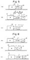
- a moving member 12 is fixed to one end of a piezoelectric/electrostrictive element 11 capable of generating impact force.
- An inertia member 13 is fixed to the other end of the piezoelectric/electrostrictive element 11.
- a numeral 14 designates a base having a friction surface 14a.
- the movement in small amount can be effected by following a procedure which is reverse to the cycle described above.
- the maximum distance of travel is limited by the upper limit of the acceleration imparted to the inertia member 13,and is represented by m ⁇ l/(M+m) . If the moving member 12 is clamped electrostatically or electromagnetically within the period of said Step (1) above, the acceleration of the inertia member 13 is increased to attain a greater amount of movement.
- Fine movement according to a method 1-B′ is effected by reversing the operation cycle according to the method 1-B.
- Figs. 9(a) to 9(c) are time charts showing an example of operation of the piezoelectric/electrostrictive element in one cycle of operation in which the driving methods 1-A and 1-B explained before are combined. More specifically, Figs. 9(a), 9(b) and 9(c) represent, respectively, the voltage V applied to the piezoelectric/electrostrictive element 11, the elongation l ( ⁇ m) of the piezoelectric/electrostrictive element, and the displacement l ( ⁇ m) of the moving member.
- a voltage V of 150V when a voltage V of 150V is abruptly applied to the piezoelectric/electrostrictive element at a moment t1, the piezoelectric/electrostrictive element exhibits an elongation of about 16 ⁇ m at a moment t2 after elapse of 50 ⁇ s from the moment t1, as shown in Fig. 9(b).
- the moving member travels a distance of about 3 ⁇ m, as shown in Fig. 9(c).
- the piezoelectric/electrostrictive element is reset while being progressively accelerated past a moment t3 (about 2 ms after) to a moment t4 (about 4 ms after). After the moment t4, the moving member further moves.
- Fig. 10 is a time chart illustrating the operation in accordance with the driving methods 1-A′ and 1-B′.
- Figs. 10(a) to 10(c) are time charts showing an example of operation of the piezoelectric/electrostrictive element in one cycle of operation in which the driving methods 1-A′ and 1-B′ explained before are combined. More specifically, Figs. 10(a), 10(b) and 10(c) represent, respectively, the voltage V applied to the piezoelectric/electrostrictive element 11, the elongation l ( ⁇ m) of the piezoelectric/electrostrictive element, and the displacement l ( ⁇ m) of the moving member. In this case, the piezoelectric/electrostrictive element is driven in the direction counter to the direction of driving attained in the operation shown in Fig. 9.
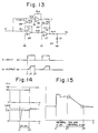
- Fig. 11 is a schematic block diagram of the driving system for driving the piezoelectric/electrostrictive element
- Fig. 12 is a circuit diagram illustrating an example of the driving amplifier used in the system
- Fig. 13 is an illustration of an example of an analog circuit for generating waveform to be input to the driving amplifier.
- a digital signal output from the microcomputer 15 is converted into an analog signal by the D/A converter 16 and is input to the driving amplifier 17, and the output from the driving amplifier 17 is input to the piezoelectric/electrostrictive element 18.
- a keyboard/display unit 19 is connected to the microcomputer 15 so as to enable input of data for generating waveform, as well as monitoring of the waveform. It is thus possible to input various voltage waveforms as shown in Figs. 9 and 10 into the driving amplifier 17.
- the piezoelectric/electrostrictive element 18 is electrically equivalent to a capacitor and has a comparatively large capacitance of, for example, about 5 ⁇ F.
- a high voltage e.g. 150V
- a high speed e.g., a settling time of 50 ⁇ s as shown in Figs. 9 and 10
- the final stage of the driving amplifier is constituted by an amplifier unit of a high voltage and low output impedance.
- R1 to R10 represent resistors
- 20,21 represent amplifiers
- 22, 23 and 24 represent transistors.
- the resistors R7 and R8 have resistance values of 10 ⁇
- R9 has a resistance value of 90 K ⁇
- R10 has a resistance value of 10 K ⁇ .
- the circuit arrangement may be,for example, as shown in Fig. 13.
- the circuit has resistors R11 to R17, capacitors C1, C2, a diode D1, a P-channel FET (depletion type) 28, an N-channel FET (depletion type) 29,and a D.C. power supply 30 for setting the amplitude of the output.
- Symbols V i and V0 respectively represent the input waveform and an output waveform which are applicable to the driving method 1-A′ or 1-B′ explained before.
- the portion of the output waveform V0 in the period between a moment t1 and a moment t2 constitute a parabolic curve constituted by a first integration circuit including the resistor R11 and the capacitor C1 and a second integration circuit constituted by the resistor R15 and the capacitor C2.
- the FETs 28 and 29 become conductive so that the capacitors C1 and C2 discharge.
- the operation cycle composed of the methods 1-A and 1-B or the operation cycle composed of the methods 1-A′ and 1-B′ are repeated.
- each cycle has a period of several to ten and several milliseconds, and the travel per each operation cycle is several ⁇ m.
- the cycle therefore is repeated to cause a movement at a speed of about 0.1 mm/s to 1 mm/s.
- the following method for example, which is different from the method for effecting a long-distance travel explained above. More specifically, the method is similar to the driving method 1-A and 1-A′ explained before.
- the moving member has to be located with a precision on the order of 1 ⁇ m. It is also assumed that, although an attempt was made to effect the 1 ⁇ m travel by applying a voltage of 50 V to the piezoelectric/electrostrictive element at a moment t1 as shown in Fig. 14, the moving member actually moved only 0.9 ⁇ m due to a disturbance. This shortage of the travel distance is detected by a sensor and, in order to effect the travel over the remaining 0.1 ⁇ m, the applied voltage is increased by 5V in a stepped manner at the moment t2. Thus, the applied voltage is increased to 55 V.
- the piezoelectric/electrostrictive element is further expanded in a stepped manner similarly to the method 1-A or contracted similarly to 1-A′, rather than resetting the length of the piezoelectric/electrostrictive element gently to the original length.
- This fine adjustment is possible to a fact that, if the factors such as ⁇ , m and k have been selected to enable the influence of the friction to be neglected, the moving member travels a distance which is a function of the elongation ⁇ l, e.g., a certain proportion [m/(M+m)] of the elongation ⁇ l, regardless of the initial length of the piezoelectric/electrostrictive element.
- the fine position adjustment is commenced from a state in which the piezoelectric/electrostrictive element has been contracted. In some cases, it is quite unknown in which direction the fine movement is to be effected. In such cases, as shown in Fig. 15, the piezoelectric/electrostrictive element is maintained at a state in which it has been elongated by an amount which is half the maximum elongation, and then a high speed movement is effected to bring the object to the command position within several milli seconds.
- the piezoelectric/electrostrictive element is gently to the initial state, i.e., to the half elongation, in such a manner that the force of inertia acting on the inertia member does not exceed the static friction acting between the moving member and the base.
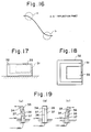
- the movement tends to occur when the inertia member is accelerated or decelerated. It is therefore necessary that the movement is effected with a constant acceleration as shown in Fig. 16. Namely, acceleration and deceleration are effected in such a manner as to follow the parabolic curve. At the same time, the acceleration is maintained below the level of ⁇ (M+m)g/m .
- the second embodiment employs a bimorph type piezoelectric/electrostrictive element 31, a moving member 32 to which the piezoelectric/electrostrictive element 31 is attached, and an inertia member 33 attached to the free end of the piezoelectric/electrostrictive element 31.
- An electrode 36 in the form of a foil is sandwiched between a pair of piezoelectric crystalline plates 34 and 35, and a voltage is applied between the electrode 36 and an external electrodes 37.
- one of the crystalline plates expands while the other contracts, so that the bimorf piezoelectric/electrostrictive element is bent in one direction. Since the moving member is attached to a base end of the piezoelectric/electrostrictive element while the inertia member is attached to the free end of the piezoelectric/electrostrictive element, the moving member is moved in response to an impact generated by the inertia member.
- the moving member is held on the base in a manner which will be explained hereinunder.
- the moving member is held on the base only by friction,so that the moving member is preferably clamped intentionally in the case where a strong external force is expected to be applied to the moving member.
- the clamping may be effected by,for example, a permanent magnet or an electromagnet. It is also possible to hold the moving member by electrostatic force.
- the two types of the known methods explained before may be employed. In the case of the present invention, however, the attracting force need not be so large.
- the inertia member When the inertia member has a large mass, the arrangements shown in Figs. 3 and 4 and Figs. 17 and 18 may be unsatisfactory from the view point of durability. In such a case, it is advisable that the inertia member is supported in a manner shown in Figs. 20 or 21.
- the inertia member 43 In the arrangement shown in Fig. 20, the inertia member 43 is attached through the piezoelectric/electrostrictive element 41 to a vertical portion 42a of the moving member 42 which has an L-shaped cross-section. At the same time,the inertia member 43 is supported on the bottom 42b of the moving member 42 through a bearing 44.
- the arrangement shown in Fig. 21 employs a plurality of leaf springs 48 which supports upper and lower ends of the inertia member 47 provided through the intermediary of the piezoelectric/electrostrictive element 45 of the moving member 46.
- Figs. 22(a) to 22(f) are plan views of an apparatus for effecting a fine movement, having an impact generating mechanisms each incorporating a piezoelectric/electrostrictive element. More specifically, impact generating mechanisms a-1 and a-2 are provided on the upper and lower portions of the left side of the moving member 50. Similarly, impact generating mechanisms c-2, c-1, b-1, b-2 and d-2, d-1 are secured to the upper and lower portions of the right side of the moving member 50, the left and right ends of the lower side of the moving member 50 and the left and right ends of the upper side of the moving member 50, respectively.
- Fig. 22(a) it is possible to drive the moving member 50 in the direction of +x, by driving the impact generating mechanisms a-1 and a-2 by the driving method 1-A or 1-B.
- the moving member 50 is driven in the direction of -x, by driving the impact generating mechanisms c-1, c-2.
- driving of the impact generating mechanisms b-1, b-2 causes the moving member 50 to move in the direction of +y as shown in Fig. 22(c)
- the driving of the impact generating mechanisms d-1, d-2 causes the moving member 50 to move in the direction of -y as shown in Fig. 22(d).
- the impact generating mechanisms a-1 and c-1 are driven to cause the moving member 50 to rotate clockwise as indicated by - ⁇ , whereas, in Fig. 22(f), the impact generating mechanisms a-2 and c-2 are driven to rotate the moving member 50 counter-clockwise as indicated by + ⁇ .
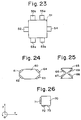
- Fig. 24 shows another arrangement in which impact generating mechanisms 61 to 64 are disposed on six sides of a hexagonally cross-sectioned elongated moving member 60
- Fig. 25 shows an arrangement in which impact generating mechanisms 66 to 69 are attached to the slant surfaces of a moving member 65 which has a varying circular cross-section and contracted at its axially mid portion.
- the impact generating mechanisms can be driven by the driving method 1-A or 1-B, i.e., in such a manner as to push the moving member.
- the driving in the +x direction is effected by the activation of the impact generating mechanisms 61 and 62, while the driving in the +y direction and in the + ⁇ direction are effected, respectively, by the operations of the impact generating mechanisms 62, 63 and 61, 63.
- the driving in the +x direction is caused by the operations of the impact generating mechanisms 66 and 67.
- the driving in the +y direction and in the + ⁇ direction are respectively caused by the impact generating mechanisms 66, 69 and the impact generating mechanisms 67, 69.
- Each impact generating mechanism can impart impact both in the positive and negative directions, so that the desired movement can be attained only by three impact generating mechanisms 71 to 73 provided on the moving member 70 as shown in Fig. 26. More specifically, the impact generating mechanism 71 is driven in accordance with the driving methods 1-A and 1-B so that the movement in the +x direction is attained. The movement in the +y direction is effected by driving the impact generating mechanisms 72 and 73 in accordance with the methods 1-A,1-B. The movement in the + ⁇ direction is attained by driving the impact generating mechanism 72 in accordance with the driving methods 1-A′, 1-B′, while driving the impact generating mechanism 73 in accordance with the driving methods 1-A,1-B.
- the movement in the -x direction is effected by driving the impact generating mechanism 71 in accordance with the driving methods 1-A′, 1-B′.
- the driving in the -y direction is caused by driving the impact generating mechanisms 72 and 73 in accordance with the driving methods 1-A′, 1-B′.
- the driving in the - ⁇ direction is caused by driving the impact generating mechanism 72 by the driving methods 1-A,1-B, while driving the impact generating mechanism 73 by the driving methods 1-A′,1-B′.
- the provision of the impact generating mechanism inside the moving member makes it easy to realize such an arrangement in which the piezoelectric/electrostrictive element is free from bending moment.
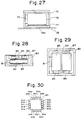
- Fig. 27 shows an example of the arrangement constructed from this point of view and designed to effect a uni-axial movement.
- this arrangement employs a moving member 74, a piezoelectric/electrostrictive element 75, an inertia member 76, a bearing 77, and a base 78 having a friction surface 78a.
- Figs. 28 and 29 show an example of the apparatus of the invention for effecting fine movement along three axes.
- This apparatus has a box-shaped moving member 80, piezoelectric/electrostrictive elements 81, 84, 86,inertia members 82, 85, 87 and bearings 83.
- the impact generating mechanism is loaded to be operative three-dimensionally.
- the moving member When the moving member is constructed by making use of a bimorph element, it takes a considerable time for the vibration of the spring to be ceased. It is,therefore, effective to provide units of impact generating mechanisms such as those denoted by 91a-91e, 92a-92e, 93a-93e and 94a-94e on the respective sides of the moving member 90 and to drive them in sequence as shown in Fig. 30.
- the piezoelectric/electrostrictive element used in the apparatus of the invention is made of,for example, a piezoelectric element such as quartz or Rochelle salt,and is mounted between a pair of electrodes 95 and 96 as shown in Fig. 31.
- a voltage is applied, for example, that the electrode 95 is set at plus (+), while the electrode 96 is set at minus (-) as shown in Fig. 31(a), so that the piezoelectric/electrostrictive element produce a force which tends to expand the piezoelectric/electrostrictive element (inverse piezoelectric effect).
- the magnitude of the force is substantially proportional to the level of the electric field,and the direction of the strain can be reversed by reversing the direction of the electric field as shown in Fig. 31(b). It is possible to obtain the strain in desired directions according to the orientation of cutting of crystals. For instance, the strain can appear in the same direction as the charges (longitudinal piezoelectric effect) or in the orthogonal direction to the direction of charges (transverse piezoelectric effect). It is also possible to attain the strain in the form of a slip of the material.
- the piezoelectric/electrostrictive element used in the apparatus of the present invention includes so-called electrostrictive elements which, when placed in the influence of an external electric field,produces a strain substantially proportional to the square of the intensity of the electric field.
- electrostrictive elements which, when placed in the influence of an external electric field,produces a strain substantially proportional to the square of the intensity of the electric field.
- strong dielectric materials such as ceramics of barium titanate system and ceramics of titanate-zirconate system.
- magnetostrictive element in place of the piezoelectric/electrostrictive element used in the embodiments.
- magnetostrictive alloys formed from iron and various rare earth elements such including terbium, samarium, holmium and dysprocium can have such a property as to expand very quickly and the amount of extension is large, according to the preparation methods of such alloys, so that they can conveniently be used in the apparatus of the invention for effecting fine movement.
- the present invention offers the following advantages.
Landscapes
- General Electrical Machinery Utilizing Piezoelectricity, Electrostriction Or Magnetostriction (AREA)
Applications Claiming Priority (2)
| Application Number | Priority Date | Filing Date | Title |
|---|---|---|---|
| JP62131304A JPS63299785A (ja) | 1987-05-29 | 1987-05-29 | 圧電・電歪素子を用いた衝撃力による微小移動装置 |
| JP131304/87 | 1987-05-29 |
Publications (3)
| Publication Number | Publication Date |
|---|---|
| EP0292989A2 EP0292989A2 (en) | 1988-11-30 |
| EP0292989A3 EP0292989A3 (en) | 1990-07-18 |
| EP0292989B1 true EP0292989B1 (en) | 1993-12-15 |
Family
ID=15054829
Family Applications (1)
| Application Number | Title | Priority Date | Filing Date |
|---|---|---|---|
| EP88108499A Revoked EP0292989B1 (en) | 1987-05-29 | 1988-05-27 | Apparatus and method for effecting fine movement by impact force produced by piezoelectric or electrostrictive element |
Country Status (5)
| Country | Link |
|---|---|
| US (1) | US4894579A (enExample) |
| EP (1) | EP0292989B1 (enExample) |
| JP (1) | JPS63299785A (enExample) |
| KR (1) | KR0132437B1 (enExample) |
| DE (1) | DE3886260T2 (enExample) |
Cited By (2)
| Publication number | Priority date | Publication date | Assignee | Title |
|---|---|---|---|---|
| US8004153B2 (en) | 2007-03-14 | 2011-08-23 | Cedrat Technologies | Fine positioning system using an inertial motor based on a mechanical amplifier |
| CN109905053A (zh) * | 2019-04-23 | 2019-06-18 | 苏州大学 | 一种双足式惯性粘滑驱动跨尺度精密运动平台 |
Families Citing this family (67)
| Publication number | Priority date | Publication date | Assignee | Title |
|---|---|---|---|---|
| US5317223A (en) * | 1987-01-21 | 1994-05-31 | Dynamotive Corporation | Method and device in magnetostrictive motion systems |
| US5049775A (en) * | 1988-09-30 | 1991-09-17 | Boston University | Integrated micromechanical piezoelectric motor |
| DE3933296C2 (de) * | 1988-12-28 | 1994-06-01 | Prima Meat Packers Ltd | Mikromanipulator |
| JPH0773830B2 (ja) * | 1989-04-06 | 1995-08-09 | プリマハム株式会社 | マイクロマニピュレータ |
| JPH03129312A (ja) * | 1989-07-18 | 1991-06-03 | Toshiro Higuchi | 光学実験等のための微動ステージ |
| JPH0389875A (ja) * | 1989-08-31 | 1991-04-15 | Brother Ind Ltd | リニア超音波モータ |
| JPH0648975B2 (ja) * | 1989-10-02 | 1994-06-29 | 俊郎 樋口 | 微小インジェクション装置及びそのインジェクション制御方法 |
| US5105117A (en) * | 1989-10-31 | 1992-04-14 | Brother Kogyo Kabushiki Kaisha | Ultrasonic motor |
| JPH0698584B2 (ja) * | 1989-11-24 | 1994-12-07 | 俊郎 樋口 | マイクロマニピュレータの微小移動装置 |
| JPH0430989A (ja) * | 1990-05-24 | 1992-02-03 | Fuji Electric Co Ltd | 位置決めアクチュエータ装置 |
| US5225941A (en) * | 1990-07-03 | 1993-07-06 | Canon Kabushiki Kaisha | Driving device |
| JP2797146B2 (ja) * | 1990-10-09 | 1998-09-17 | 株式会社ゼクセル | 物体移動用電磁アクチュエータ |
| US5490015A (en) * | 1993-03-04 | 1996-02-06 | Olympus Optical Co., Ltd. | Actuator apparatus |
| JPH06312384A (ja) * | 1993-04-27 | 1994-11-08 | Olympus Optical Co Ltd | 自走装置 |
| JP3269703B2 (ja) * | 1993-06-21 | 2002-04-02 | オリンパス光学工業株式会社 | 処置具の駆動機構 |
| US5589723A (en) * | 1994-03-29 | 1996-12-31 | Minolta Co., Ltd. | Driving apparatus using transducer |
| JPH0821946A (ja) * | 1994-07-08 | 1996-01-23 | Minolta Co Ltd | 電気−機械変換素子を使用したレンズ装置駆動機構 |
| US5587846A (en) * | 1994-07-15 | 1996-12-24 | Minolta Co., Ltd. | Lens moving apparatus |
| US5629577A (en) * | 1994-07-15 | 1997-05-13 | Micro Medical Devices | Miniature linear motion actuator |
| JPH0837784A (ja) * | 1994-07-25 | 1996-02-06 | Nikon Corp | 移動装置及び移動装置の制御方法 |
| JPH0843872A (ja) * | 1994-08-03 | 1996-02-16 | Minolta Co Ltd | 電気−機械変換素子を使用したレンズ駆動装置 |
| JPH0866064A (ja) * | 1994-08-24 | 1996-03-08 | Nikon Corp | 圧電アクチュエータ |
| US5668432A (en) * | 1995-03-24 | 1997-09-16 | Nippondenso Co., Ltd. | Articulation device |
| US5786654A (en) * | 1995-06-08 | 1998-07-28 | Minolta Co., Ltd. | Movable stage utilizing electromechanical transducer |
| US5600239A (en) * | 1995-06-16 | 1997-02-04 | The United States Of America As Represented By The Secretary Of The Navy | Strain sensing system including a magnetostrictive material having a piezomagnetic property selected for maximizing electrical impedance to current applied to a predetermined skin depth |
| US5675444A (en) * | 1995-07-27 | 1997-10-07 | Minolta Co., Ltd. | Lens barrel having a piezoelectric actuator for moving optical elements |
| JPH09191665A (ja) * | 1996-01-04 | 1997-07-22 | Minolta Co Ltd | 電気−機械変換素子を使用した直線駆動機構 |
| JP3358418B2 (ja) * | 1996-01-04 | 2002-12-16 | ミノルタ株式会社 | 電気−機械変換素子を使用した駆動機構 |
| DE19627927C2 (de) * | 1996-07-11 | 1999-10-14 | Egon Illig | Bewegungseinrichtung und Verfahren zur Bewegung |
| GB2316222B (en) * | 1996-08-05 | 1998-07-01 | Karrai Haines Gbr | Inertial positioner |
| US5986826A (en) * | 1996-12-17 | 1999-11-16 | Minolta Co., Ltd. | Drive device using electromechanical conversion element |
| US6051909A (en) * | 1996-12-27 | 2000-04-18 | Minolta Co., Ltd. | Drive device using electromechanical transducer |
| JP3184117B2 (ja) * | 1997-05-23 | 2001-07-09 | セイコーインスツルメンツ株式会社 | 超音波モータ及び超音波モータ付き電子機器 |
| JPH1144899A (ja) * | 1997-07-25 | 1999-02-16 | Minolta Co Ltd | 電気機械変換素子を使用した駆動装置 |
| DE19927129C1 (de) * | 1999-06-15 | 2001-01-04 | Wolf Gmbh Richard | Fokussier- und Brennweiteneinstellvorrichtung für eine Videokamera |
| US6251658B1 (en) | 1999-06-18 | 2001-06-26 | Burleigh Instruments, Inc | Inertial impact drill for cytological applications |
| DE10012751B4 (de) * | 2000-03-16 | 2004-05-27 | Carl Zeiss Jena Gmbh | Verstellvorrichtung zum Verschieben einzelner Elemente von optischen Systemen oder von Meßsystemen |
| US6774533B2 (en) * | 2000-03-17 | 2004-08-10 | Japan Science And Technology Agency | Electrostatic impact driving microactuator |
| KR100486702B1 (ko) * | 2000-07-25 | 2005-05-03 | 삼성전자주식회사 | 마이크로 로봇 |
| US6661575B1 (en) | 2000-10-31 | 2003-12-09 | Sergey A. Yakovenko | Methods and apparata for micromanipulation of micro-and nanoparticles |
| US6936951B1 (en) | 2000-11-27 | 2005-08-30 | Grq Instruments, Inc. | Smart sonic bearings and method for frictional force reduction and switching |
| SE520097C2 (sv) | 2000-12-05 | 2003-05-27 | Nanofactory Instruments Ab | Mikropositioneringsanordning |
| JP4537591B2 (ja) * | 2001-02-02 | 2010-09-01 | 株式会社ナノコントロール | 光軸合わせ装置および光軸合わせ方法 |
| US7131891B2 (en) * | 2003-04-28 | 2006-11-07 | Micron Technology, Inc. | Systems and methods for mechanical and/or chemical-mechanical polishing of microfeature workpieces |
| JP2006197216A (ja) * | 2005-01-13 | 2006-07-27 | Olympus Imaging Corp | ブレ補正機能付き撮影装置及びブレ補正方法 |
| DE102005026708B4 (de) | 2005-06-09 | 2007-05-03 | Attocube Systems Ag | Positionierer mit Festkörpergelenk |
| JP4652906B2 (ja) | 2005-06-30 | 2011-03-16 | 富士夫 宮脇 | 振動型マイクロインジェクション装置 |
| JP4907923B2 (ja) * | 2005-08-25 | 2012-04-04 | 公立大学法人首都大学東京 | 微小物品搬送装置 |
| US7180221B1 (en) | 2005-09-17 | 2007-02-20 | Felix Torres | Piezo-electric assembly |
| CN101606312B (zh) * | 2007-02-09 | 2012-08-08 | 柯尼卡美能达精密光学株式会社 | 驱动装置 |
| US8059346B2 (en) | 2007-03-19 | 2011-11-15 | New Scale Technologies | Linear drive systems and methods thereof |
| JP5305380B2 (ja) * | 2008-01-08 | 2013-10-02 | Necトーキン株式会社 | アクチュエータ、位置決め装置 |
| JP5341554B2 (ja) * | 2009-02-26 | 2013-11-13 | 太平洋セメント株式会社 | 位置決め制御ユニット、位置決め制御方法および位置決め制御プログラム |
| JP5490132B2 (ja) | 2009-11-04 | 2014-05-14 | 株式会社東芝 | 駆動装置 |
| WO2011055000A1 (en) * | 2009-11-06 | 2011-05-12 | Sensapex Oy | Compact micromanipulator |
| WO2011102365A1 (ja) * | 2010-02-16 | 2011-08-25 | パナソニック電工株式会社 | 駆動装置および該駆動装置を用いた移動機構 |
| US20130009492A1 (en) * | 2010-02-16 | 2013-01-10 | Sanyo Electric Co., Ltd. | Drive device, and movement mechanism using drive device |
| JP5269009B2 (ja) | 2010-07-30 | 2013-08-21 | 株式会社東芝 | 駆動装置 |
| EP2420187B1 (en) * | 2010-08-16 | 2013-02-13 | Precision Bioinstrument LLC | Individually adjustable multi-channel systems in vivo recording |
| JP2013020589A (ja) * | 2011-07-14 | 2013-01-31 | Sanyo Electric Co Ltd | 機器移動システム |
| DE102013204131B3 (de) | 2013-03-11 | 2014-02-06 | Bruker Biospin Ag | NMR-Probenkopf mit einem mittels eines piezoelektrischen Aktors diskret verstellbaren variablen Kondensator im HF-Schwingkreis |
| JP6406593B2 (ja) | 2013-12-28 | 2018-10-17 | 株式会社ミクロブ | 駆動機構 |
| DE102014109849A1 (de) | 2014-07-14 | 2016-01-14 | Piezosystem Jena Gmbh | Anordnung und Verfahren zum stoßwellengeführten Bewegen eines Objektes |
| IT201800003187A1 (it) * | 2018-03-01 | 2019-09-01 | Balance Systems Srl | Dispositivo di movimentazione di un oggetto, in particolare per un apparato di equilibratura |
| FR3092454B1 (fr) | 2019-02-04 | 2022-06-10 | Cedrat Tech | Mecanisme de deplacement nanometrique a vis |
| CN109905052B (zh) * | 2019-04-23 | 2020-04-10 | 苏州大学 | 一种基于界面效应的自吸附惯性粘滑跨尺度精密运动平台 |
| CN111181438A (zh) * | 2020-01-14 | 2020-05-19 | 苏州大学 | 压电陶瓷致动器的驱动方法和装置 |
Family Cites Families (8)
| Publication number | Priority date | Publication date | Assignee | Title |
|---|---|---|---|---|
| US3808488A (en) * | 1972-07-14 | 1974-04-30 | Dynamics Corp Massa Div | Means for making precision microadjustments in the position of a movable element |
| JPS5427116B2 (enExample) * | 1973-01-31 | 1979-09-07 | ||
| US4195243A (en) * | 1978-11-06 | 1980-03-25 | Sperry Corporation | Piezoelectric wafer mover |
| JPS6060582A (ja) * | 1983-09-13 | 1985-04-08 | 新技術事業団 | 衝撃力を用いた微小移動方法及び装置 |
| US4523120A (en) * | 1984-06-04 | 1985-06-11 | The United States Of America As Represented By The Secretary Of The Navy | Precise bearing support ditherer with piezoelectric drive means |
| US4686440A (en) * | 1985-03-11 | 1987-08-11 | Yotaro Hatamura | Fine positioning device |
| JPS61246812A (ja) * | 1985-03-20 | 1986-11-04 | Res Dev Corp Of Japan | 衝撃力を用いた微小移動装置 |
| US4678955A (en) * | 1986-04-18 | 1987-07-07 | Rca Corporation | Piezoelectric positioning device |
-
1987
- 1987-05-29 JP JP62131304A patent/JPS63299785A/ja active Granted
-
1988
- 1988-05-23 US US07/197,254 patent/US4894579A/en not_active Expired - Lifetime
- 1988-05-27 DE DE3886260T patent/DE3886260T2/de not_active Revoked
- 1988-05-27 EP EP88108499A patent/EP0292989B1/en not_active Revoked
- 1988-05-28 KR KR1019880006322A patent/KR0132437B1/ko not_active Expired - Fee Related
Cited By (2)
| Publication number | Priority date | Publication date | Assignee | Title |
|---|---|---|---|---|
| US8004153B2 (en) | 2007-03-14 | 2011-08-23 | Cedrat Technologies | Fine positioning system using an inertial motor based on a mechanical amplifier |
| CN109905053A (zh) * | 2019-04-23 | 2019-06-18 | 苏州大学 | 一种双足式惯性粘滑驱动跨尺度精密运动平台 |
Also Published As
| Publication number | Publication date |
|---|---|
| EP0292989A2 (en) | 1988-11-30 |
| KR0132437B1 (ko) | 1998-04-20 |
| DE3886260T2 (de) | 1994-07-14 |
| JPS63299785A (ja) | 1988-12-07 |
| DE3886260D1 (de) | 1994-01-27 |
| US4894579A (en) | 1990-01-16 |
| EP0292989A3 (en) | 1990-07-18 |
| JPH0452070B2 (enExample) | 1992-08-20 |
| KR880014709A (ko) | 1988-12-24 |
Similar Documents
| Publication | Publication Date | Title |
|---|---|---|
| EP0292989B1 (en) | Apparatus and method for effecting fine movement by impact force produced by piezoelectric or electrostrictive element | |
| EP0763881B1 (en) | Magnetic micro-mover | |
| Yeh et al. | Single mask, large force, and large displacement electrostatic linear inchworm motors | |
| US6604295B2 (en) | Microscopic geometry measuring device | |
| EP0823738B1 (en) | Inertial positioner | |
| EP1845608B1 (en) | Inertial drive actuator | |
| US5353641A (en) | Digital capacitive accelerometer | |
| US5969464A (en) | Drive device using electromechanical transducer and an apparatus employing the drive device | |
| US10971986B2 (en) | Broadband vibrational energy harvesting device combining multiple nonlinearity | |
| Okamoto et al. | Development of linear actuators using piezoelectric elements | |
| JPH11289780A (ja) | 電気機械変換素子を用いた駆動装置 | |
| EP0967022B1 (en) | Vibration generating mechanism | |
| US20050242685A1 (en) | Device and method utilizing electromechanical conversion element | |
| EP0381983A2 (en) | Constant velocity scanning apparatus | |
| Fearing | Powering 3 dimensional microrobots: Power density limitations | |
| Yunas et al. | Mechanical charaterization of mems vibration membrane with planar spring design for energy harvestER | |
| JP3722062B2 (ja) | 駆動装置 | |
| JP3171022B2 (ja) | 電気機械変換素子を使用した駆動装置 | |
| JPH11191967A (ja) | 駆動装置 | |
| SU1427431A1 (ru) | Конденсатор переменной емкости | |
| Menciassi et al. | 4-axis electromagnetic microgripper | |
| JP2749682B2 (ja) | 移動テーブル | |
| Hack | Experiments with a new piezoelectric rotary actuator | |
| Holzer et al. | Hybrid electrostatic/magnetic microactuators | |
| Baginsky et al. | MEMS based on thin ferroelectric layers |
Legal Events
| Date | Code | Title | Description |
|---|---|---|---|
| PUAI | Public reference made under article 153(3) epc to a published international application that has entered the european phase |
Free format text: ORIGINAL CODE: 0009012 |
|
| AK | Designated contracting states |
Kind code of ref document: A2 Designated state(s): DE FR GB SE |
|
| PUAL | Search report despatched |
Free format text: ORIGINAL CODE: 0009013 |
|
| AK | Designated contracting states |
Kind code of ref document: A3 Designated state(s): DE FR GB SE |
|
| 17P | Request for examination filed |
Effective date: 19900828 |
|
| 17Q | First examination report despatched |
Effective date: 19930318 |
|
| GRAA | (expected) grant |
Free format text: ORIGINAL CODE: 0009210 |
|
| AK | Designated contracting states |
Kind code of ref document: B1 Designated state(s): DE FR GB SE |
|
| REF | Corresponds to: |
Ref document number: 3886260 Country of ref document: DE Date of ref document: 19940127 |
|
| ET | Fr: translation filed | ||
| PLBI | Opposition filed |
Free format text: ORIGINAL CODE: 0009260 |
|
| 26 | Opposition filed |
Opponent name: GUIOT, JEAN PAUL Effective date: 19940826 |
|
| EAL | Se: european patent in force in sweden |
Ref document number: 88108499.0 |
|
| APAE | Appeal reference modified |
Free format text: ORIGINAL CODE: EPIDOS REFNO |
|
| PGFP | Annual fee paid to national office [announced via postgrant information from national office to epo] |
Ref country code: SE Payment date: 19990412 Year of fee payment: 12 |
|
| PGFP | Annual fee paid to national office [announced via postgrant information from national office to epo] |
Ref country code: FR Payment date: 19990414 Year of fee payment: 12 |
|
| PGFP | Annual fee paid to national office [announced via postgrant information from national office to epo] |
Ref country code: GB Payment date: 19990517 Year of fee payment: 12 |
|
| PGFP | Annual fee paid to national office [announced via postgrant information from national office to epo] |
Ref country code: DE Payment date: 19990531 Year of fee payment: 12 |
|
| RDAG | Patent revoked |
Free format text: ORIGINAL CODE: 0009271 |
|
| STAA | Information on the status of an ep patent application or granted ep patent |
Free format text: STATUS: PATENT REVOKED |
|
| 27W | Patent revoked |
Effective date: 20000330 |
|
| GBPR | Gb: patent revoked under art. 102 of the ep convention designating the uk as contracting state |
Free format text: 20000330 |
|
| APAH | Appeal reference modified |
Free format text: ORIGINAL CODE: EPIDOSCREFNO |