EP0288056A2 - Steuervorrichtung für Motoren mit innerer Verbrennung - Google Patents
Steuervorrichtung für Motoren mit innerer Verbrennung Download PDFInfo
- Publication number
- EP0288056A2 EP0288056A2 EP88106402A EP88106402A EP0288056A2 EP 0288056 A2 EP0288056 A2 EP 0288056A2 EP 88106402 A EP88106402 A EP 88106402A EP 88106402 A EP88106402 A EP 88106402A EP 0288056 A2 EP0288056 A2 EP 0288056A2
- Authority
- EP
- European Patent Office
- Prior art keywords
- engine
- detector
- combustion
- nox
- misfire
- Prior art date
- Legal status (The legal status is an assumption and is not a legal conclusion. Google has not performed a legal analysis and makes no representation as to the accuracy of the status listed.)
- Granted
Links
Images


Classifications
-
- F—MECHANICAL ENGINEERING; LIGHTING; HEATING; WEAPONS; BLASTING
- F02—COMBUSTION ENGINES; HOT-GAS OR COMBUSTION-PRODUCT ENGINE PLANTS
- F02D—CONTROLLING COMBUSTION ENGINES
- F02D41/00—Electrical control of supply of combustible mixture or its constituents
- F02D41/02—Circuit arrangements for generating control signals
- F02D41/04—Introducing corrections for particular operating conditions
-
- F—MECHANICAL ENGINEERING; LIGHTING; HEATING; WEAPONS; BLASTING
- F02—COMBUSTION ENGINES; HOT-GAS OR COMBUSTION-PRODUCT ENGINE PLANTS
- F02D—CONTROLLING COMBUSTION ENGINES
- F02D35/00—Controlling engines, dependent on conditions exterior or interior to engines, not otherwise provided for
- F02D35/02—Controlling engines, dependent on conditions exterior or interior to engines, not otherwise provided for on interior conditions
- F02D35/022—Controlling engines, dependent on conditions exterior or interior to engines, not otherwise provided for on interior conditions using an optical sensor, e.g. in-cylinder light probe
-
- F—MECHANICAL ENGINEERING; LIGHTING; HEATING; WEAPONS; BLASTING
- F02—COMBUSTION ENGINES; HOT-GAS OR COMBUSTION-PRODUCT ENGINE PLANTS
- F02D—CONTROLLING COMBUSTION ENGINES
- F02D35/00—Controlling engines, dependent on conditions exterior or interior to engines, not otherwise provided for
- F02D35/02—Controlling engines, dependent on conditions exterior or interior to engines, not otherwise provided for on interior conditions
- F02D35/025—Controlling engines, dependent on conditions exterior or interior to engines, not otherwise provided for on interior conditions by determining temperatures inside the cylinder, e.g. combustion temperatures
-
- F—MECHANICAL ENGINEERING; LIGHTING; HEATING; WEAPONS; BLASTING
- F02—COMBUSTION ENGINES; HOT-GAS OR COMBUSTION-PRODUCT ENGINE PLANTS
- F02D—CONTROLLING COMBUSTION ENGINES
- F02D41/00—Electrical control of supply of combustible mixture or its constituents
- F02D41/02—Circuit arrangements for generating control signals
- F02D41/14—Introducing closed-loop corrections
- F02D41/1438—Introducing closed-loop corrections using means for determining characteristics of the combustion gases; Sensors therefor
- F02D41/1444—Introducing closed-loop corrections using means for determining characteristics of the combustion gases; Sensors therefor characterised by the characteristics of the combustion gases
- F02D41/1451—Introducing closed-loop corrections using means for determining characteristics of the combustion gases; Sensors therefor characterised by the characteristics of the combustion gases the sensor being an optical sensor
-
- F—MECHANICAL ENGINEERING; LIGHTING; HEATING; WEAPONS; BLASTING
- F02—COMBUSTION ENGINES; HOT-GAS OR COMBUSTION-PRODUCT ENGINE PLANTS
- F02P—IGNITION, OTHER THAN COMPRESSION IGNITION, FOR INTERNAL-COMBUSTION ENGINES; TESTING OF IGNITION TIMING IN COMPRESSION-IGNITION ENGINES
- F02P5/00—Advancing or retarding ignition; Control therefor
- F02P5/04—Advancing or retarding ignition; Control therefor automatically, as a function of the working conditions of the engine or vehicle or of the atmospheric conditions
- F02P5/045—Advancing or retarding ignition; Control therefor automatically, as a function of the working conditions of the engine or vehicle or of the atmospheric conditions combined with electronic control of other engine functions, e.g. fuel injection
-
- F—MECHANICAL ENGINEERING; LIGHTING; HEATING; WEAPONS; BLASTING
- F02—COMBUSTION ENGINES; HOT-GAS OR COMBUSTION-PRODUCT ENGINE PLANTS
- F02P—IGNITION, OTHER THAN COMPRESSION IGNITION, FOR INTERNAL-COMBUSTION ENGINES; TESTING OF IGNITION TIMING IN COMPRESSION-IGNITION ENGINES
- F02P5/00—Advancing or retarding ignition; Control therefor
- F02P5/04—Advancing or retarding ignition; Control therefor automatically, as a function of the working conditions of the engine or vehicle or of the atmospheric conditions
- F02P5/145—Advancing or retarding ignition; Control therefor automatically, as a function of the working conditions of the engine or vehicle or of the atmospheric conditions using electrical means
- F02P5/15—Digital data processing
- F02P5/152—Digital data processing dependent on pinking
-
- G—PHYSICS
- G01—MEASURING; TESTING
- G01M—TESTING STATIC OR DYNAMIC BALANCE OF MACHINES OR STRUCTURES; TESTING OF STRUCTURES OR APPARATUS, NOT OTHERWISE PROVIDED FOR
- G01M15/00—Testing of engines
- G01M15/04—Testing internal-combustion engines
- G01M15/042—Testing internal-combustion engines by monitoring a single specific parameter not covered by groups G01M15/06 - G01M15/12
- G01M15/048—Testing internal-combustion engines by monitoring a single specific parameter not covered by groups G01M15/06 - G01M15/12 by monitoring temperature
-
- G—PHYSICS
- G01—MEASURING; TESTING
- G01M—TESTING STATIC OR DYNAMIC BALANCE OF MACHINES OR STRUCTURES; TESTING OF STRUCTURES OR APPARATUS, NOT OTHERWISE PROVIDED FOR
- G01M15/00—Testing of engines
- G01M15/04—Testing internal-combustion engines
- G01M15/10—Testing internal-combustion engines by monitoring exhaust gases or combustion flame
- G01M15/102—Testing internal-combustion engines by monitoring exhaust gases or combustion flame by monitoring exhaust gases
- G01M15/108—Testing internal-combustion engines by monitoring exhaust gases or combustion flame by monitoring exhaust gases using optical methods
-
- Y—GENERAL TAGGING OF NEW TECHNOLOGICAL DEVELOPMENTS; GENERAL TAGGING OF CROSS-SECTIONAL TECHNOLOGIES SPANNING OVER SEVERAL SECTIONS OF THE IPC; TECHNICAL SUBJECTS COVERED BY FORMER USPC CROSS-REFERENCE ART COLLECTIONS [XRACs] AND DIGESTS
- Y02—TECHNOLOGIES OR APPLICATIONS FOR MITIGATION OR ADAPTATION AGAINST CLIMATE CHANGE
- Y02T—CLIMATE CHANGE MITIGATION TECHNOLOGIES RELATED TO TRANSPORTATION
- Y02T10/00—Road transport of goods or passengers
- Y02T10/10—Internal combustion engine [ICE] based vehicles
- Y02T10/40—Engine management systems
Definitions
- This invention relates to a control apparatus for internal combustion engines and, more particularly, to apparatus for controlling the fuel air ratio and the ignition timing of a lean-burn engine so as to keep them within the target range.
- a conventional lean burn control apparatus detects the air fuel ratio controlled by a lean sensor which produces a signal corresponding to the concentration of the oxygen in exhaust gas and controls the detected air fuel ratio so as to be the same as the target lean air fuel ratio, as described in Japanese Patent Laid-Open No. 279747/1987.
- the target lean air fuel ratio is set at a specific air fuel ratio within the air fuel ratio range defined by the misfire boundary air fuel ratio of an engine and the air fuel ratio determined by the NOx limit necessary to clear a regulation of exhaust gas, namely, at a specific air fuel ratio within the target control range.
- the target lean air fuel ratio set in the above-described way keeps a constant value irrespective of a change of the engine with time. Since it is expected that a change of the engine with time, a change in fuel property, a change in the atmosphere condition and the like move the misfire boundary to the high air fuel ratio side, the target lean air fuel ratio is conventionally set in advance at a value on a fuel rich side of the target control range (in Fig. 3) in consideration of the above-described movement of the misfire boundary. This fact makes a sacrifice of fuel cost and brings about a problem such as the increase in an amount of exhausted NOx with the increase in the weight of the car body, thereby making it difficult to clear the regulation of exhaust gas.
- An object of the invention is to provide a control apparatus for an internal combustion engine which is constantly capable of determining an appropriate target control range and controlling the engine so as to run within the target control range.
- Another object of the invention is to provide a lean-burn control apparatus which is constantly capable of determining an appropriate target control range in accordance with a change of an engine with time or the like and controlling the lean air fuel ratio so as to keep it within the target range.
- a lean-burn control apparatus is characterized by misfire means for detecting a misfiring state of said engine; means for detecting NOx concentration information of said engine; and means for controlling said fuel air ratio and said ignition timing so as to fall within a tolerable stable combustion range which is defined based on signals from misfire detector and said NOx concentration information detector, and in which combustion is stable and produces NOx of a tolerable concentration.
- a temperature sensor or detector employing a black body which can directly detect temperature change in the combustion chamber, and which comprises a thin black body film and an optical transmission element connected to the black body film for transmitting radiant energy generated by the black body film.
- the misfire boundary and the NOx limit have characteristics shown in Fig. 4 with respect to air fuel ratio and ignition timing.
- the misfire boundary consists of the misfire boundary -A- on an advanced ignition timing side and the misfire boundary -B- on a delay ignition timing side.
- the NOx limit comes closer to the lean air fuel ratio side as the ignition timing advances.
- the NOx limit moves to the right-hand side in Fig. 4 and, hence, the target control range defined by the NOx limit and the misfire boundary becomes smaller, thereby making the control difficult.
- the misfire cycle includes a defective ignition cycle -B- in which a spark does not produce a flame nucleus, and a defective flame propagation cycle -A- in which ignition does not grow the flame. Both of these cycles are a cycle which produces little combustion flame light, so that it is possible to detect a misfire cycle from the intensity of the combustion light or the combustion temperature.
- NOx is a parameter of a combustion temperature. It is also said that the emission spectrum of NOx is a wavelength of 5.3 ⁇ m and the light intensity at this wavelength is a function of the concentration of NOx.
- the misfire cycle and the concentration of NOx can be detected through detection of the combustion light or the combustion temperature in the combustion chamber of an engine.
- a control target range for effecting lean-burn of an internal combustion engine is determined by using the detected misfire cycle and the detected NOx concentration.
- the ignition time and the air fuel ratio are set in the control range defined by the misfire cycle and the concentration of NOx.
- a temperature detector using black body suitable to detect such a temperature is provided.
- Fig. 1 showing a schematic control flow chart
- steps 1 and 2 signals of an air fuel ratio A/F, an ignition timing Adv, misfire and NOx are inputted to a digital arithmetic unit of a microcomputer.
- step 3 judgement is made as to whether or not the misfire signal and the NOx signal are in the target control range which is determined by a misfire boundary and a NOx limit. If these signals are out of the target control range, the process is moved to the correcting operational mode at step 4 to control the A/F and the Adv so as to enter the target control range. If these signal are in the target control range, the process is moved to the ordinary operational mode at block 5 to carry out ordinary control.
- the apparatus comprises a misfire detector 7 for detecting the misfiring state of an engine 6, a NOx detector 8 for outputting a signal corresponding to the concentration of NOx which is produced by or exhausted from the engine 6, and a digital arithmetic unit 9 of a microcomputer for inputting the signals of these detectors 7 and 8.
- the air fuel ratio A/F signal of an air fuel mixture supplied to the engine 6 and the ignition timing Adv signal are inputted to the digital arithmetic unit 5.
- the digital arithmetic unit 9 selects the ordinary operational mode 10 or the correcting operational mode 11 in accordance with the control flow shown in Fig. 1.
- the selected operational mode is executed, and a control signal is outputted to the ignition timing control means 12 and the fuel amount or air amount control means 13 so as to control the Adv and the A/F.
- the target control range must be on the left-hand side of the misfire boundary in Fig. 4, while if the NOx limit is taken into consideration, the target control range must be on the right-hand side of the NOx limit in Fig. 4. Therefore, if both are taken into consideration, the target control range must be set at the range surrounded by the misfire boundary and the NOx limit. Assuming that the misfire detector detects the misfiring state of the engine, and the A/F and Adv values at this state indicate point P1, the A/F is so controlled as to move in the direction of Rich and be situated at point P2, thereby cancelling the misfiring state. If the detected value of NOx is smaller than a tolerance limit of the NOx limit, it is judged to be controlled within the target control range.
- the A/F is so controlled as to move in the direction of Lean and be situated at point P4 at which the NOx is in the tolerance limit.
- the signal detected by the misfire detector is judged to be a non-misfiring state, the misfire and NOx signals are considered to have been moved to the target control range, and the correction control is stopped at that stage.
- the A/F is so controlled as to move in the direction of Lean and be situated at point P6 at which the NOx is in the tolerance limit in the same way as in the case of P1.
- the misfire detector judges the engine to be in the misfiring state, both conditions cannot be satisfied.
- the A/F is made richer so as to reach the point P9, thereby escaping from the misfire boundary.
- the NOx is beyond the tolerance boundary at point P9, it is necessary to temporarily return to the point 8 so as to advance the ignition timing Adv by a predetermined value and simultaneously to make the A/F richer so as to reach point P10, thereby satisfying the conditions of both misfire and NOx.
- a control from P9 to P10 is possible, as described above.
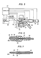
- Fig. 5 shows the total structure of the lean-burn control apparatus according to the present invention.
- a combustion sensor having a function of detecting the misfiring state of an engine and the concentration of NOx comprises a combustion detecting terminal 21 mounted on a combustion chamber 23 of the engine 22 in such a manner as to communicate with the combustion chamber 23, an optical fiber cable for carrying out optical transmission between the combustion detecting terminal 21 and an optical signal processing circuit 25, and the optical signal processing circuit 25.
- the combustion detecting terminal 21 may be either integrally provided with an ignition plug, as shown in Fig. 6, or of a stand-alone type, as shown in Fig. 7.
- the former type of detection terminal is mounted on the apparatus.
- an ignition pulse is provided for the combustion detecting terminal 21 by a controller 27 having a built-in microcomputer through an ignition device 26, so that the combustion detecting terminal also has a function of an ignition plug.
- a combustion light signal or combustion temperature signal which is subjected to photoelectric conversion and signal processing by the optical signal processing circuit 25 is introduced to the controller 27.
- an air fuel ratio signal detected by an air fuel ratio sensor 28 or oxygen sensor
- a throttle valve opening degree information signal supplied from a throttle valve opening degree sensor or a throttle valve opening degree switch 29 is also inputted.
- the controller 27 determines the optimum fuel amount and the optimum ignition timing by the arithmetic processing of these plural signals, and outputs a control signal to both an injector 33 and the ignition device 26.
- the injector 33 injects the optimum amount of fuel to supply it to the engine in accordance with the control signal.
- the ignition device 26 discharges sparks to the ignition plug 21 at the optimum ignition timing.
- the multi-point fuel injection system is adopted, but the present invention is not restricted thereto, and any system such as a carburetor and a sigle-point fuel injection system may be adopted.
- any other air flow rate measuring system may be adopted such as a speed density system for calculating the air flow rate from the revolution number of the engine and the suction negative pressure and a system for calculating the air flow rate from the revolution number of the engine and the opening degree of the throttle valve.
- Fig. 6 is a sectional view of the main part of the fuel detecting terminal of a type in which it is integrally provided with an ignition plug.
- An insulator 37 is secured to these three members 34, 35 and 36 at a sealed portion 38 by heat sealing of a conductive glass sealing material.
- a high voltage for spark discharge is introduced to the central electrode 34 through the high-voltage terminal 35 and the conductive glass sealed portion 38 to carry out spark discharge with a grounding electrode 39.
- the configuration of the end portion 36a of the fused silica fiber on the combustion chamber side may be the optimum configuration selected from among a convex lens, a flat shape , a tapered shape and the like in accordance with the configuration of the combustion chamber, the angle at which the combustion detecting terminal 21 is provided and the like.
- Fig. 7 is a sectional view of the main part of the stand-along type combustion detecting terminal.
- the combustion detecting terminal is provided with a metal housing 41 having a screw portion 40 for mounting the combustion detecting terminal to an engine, and the fused silica fiber 36 provided in such a manner as to go through a central axis of an optical fiber guide terminal 42.
- These three members 41, 36 and 42 are secured to each other at the sealed portion 38 by heat sealing of a glass sealing material, in the same way as in Fig. 6.
- a material having a melting point of about 600 to 800°C is used as the sealing material so as to secure adequate sealing property and adherence even at a high temperature due to heat conduction or radiation from the engine.
- the end portion 36a of the fused silica fiber has a similar structure to that in Fig. 6, explanation thereof being omitted herein.
- a method of detecting misfire it is generally inferred from the magnitude of a revolution change of an engine.
- a method of detecting misfire from the intensity of the combustion flame light or the combustion temperature at the time of combustion is adopted.
- the concentration of NOx is obtained from the combustion temperature by utilizing the fact that there is a corresponding relationship between the combustion temperature in the combustion chamber and the concentration of NOx.
- a method of obtaining the concentration of NOx from the intensity of the combustion light at the wavelength of 5.3 ⁇ m is adopted by utilizing the fact that the emission spectrum of NOx is 5.3 ⁇ m.
- a method of inferring the concentration of NOx from the temperature of the exhaust gas immediately after the combustion chamber is effective, because the temperature of this exhaust gas substantially corresponds to the combustion temperature.
- the method (1) of detecting misfire and NOx from the intensity of the combustion light will first be explained.
- the end portion 36a of the combustion detecting terminal 21 is so designed as to secure sufficient light transmission by polishing the surface or the like, as shown in Figs. 6 and 7.
- Fig. 8 schematically shows the structure of the transmission and processing of an optical signal in this case.
- the combustion light detecting terminal 21 is mounted on each of the combustion chambers 23a to 23d in a manner as shown in Fig. 5.
- the present invention also allows a system for detecting only one specified chamber.
- the optical signals from the combustion light detecting terminals 21a, 21b, 21c and 21d are introduced to the optical signal processing circuit 25 through the respective optical fiber cables 24a, 24b, 24c and 24d.
- As the optical fiber cable 24 a high heat-resistant plastic fiber which can resist a temperature above about 140 to 150°C is preferable.
- a plastic fiber facilitates the formation of an integrated single-core fiber 43 which is composed by melting the plural fibers into one fiber, as shown in Fig. 8.
- the power or combustion stroke of a four-cycle engine is one cycle of the four cycles.
- the power stroke in each combustion chamber is subsequently repeated at every 180 degrees.
- the overlap of the power stroke between each chamber is as small as 60 degrees. Therefore, even if the single-core fiber 43 is used, it is easy to discriminate an optical signal from one cylinder (combustion chamber) from an optical signal from another cylinder, because the optical signal from each combustion chamber is introduced to the optical signal processing circuit 25 intermittently with almost no overlapping. It goes without saying that light may be transmitted from each cylinder through optically separate fibers without integrating the fibers.
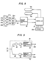
- Fig. 9 shows the structure of the optical signal processing circuit 25.
- the combustion light introduced by the single-core fiber 43 is divided here again into two parts, and introduced to a fiber 44 for NOx concentration detection and a fiber 45 for misfire cycle detection.
- the light for detecting the concentration of NOx is introduced to a first photoelectric transducer 47 through an optical filter 46 which only transmits the light of a wavelength of 5.3 ⁇ m.
- the light intensity corresponding to the concentration of NOx is detected and is converted into electricity.
- the light for detecting misfire is directly introduced to a second photoelectric transducer 48 and is converted into electricity.
- the electrically converted signals are processed by electric signal processing circuits 49 and 50 to output electric signals 49a, 50a which are supplied to a controller 27.
- the misfire signal and the NOx signal obtained in this way are introduced to the controller 27, as shown in Fig. 8, and computed together with a plurality of other engine parameter signals 22a, whereby the air fuel ratio control 13a and the ignition timing control 12a are effected.
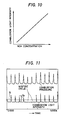
- Fig. 10 shows a relationship between the concentration of NOx and the combustion light intensity signal in the 5.3 ⁇ m zone in the case of adopting the system shown in Figs. 8 and 9. Since they have substantially proportional relationship, an electric signal output from the signal output end 49a in Fig. 9 takes the value substantially corresponding to the concentration of NOx.
- Fig. 11 shows an example of the waveform of a misfiring state detected by the system shown in Figs. 8 and 9.
- the electric signal of the intensity of the combustion light and the combustion pressure signal output from the signal output end 50a in Fig. 9 are detected at the same time for judging misfire.
- a slicing level S is provided as indicated by the symbol S in Fig.
- the engine is judged to be in a misfiring state, and signal pulse corresponing to this misfire cycle is produced and transmitted to the controller 27.
- the misfire information is consecutively transmitted to the controller.
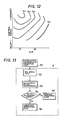
- Fig. 12 shows the average value of the peak values V p for several cycles of the combustion light intensity signals shown in Fig. 11 with respect to the air fuel ratio and the ignition timing represented by a contour line.
- the contour line of V p has a configuration well corresponding to the curve of the misfire boundary in Fig. 4, and judgement as to misfire also may be made by using the average value V p for several cycles.
- Fig. 13 is a flow chart for judging the tolerance limit of NOx.
- the signal is photoelectrically converted into an electric signal through the photoelectric transducer 47 and the electric signal processing circuit 49 shown in Fig. 9, and the electric signal input as a NOx signal to the controller 27 at step 52.
- the concentration of NOx is calculated at the step 53 according to the characteristics shown in Fig. 10. In this case, it is preferable to obtain the average value for several ten power cycles.
- the tolerance value (value satisfying the right-hand side range of the NOx limit line of Fig. 4) is compared with the NOx value calculated at the step 53 and judgement is made as to whether or not the calculated NOx value is in the range of the tolerance limit. If the answer is yes, the process proceeds to step 55 for the ordinary operational mode, while if the answer is no, the process proceeds to step 56 for the collecting operational mode and various controls are executed.
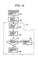
- Fig. 14 is a flow chart for judging a misfiring state.
- the combustion light intensity signal is photoelectrically converted through the photoelectric transducer 48 and the electric signal processing circuit 50 in Fig. 9 at step 57 and a misfire pulse is produced at the electric signal processing circuit 50 at step 58.
- the waveform of the combustion light intensity signal as shown in Fig. 11 is input at the step 58, and judgement is made as to whether the peak value of the waveform of the combustion light intensity signal produced in each power cycle is larger or smaller than a predetermined slicing level S as shown in Fig. 11. If the peak value is larger than S, the cycle is judged to be misfire, and a misfire pulse is produced and outputted for a predetermined period in the corresponding cycle.
- the misfire pulses obtained in this way are inputted to the controller 27 at step 59.
- the misfire pulses produced at the step 59 are counted for a predetermined number of times of power cycles at the step 60 and the count value is supplied to step 61.
- step 61 whether or not the count value is above a predetermined value is judged, and if the answer is yes, the process proceeds to the correcting operational mode 62, while if the answer is no, the process proceeds to the ordinary operational mode 63.
- the portion A in Fig. 13 and the portion A ⁇ in Fig. 14 are executed by the controller 27.
- Fig. 15 is a flow chart integrating the portions A and A ⁇ and showing the details of the correcting operational mode.
- the signals of the engine revolution number N E and the air flow rate Q A are inputted to the controller 27 and further at step 65, signals of air fuel ratio A/F (the value is represented by X) and ignition timing Adv (the value is represented by Y) are inputted to the controller 27.
- the signal of the misfire pulses (M) produced at the electric signal processing circuit 50 in Fig. 9 and the signal of NOx (N) produced at the electric signal processing circuit 49 are inputted to the controller 27.
- the value of N is a waveform peak-held for each power cycle.
- the concentration of NOx is converted from the NOx signal (N) inputted at the step 66 by using the characteristics shown in Fig. 10.
- the thus-converted concentration values of NOx for given several ten power cycles are averaged to calculated the average value N .
- the number of the misfire pulses M in a predetermined number of times of power cycles is counted at step 73, and the count value Mx is supplied to step 74, at which whether or not the count value Mx is smaller than a predetermined number is judged. If Mx is larger than the predetermined number, the process proceeds to the steps 72 and 71, while if Mx is smaller, the process proceeds to the steps 69 and 71. At the steps 69, 70, 70 and 72, operation is carried out only when signals are transmitted at the same time from two signal lines.
- the processing is executed only when the NOx is out of the tolerance limit and misfire is within the tolerance limit.
- the operation is carried out in the case where the signals are situated at the points such as P3, P5 and P9 in Fig. 4.
- the amount of air or fuel is controlled by this control signal, and the mixture having a leaner air fuel ratio than that at the previous time is supplied to the engine.
- this mode is repeated so as to move the NOx signal and misfire signal to the target control range, for example, to the point P4, which satisfies both conditions, and thereafter the process proceeds to step 71 for the ordinary operational mode.
- the signals enter the range, for example, to the points P6 and P8, in which NOx is in the tolerance limit but misfire exceeds the tolerance value. This state is treated at the step 72.
- controller 27 It is effective to add the controller 27 a function of storing A/F and Adv in a map table made from the N E and the Q A when A/F and Adv are moved to the target control range in this way and renewing these values when new A/F and Adv are obtained by executing similar control at the preceding cycle. It is also effective to obtain the misfire boundary line and NOx limit line by the repetition of the above-described controls and store these lines on the map table of A/F and Adv.
- the method (2) namely, the method of detecting and controlling misfire and NOx from the detected combustion temperature will now be explained.
- Figs. 16 to 18 show in example of a detector 110 suitable for detecting combustion temperature which can be used for the combustion detecting terminal 21 used in the system shown in Fig. 5.
- the detector 110 comprises an end portion of an optical transmission element 111 made of quartz (or fused silica fiber) having a diameter of about 1 mm and having a resistance to a temperature of 300 to 1,500°C in the combustion chamber 23, and a thin black body film 112 of iridium having a linear expansion coefficient approximate to that of quartz and attached to the end portion of the optical transmission element 111.
- the end portion of the element 111 is obliquely cut to provide a large end surface for detecting spectral radiant energy.
- the black body film 112 is attached to the end so as to cover the end portion of the element including the cut surface.
- the black body film 112 is covered with a protective film 113 made of high heat-resistant material such as quartz and ceramic to prevent the black body film from being peeled from the element 111 and to prevent the deterioration of the black body film 112 due to oxidization and corrosion.
- a protective film 113 made of high heat-resistant material such as quartz and ceramic to prevent the black body film from being peeled from the element 111 and to prevent the deterioration of the black body film 112 due to oxidization and corrosion.
- the black body film 112 is formed on the end portion of the element 111 by evaporation, sputtering or the like.
- the protective film 113 is also formed on the surface of the element 111 by evaporation, sputtering or the like.
- the protective film 113 is fused to the element 111 at an end thereof, so that it is firmly adhered to the element 111.
- a sapphire rod may be used in place of the element 111.
- the black body film 112 and the protective film 113 preferably have a thickness of as small as about 2 to 5 ⁇ m from the point of view of heat capacity. However, when a sufficient adhesion is not obtained, the thickness of those films is increased.
- the temperature in the combustion chamber 23 of the engine 22 varies with a period of several KHz, and the pressure in the combustion chamber 23 rapidly changes, but the use of quartz as the optical transmission element 111 and iridium as the black body 112 realizes a firm structure having a good thermal response because quartz and iridium have good adhesion and approximately the same linear expansion coefficient.
- the detector 110 including a part of the optical transmission elements 111, it is also possible to use platinum, zirconium nitride or graphite as the black body 112, and, if measurement of a high temperature is necessary, to use sapphire as the optical transmission element.
- the detector 110 and part of the optical transmission element 111 is located in the combustion chamber 23 of an engine and secured to a wall portion 22a of the combustion chamber 23 by screwing.
- a metal pipe 114 is secured to the outer periphery of the optical transmission element 111 by a fused glass 115 and the outer periphery of the metal pipe 114 is threaded.
- a thread bore engaging the metal pipe 114 is formed on the wall 22a of the combustion chamber 23. The detector 110 and the optical transmission element 111 is screwed into and fixed on the wall 22a through the metal pipe 114.
- a connecting member 116 is secured by screwing.
- the connecting member 116 accommodates a connector 117 for connecting an optical fiber 118 to the optical transmission element 111. Therefore, when the connecting member 116 is connected to the projecting end of the metal pipe 114, the optical transmission element 111 and the optical fiber 118 are optically connected to each other.
- the pressure in the combustion chamber 23 of the engine is prevented from leaking to the outside.
- Another example of the detector is of a plug type as shown in Fig. 19.
- the detector portion 36b is an end of fused silica or quartz fiber 36 which is disposed in a central electrode 34.
- the other construction including a high voltage terminal 35, electrically insulating porcelain 37, a sealing 38 and a grounding electrode is the same as in Fig. 6.
- the detector portion 36b is the same as in Figs. 16 and 17. Namely, it comprises the fiber 36, a black body film adhered on a surface of and end portion of the fiber 36, and a protective film.
- the plug type detector has functions of detection of temperature and ignition of fuel air mixture in the combustion chamber.
- a black body produces radiant energy to a temperature.
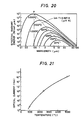
- Fig. 20 shows a relationship between the spectral radiant energy and wavelength and temperature of a black body. It is possible to infer the temperature by detecting the radiant energy with respect to a certain wavelength. For example, the temperature of 1,000 to 5,000°C is obtained by detecting the radiant energy at the wavelength of a point P in Fig. 20.
- Fig. 21 shows the characteristics of optical current with respect to the combustion temperature of a photoelectric transducer.
- the optical current changes on a log scale with respect to a change in temperature. Therefore, in the case of detection in a wide temperature range, a technique of logarithmically compressing the optical current through a log diode for linearization or the like is added.
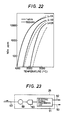
- Fig. 22 shows a relationship between combustion temperature and NOx.
- concentration of NOx there is little difference in the concentration of NOx between 1 atm and 50 atm in the pressure in the combustion chamber and it is understood that the influence of the pressure is negligible in an ordinary combustion state. Therefore, if the air fuel ratio is detected at a specified time, the concentration of NOx is easily calculated from the combustion temperature at that time. Since the value corresponding to the average air fuel ratio is detected by the air fuel ratio sensor 28, as shown in Fig. 5, if the combustion temperature is detected, it is possible to calculate the concentration of NOx.
- Fig. 23 shows the structure of the signal processing circuit 25 in the case of adopting the combustion temperature detecting system.
- the heat radiating light from the black body film 112 at the end portion 110 or 36b introduced by the single-core integrated fiber 43 is introduced to a photoelectric transducer 90 through an optical filter 89 which transmits only light of a specific wavelength (e.g., 700 nm). Since the intensity of the radiating light is a function of a temperature, information on the combustion temperature is obtained by photoelectric convention of the light intensity. In case of a misfire cycle, the combustion temperature naturally does not rise.
- a specific wavelength e.g. 700 nm
- the cycle is judged to be a misfire cycle and the signal is passed through a comparator and a wave shaper, thereby outputting a misfire signal. Since the absolute value of the combustion temperature is substantially proportional to the concentration of NOx, it is possible to output a signal corresponding to the concentration of NOx from the peak value or the integrated value of the photoelectrically converted electric signal. These processings are carried out by an electric signal processing circuit 91.
- the electric signal processing circuit 91 forms the waveforms of the combustion temperature signals for the respective cycles which are substantially equal to the waveforms of the combustion temperature signals shown in Fig. 11 by utilizing the characteristics shown in Figs. 20 and 21.
- a given slicing level is set by utilizing the fact that the combustion temperature does not rise at the time of misfire, and when the combustion temperature signal in a power cycle does not exceed the slicing level, one misfire pulse is produced in that power cycle and the signal is output from an output end 92. From an output end 93, the peak value of the combustion signal which is peak held at each power cycle is output.
- Fig. 24 is a flow chart for judging the tolerance limit of NOx.
- the signal photoelectrically converted by the photoelectric transducer 90 and peak held at each power cycle by the electric signal processing circuit 91 in Fig. 23 (at step 94) is transmitted to the controller 27 and inputted as a combustion temperature signal at step 95.
- an air fuel ratio signal is inputted from the air fuel ratio sensor 28 shown in Fig. 5.
- the concentration of NOx is calculated from the combustion temperature by using the characteristics curve of NOx with respect to the air fuel ratio (ratio of excess air) such as that shown in Fig. 22.
- the average value of the concentrations of NOx for ten cycles is further calculated, and the result is supplied to step 100 as an average NOx value.
- the tolerane value of NOx value are compared with each other to judge whether or not the average value is within the tolerance limit. If yes, the process proceeds to ordinary operational mode 101, while if no, the process proceeds to the correcting operational mode 102 and the same control as that in Fig. 15 is carried out.
- Fig. 25 is a flow chart for judging a misfiring state.
- the misfire pulse obtained by photoelectrically converting a signal by the photoelectric transducer 90 (at the step 94) and produced by the electric signal processing circuit 91 (at the step 103) in Fig. 23 is transmitted to the controller 27 and inputted as a misfire pulse at step 104.
- the number of the misfire pulses is counted for a predetermined power cycles, and judgment is made as to whether or not the value is above a preset value. If the value is less than the preset value, the combustion state is judged to be a non-misfiring state, and the process proceeds to the step 101.
- the state is judged to be a misfiring state, and the process proceeds to the step 102, and the same control as that in Fig. 24 and the portion B ⁇ in Fig. 25 are carried out by the controller 27.
- An engine control system employing the above-mentioned temperature detector such as the detector disclosed in Figs. 16 to 19 is capable of a precise and effective control of an internal combustion engine because the sensor directly detects the temperature in the combustion chamber of the engine.
- Such engine control apparatus is applicable to a knock control of the engine.
- An example, of the knock control will be described hereunder, refferring to Figs. 26 to 27.
- a no knock state
- a knock state a knock state
- a trace knock state a knock state
- the optimum knock state is of a trace knock from a viewpoint of engine power output.
- the knock state or strength can be changed by chaning ignition timing.
- Occurrence of the knock influences change in temperature in the combustion chamber, so that the knock strength can be detected through detection of the temperature in the combustion chamber.
- a detector 110 for detecting a change in the temperature in the combustion chamber 23 is disposed, and the signal detected by the detector 110 is inputted to a band-pass filter 120 by an optical transmission element 111, a connector 116 and an optical fiber 118.
- the output terminal of the band-pass filter 120 is connected to the input terminal of a photo detector 130, and the output terminal of the photo detector 130 is connected to the input terminal of a shaping circuit 140.
- the shaping circuit 140 comprises a signal amplifier 141, a linear processing part 142, and a high pass filter 143.
- the output terminal of the photo detector 130 is connected to the input terminal of the signal amplifier 141, the output terminal of which is connected to the input terminal of the linear processing portion 142.
- the output terminal of the linear processing part 142 is connected to the input terminal of the high pass filter 143, the output terminal of which is, in turn, connected to the input terminal of an ignition timing correcting means 150.
- the detector 110 is the same as disclosed in Figs. 16 to 18.
- the detector as shown in Fig. 19 also can be used for the knock control apparatus.
- the detector 110 disposed in the combustion chamber 23 receives heat, and the black body or film 112 generally produces radiant energy such as that shown in Fig. 20 in correspondence with a temperature. Accordingly, a temperature at a certain wavelength is obtained by measuring the radiant energy at that wavelength.
- a band-pass filter having a transmission range of 0.6 to 0.7 ⁇ m is used as the band-pass filter 120 in Fig. 26, so as to detect a temperature in the range of 1,000 to 2,500°C.
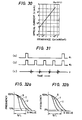
- an Si photo transistor having a circuit structure such as that shown in Fig. 27a is used as the photo detector 130, and a load resistance 131 is connected between the emitter and the ground at the output stage of the photo transistor.
- a bias voltage Vcc is applied between the collector and the ground of the photo transistor.
- Fig. 29 shows the characteristics of the Si photo transistor used as the photo detector 130 in this embodiment. It is possible to detect light in the wavelength range of 500 to 1,200 nm.
- a load resistance of 0.1 k ⁇ is connected as the load resistance 131 in Fig. 27a in this embodiment.
- the output signal with respect to the input signal shown in Fig. 27b takes a same form such as that shown in Fig. 27c.
- the value of 0.1 k ⁇ is selected as the load resistance, as described above.
- a cylinder discrimination signal such as those shown by (a) and (b) of Fig. 31 and a knock such as that shown by (c) of Fig. 31 are produced from the engine.
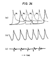
- a change in the temperature corresponding to the spectral radiant energy of the knock which is indicated by the symbol W1 to W4 in (a) of Fig. 34 is detected by the detector 110 shown in Fig. 26 in correspondence with each cylinder.
- the thus-detected signal is taken out of the combustion chamber 23 of the engine by the optical transmission element 111 as a time series optical signal such as that shown by (b) of Fig. 34, and input to the band-pass filter 120 by the optical fiber 118 through the connecting member 116.
- the band-pass filter 120 has a pass band at 0.6 to 0.7 ⁇ m, and an optical signal Qc corresponding to a combustion temperature of 1,000 to 2,500°C in the combustion chamber 23 is supplied to the photo detector 130 through the band-pass filter 120.
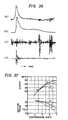
- the photo detector 130 is composed of the Si photo transistor, as described above. As shown in Fig. 33, a collector current such as that shown by (b) is caused to flow in accordance with the above-described optical signal such as that shown by (a), so that an output voltage signal such as that shown by (c) is obtained.
- the output voltage signal V c is amplified by the signal amplifier 141 so as to form an output voltage signal V A such as that shown by (d) of Fig. 33, which is further linearized by the linear processing part 142 so as to form an output voltage signal V L such as that shown by (e) of Fig. 33.
- the output voltage signal V L is supplied as an input to the high pass filter 143 having a pass band at above 4 KHz.
- the high pass filter 143 takes only the knock component out of the output voltage signal V L , and a knock signal V S such as that shown by (f) of Fig. 33 is inputted from the high pass filter 143 to the ignition time correcting means 150.
- a knock signal V S such as that shown by (d) of Fig. 36 is supplied to the output terminal of the shaping circuit 140.
- (c) of Fig. 36 shows that the knock signal shaped in the same process as in the present invention and detected by a piezoelectric element is mixed with the vibration caused by other factors than knock, thereby making discrimination between them impossible.
- measurement in Fig. 36 was carried out when the number of revolutions of the engine was 6,000 rpm.
- the ignition timing correcting means 150 corrects the ignition timing of the engine in accordance with the knock signal V S which has been inputted to the output terminal of the shaping circuit 140.
- Figs. 32a and 32b are the curves obtained by the statistical processing of the cumulative frequency distribution of the S values for 1024 igniting operations which are obtained by converting the optical signals after passing them through the band-pass filter 120 shown by (c) of Fig. 31 relative to the state S in which no knock is generated, the state T in which trace knock is generated and the state U in which knock is generated, respectively.
- the ignition timing of the engine is corrected in the following way.
- step 163 judgement is made as to whether or not the number N of revolutions of the engine is not more than 4,000 rpm, and if the answer is yes, the process proceeds to step 165.
- the S/L value is set at the position at which the sensor signal exceeds the slicing level by 10% in the trace knock state, as shown in Fig. 32a.
- step 163 the process proceeds to step 164. Since it is dangerous that the S values larger than those in the trace knock state continue when the engine is rotated at such a high speed, the S/L value is set at the position at which the sensor signal exceeds the slicing level by 2% in the trace knock state, as shown in Fig. 32b.
- step 166 the knock signal V S of one cylinder obtained in the above-described way is subjected to A/D conversion to obtain the S value.
- step 167 the thus-obtained S value is compared with the S/L value which has been obtained in advance.
- the engine is judged to be in the knock state, whereby the delay control of the ignition timing is carried out.
- the S value is smaller than the preset S/L value, it is judged that no knock is generated, whereby the advanced control of the ignition timing is executed.
- the ratio f the S values which are judged to show the knock state and the ratio of advanced control angle/delay control angle are controlled in combination with each other. More specifically, if it is assumed that the generation ratio of the S values larger than the S/L is 10%, since the advance control is carried out once for every ten igniting operations in the state in which the ignition timing is stably controlled, the ratio of the advanced control angle to the delay control angle is set at 1 : 10.
- the ignition time is delayed by ⁇ 1
- the ignition timing is advanced by ⁇ 2
- ⁇ 1/ ⁇ 2 is set at 1/10.
- step 672 to judge whether or not n and T P are the same. If the answer is in the affirmative, the operation of the steps 166 to 172 are repeated. On the other hand, if the answer is in the negative at the step 172, ⁇ is reloaded as ⁇ 0 at step 173.
- the ratio of the advanced control angle to the delay control angle is set at 1 : 10 in the case where the rotational speed of the engine is lower than 4,000 rpm, and it is set at 1 : 50 in the case where the rotational speed of the engine is 4,000 rpm or higher.
- this embodiment of the present invention since a change in the temperature in the combustion chamber is detected by utilizing the radiation of a black body and a knock signal is obtained on the basis of this detected signal, it impossible to detect the strength of the knock without an error due to vibration even in a high-speed rotational state of the engine or an error due to the detection surface smudged by soot or the like. Since the ignition timing of the engine is corrected on the basis of the thus-detected strength of the knock, this embodiment of the present invention enables the engine to be operated constantly in the trace knock state, thereby obtaining the output of the maximum efficiency.
Landscapes
- Engineering & Computer Science (AREA)
- Chemical & Material Sciences (AREA)
- Combustion & Propulsion (AREA)
- Mechanical Engineering (AREA)
- General Engineering & Computer Science (AREA)
- Physics & Mathematics (AREA)
- General Physics & Mathematics (AREA)
- Signal Processing (AREA)
- Combined Controls Of Internal Combustion Engines (AREA)
- Ignition Installations For Internal Combustion Engines (AREA)
Priority Applications (1)
| Application Number | Priority Date | Filing Date | Title |
|---|---|---|---|
| EP90118320A EP0412578B1 (de) | 1987-04-21 | 1988-04-21 | Gerät und Methode zur Steuerung der Verbrennung für einen Verbrennungsmotor |
Applications Claiming Priority (4)
| Application Number | Priority Date | Filing Date | Title |
|---|---|---|---|
| JP62096123A JPH0759934B2 (ja) | 1987-04-21 | 1987-04-21 | ノツク制御装置 |
| JP96123/87 | 1987-04-21 | ||
| JP138071/87 | 1987-06-03 | ||
| JP62138071A JPH0794808B2 (ja) | 1987-06-03 | 1987-06-03 | リーンバーンエンジン制御装置及び制御方法 |
Related Child Applications (2)
| Application Number | Title | Priority Date | Filing Date |
|---|---|---|---|
| EP90118320A Division EP0412578B1 (de) | 1987-04-21 | 1988-04-21 | Gerät und Methode zur Steuerung der Verbrennung für einen Verbrennungsmotor |
| EP90118320.2 Division-Into | 1990-09-24 |
Publications (3)
| Publication Number | Publication Date |
|---|---|
| EP0288056A2 true EP0288056A2 (de) | 1988-10-26 |
| EP0288056A3 EP0288056A3 (en) | 1989-01-18 |
| EP0288056B1 EP0288056B1 (de) | 1991-04-10 |
Family
ID=26437352
Family Applications (3)
| Application Number | Title | Priority Date | Filing Date |
|---|---|---|---|
| EP88106402A Expired - Lifetime EP0288056B1 (de) | 1987-04-21 | 1988-04-21 | Steuervorrichtung für Motoren mit innerer Verbrennung |
| EP90118320A Expired - Lifetime EP0412578B1 (de) | 1987-04-21 | 1988-04-21 | Gerät und Methode zur Steuerung der Verbrennung für einen Verbrennungsmotor |
| EP93114333A Expired - Lifetime EP0579271B1 (de) | 1987-04-21 | 1988-04-21 | Verfahren zum Erfassen von Fehlzündungen in einer Brennkraftmaschine |
Family Applications After (2)
| Application Number | Title | Priority Date | Filing Date |
|---|---|---|---|
| EP90118320A Expired - Lifetime EP0412578B1 (de) | 1987-04-21 | 1988-04-21 | Gerät und Methode zur Steuerung der Verbrennung für einen Verbrennungsmotor |
| EP93114333A Expired - Lifetime EP0579271B1 (de) | 1987-04-21 | 1988-04-21 | Verfahren zum Erfassen von Fehlzündungen in einer Brennkraftmaschine |
Country Status (4)
| Country | Link |
|---|---|
| US (2) | US4887574A (de) |
| EP (3) | EP0288056B1 (de) |
| KR (1) | KR930000346B1 (de) |
| DE (3) | DE3851231T2 (de) |
Cited By (11)
| Publication number | Priority date | Publication date | Assignee | Title |
|---|---|---|---|---|
| EP0441603A2 (de) * | 1990-02-09 | 1991-08-14 | Lucas Industries Public Limited Company | Zündausfallerfassungsmethode |
| DE4444972A1 (de) * | 1993-12-17 | 1995-06-22 | Fuji Heavy Ind Ltd | Elektronisches Steuersystem und Steuerverfahren für einen Motor |
| AT301U1 (de) * | 1993-01-28 | 1995-07-25 | Jenbacher Energiesysteme Ag | Einrichtung zur regelung des kraftstoff-luft- verhaeltnisses und/oder des zuendzeitpunktes eines verbraeltnisses und/oder des zuendzeitpunktes eines verbrennungsmotors |
| DE19622848A1 (de) * | 1995-06-07 | 1996-12-12 | Cummins Engine Co Inc | System und Verfahren zur Detektion von Fehlzündungen in einem Motor |
| US6243641B1 (en) | 1995-06-07 | 2001-06-05 | Cummins Engine Company, Inc. | System and method for detecting engine cylinder misfire |
| EP0922846A3 (de) * | 1997-12-12 | 2002-05-15 | MAN Nutzfahrzeuge Aktiengesellschaft | Verfahren zur NOx-Reduzierung an gemischverdichtenden Brennkraftmaschinen |
| DE4447858C2 (de) * | 1993-12-17 | 2002-09-26 | Fuji Heavy Ind Ltd | Elektronisches Steuersystem und Steuerverfahren für einen Motor |
| WO2004090311A1 (de) * | 2003-04-09 | 2004-10-21 | Daimlerchrysler Ag | Verfahren zum betrieb einer brennkraftmaschine mit selbstzündung |
| US9279406B2 (en) | 2012-06-22 | 2016-03-08 | Illinois Tool Works, Inc. | System and method for analyzing carbon build up in an engine |
| WO2016191773A1 (de) * | 2015-06-03 | 2016-12-08 | Ge Jenbacher Gmbh & Co Og | Verfahren zum betreiben einer brennkraftmaschine |
| EP3397852A4 (de) * | 2015-12-30 | 2020-02-12 | Cummins, Inc. | Steuerungsstrategien für ottomotoren mit magerer verbrennung |
Families Citing this family (43)
| Publication number | Priority date | Publication date | Assignee | Title |
|---|---|---|---|---|
| DE3829797A1 (de) * | 1988-09-02 | 1990-03-15 | Bosch Gmbh Robert | Elektronische motorsteuerung mit funktionspruefung fuer die zuendungsendstufe |
| KR930009907B1 (ko) * | 1988-10-04 | 1993-10-13 | 미쯔비시 덴끼 가부시끼가이샤 | 내연기관 제어장치 |
| WO1991013248A1 (en) * | 1990-02-26 | 1991-09-05 | Barrack Technology Limited | Engine condition determining and operating method |
| US5099683A (en) * | 1990-05-22 | 1992-03-31 | Barrack Technology Limited | Method and apparatus for determining certain operating and running parameters in an internal combustion engine |
| US5067463A (en) * | 1990-02-26 | 1991-11-26 | Barrack Technology Limited | Method and apparatus for operating an engine |
| US5103789A (en) * | 1990-04-11 | 1992-04-14 | Barrack Technology Limited | Method and apparatus for measuring and controlling combustion phasing in an internal combustion engine |
| US5038744A (en) * | 1990-06-21 | 1991-08-13 | Barrack Technology Limited | Method and apparatus for controlling spark ignition in an internal combustion engine |
| US5219227A (en) * | 1990-08-13 | 1993-06-15 | Barrack Technology Limited | Method and apparatus for determining burned gas temperature, trapped mass and NOx emissions in an internal combustion engine |
| FR2667113B1 (fr) * | 1990-09-26 | 1993-06-25 | Semt Pielstick | Procede de surveillance de l'emission d'oxydes d'azote par un moteur a combustion interne. |
| JPH04262039A (ja) * | 1991-02-18 | 1992-09-17 | Mitsubishi Electric Corp | 内燃機関の失火検出装置 |
| US5373448A (en) * | 1991-04-24 | 1994-12-13 | Hitachi, Ltd. | Knock detection device for an internal combustion engine |
| US5164999A (en) * | 1991-05-20 | 1992-11-17 | Johnson Matthey, Inc. | Blackbody fired on silica fiber |
| US5257496A (en) * | 1992-05-05 | 1993-11-02 | General Electric Company | Combustion control for producing low NOx emissions through use of flame spectroscopy |
| US5285676A (en) * | 1992-08-03 | 1994-02-15 | Motorola, Inc. | Air-fuel ratio measurement apparatus and method therefor |
| US6456927B1 (en) * | 1993-03-22 | 2002-09-24 | Motorola, Inc. | Spectral knock detection method and system therefor |
| JP2807736B2 (ja) * | 1993-08-19 | 1998-10-08 | 本田技研工業株式会社 | 内燃機関の燃焼状態判定装置 |
| JP2807737B2 (ja) * | 1993-09-10 | 1998-10-08 | 本田技研工業株式会社 | 内燃エンジンの燃焼状態検出装置 |
| DE4402938A1 (de) * | 1994-02-01 | 1995-08-03 | Fev Motorentech Gmbh & Co Kg | Verfahren zur Steuerung eines Kolbenverbrennungsmotors unter Einhaltung der Laufgrenze |
| SE508563C2 (sv) * | 1994-02-22 | 1998-10-12 | Scania Cv Ab | Sensor för detektering av joniseringsgrad i en förbränningsmotors förbränningsrum jämte förbränningsmotor försedd med joniseringssensor |
| US5467185A (en) * | 1994-07-15 | 1995-11-14 | General Electric Company | Emissions control for internal combustion engine |
| US5763888A (en) * | 1995-01-30 | 1998-06-09 | Ametek Aerospace Products, Inc. | High temperature gas stream optical flame sensor and method for fabricating same |
| US5553575A (en) * | 1995-06-16 | 1996-09-10 | Servojet Products International | Lambda control by skip fire of unthrottled gas fueled engines |
| JP3268517B2 (ja) * | 1995-07-28 | 2002-03-25 | 株式会社ユニシアジェックス | 内燃機関における燃焼改善機構の診断装置 |
| US5700954A (en) * | 1996-10-31 | 1997-12-23 | Ford Global Technologies, Inc. | Method of controlling fuel during engine misfire |
| US5961314A (en) * | 1997-05-06 | 1999-10-05 | Rosemount Aerospace Inc. | Apparatus for detecting flame conditions in combustion systems |
| US5983866A (en) * | 1997-10-27 | 1999-11-16 | Caterpillar Inc. | Diagnostic apparatus and method for a combustion sensor feedback system |
| US6931836B2 (en) * | 1997-12-12 | 2005-08-23 | Man Nutzfahrzeuge Ag | Method for NOx reduction of externally-ignited, explosion, internal combustion engines |
| US6363778B1 (en) * | 1998-12-17 | 2002-04-02 | Honeywell International Inc. | Engine misfire monitor |
| US7112796B2 (en) * | 1999-02-08 | 2006-09-26 | General Electric Company | System and method for optical monitoring of a combustion flame |
| JP2000240550A (ja) * | 1999-02-18 | 2000-09-05 | Mitsubishi Electric Corp | 内燃機関の失火検出装置 |
| DE10105366A1 (de) * | 2001-02-06 | 2002-08-29 | Siemens Ag | Elektrische Verbindungsstruktur im Kraftfahrzeug |
| DE10107595A1 (de) * | 2001-02-17 | 2002-08-29 | Bayerische Motoren Werke Ag | Elektromagnetischer Ventiltrieb |
| AT5153U1 (de) * | 2001-03-22 | 2002-03-25 | Avl List Gmbh | Optischer sensor zur erfassung von verbrennungsvorgängen |
| DE10332517A1 (de) * | 2003-07-17 | 2005-02-03 | Robert Bosch Gmbh | Verfahren und Vorrichtung zum Betreiben einer Brennkraftmaschine |
| US8469700B2 (en) | 2005-09-29 | 2013-06-25 | Rosemount Inc. | Fouling and corrosion detector for burner tips in fired equipment |
| ITBO20050789A1 (it) * | 2005-12-23 | 2007-06-24 | Ferrari Spa | Metodo per il controllo dell'anticipo di accensione in un motore a combustione interna. |
| FR2899686B1 (fr) * | 2006-04-07 | 2008-06-06 | Ecoles Des Mines De Nantes | Procede et dispositif de detection d'une phase de fonctionnement perturbee d'un moteur a allumage commande se traduisant par le phenomene de cliquetis |
| US20080104944A1 (en) * | 2006-10-31 | 2008-05-08 | Caterpillar Inc. | Engine emissions control system |
| AT503276B1 (de) | 2007-05-31 | 2010-06-15 | Avl List Gmbh | Verfahren zur bewertung des zustandes eines kraftstoff/luft-gemisches |
| US8265851B2 (en) * | 2009-05-18 | 2012-09-11 | Closed-Loop Engine Technology, Llc | Method of controlling engine performance |
| JP6088397B2 (ja) * | 2013-10-15 | 2017-03-01 | 日本特殊陶業株式会社 | 点火時期制御装置および点火時期制御システム |
| US10544726B2 (en) * | 2017-11-06 | 2020-01-28 | Ford Global Technologies, Llc | Methods and systems for a fuel injector |
| GB2597965B (en) * | 2020-08-12 | 2022-11-23 | Caterpillar Energy Solutions Gmbh | Misfire classification method and control unit for an internal combustion engine |
Citations (6)
| Publication number | Priority date | Publication date | Assignee | Title |
|---|---|---|---|---|
| JPS57186040A (en) * | 1981-05-13 | 1982-11-16 | Hitachi Ltd | Air-fuel ratio feedback controller |
| JPS5813137A (ja) * | 1981-07-18 | 1983-01-25 | Yoshiyuki Morita | 内燃機関の制御装置 |
| US4446723A (en) * | 1981-03-20 | 1984-05-08 | Robert Bosch Gmbh | Optical combustion event sensor structure particularly knock sensor for an internal combustion engine |
| JPS6017239A (ja) * | 1983-07-07 | 1985-01-29 | Nissan Motor Co Ltd | 内燃機関の燃焼制御装置 |
| DE3410067A1 (de) * | 1984-03-20 | 1985-09-26 | Robert Bosch Gmbh, 7000 Stuttgart | Verfahren zur regelung einer brennkraftmaschine mit erfassung des verlaufs der lichtintensitaet |
| US4576486A (en) * | 1983-08-23 | 1986-03-18 | The United States Of America As Represented By The Secretary Of Commerce | Optical fiber thermometer |
Family Cites Families (9)
| Publication number | Priority date | Publication date | Assignee | Title |
|---|---|---|---|---|
| US3067610A (en) * | 1958-10-02 | 1962-12-11 | Gen Motors Corp | Gated amplitude indicator |
| GB1483612A (en) * | 1974-07-05 | 1977-08-24 | Lumenition Ltd | Detection of combustion in internal combustion engines |
| DE3111135A1 (de) * | 1980-06-20 | 1982-03-11 | Robert Bosch Gmbh, 7000 Stuttgart | Verfahren zum regeln der verbrennung in den brennraeumen einer brennkraftmaschine |
| DE3108460A1 (de) * | 1981-02-13 | 1982-11-04 | Pischinger, Franz, Prof. Dipl.-Ing. Dr.Techn., 5100 Aachen | Verfahren zum erkennen klopfender verbrennung sowie vorrichtung zur durchfuehrung des verfahrens |
| US4437334A (en) * | 1981-02-13 | 1984-03-20 | Franz Pischinger | Method and apparatus for detecting knocking combustion |
| ATE43406T1 (de) * | 1981-07-23 | 1989-06-15 | Ail Corp | Verfahren und einrichtung zur erzeugung eines verbrennungsbeginnsignal fuer eine selbszuendende brennkraftmaschine. |
| JPS59162329A (ja) * | 1983-03-07 | 1984-09-13 | Nippon Carbureter Co Ltd | エンジンの燃料制御方法 |
| JPS6056150A (ja) * | 1983-09-06 | 1985-04-01 | Nissan Motor Co Ltd | エンジンの制御装置 |
| JPH0684939B2 (ja) * | 1986-08-13 | 1994-10-26 | 株式会社日立製作所 | 空燃比検出式燃焼センサ |
-
1988
- 1988-04-20 US US07/184,076 patent/US4887574A/en not_active Ceased
- 1988-04-21 EP EP88106402A patent/EP0288056B1/de not_active Expired - Lifetime
- 1988-04-21 EP EP90118320A patent/EP0412578B1/de not_active Expired - Lifetime
- 1988-04-21 EP EP93114333A patent/EP0579271B1/de not_active Expired - Lifetime
- 1988-04-21 DE DE3851231T patent/DE3851231T2/de not_active Expired - Fee Related
- 1988-04-21 DE DE3855849T patent/DE3855849T2/de not_active Expired - Fee Related
- 1988-04-21 DE DE8888106402T patent/DE3862339D1/de not_active Expired - Lifetime
- 1988-04-21 KR KR1019880004510A patent/KR930000346B1/ko not_active IP Right Cessation
-
1991
- 1991-12-17 US US07/808,812 patent/USRE34234E/en not_active Expired - Lifetime
Patent Citations (6)
| Publication number | Priority date | Publication date | Assignee | Title |
|---|---|---|---|---|
| US4446723A (en) * | 1981-03-20 | 1984-05-08 | Robert Bosch Gmbh | Optical combustion event sensor structure particularly knock sensor for an internal combustion engine |
| JPS57186040A (en) * | 1981-05-13 | 1982-11-16 | Hitachi Ltd | Air-fuel ratio feedback controller |
| JPS5813137A (ja) * | 1981-07-18 | 1983-01-25 | Yoshiyuki Morita | 内燃機関の制御装置 |
| JPS6017239A (ja) * | 1983-07-07 | 1985-01-29 | Nissan Motor Co Ltd | 内燃機関の燃焼制御装置 |
| US4576486A (en) * | 1983-08-23 | 1986-03-18 | The United States Of America As Represented By The Secretary Of Commerce | Optical fiber thermometer |
| DE3410067A1 (de) * | 1984-03-20 | 1985-09-26 | Robert Bosch Gmbh, 7000 Stuttgart | Verfahren zur regelung einer brennkraftmaschine mit erfassung des verlaufs der lichtintensitaet |
Non-Patent Citations (4)
| Title |
|---|
| PATENT ABSTRACTS OF JAPAN, Vol. 7, No. 31 (M-192)(1176), 8th February 1983; & JP-A-57 186 040 (HITACHI SEISAKUSHO K.K.) 16-11-1982. * |
| PATENT ABSTRACTS OF JAPAN, Vol. 7, No. 89 (M-207)(1234), 13th April 1983; & JP-A-58 013 137 (YOSHIYUKI MORITA) 25-01-1983 * |
| PATENT ABSTRACTS OF JAPAN, Vol. 9, No. 135 (M-386)(1858), 11th June 1985; & JP-A-60 017 239 (NISSAN JIDOSHA K.K.) 29-01-1985. * |
| SAE-paper 850380 * |
Cited By (16)
| Publication number | Priority date | Publication date | Assignee | Title |
|---|---|---|---|---|
| EP0441603A3 (en) * | 1990-02-09 | 1992-01-08 | Lucas Industries Public Limited Company | Misfire detection |
| EP0441603A2 (de) * | 1990-02-09 | 1991-08-14 | Lucas Industries Public Limited Company | Zündausfallerfassungsmethode |
| AT301U1 (de) * | 1993-01-28 | 1995-07-25 | Jenbacher Energiesysteme Ag | Einrichtung zur regelung des kraftstoff-luft- verhaeltnisses und/oder des zuendzeitpunktes eines verbraeltnisses und/oder des zuendzeitpunktes eines verbrennungsmotors |
| DE4447858C2 (de) * | 1993-12-17 | 2002-09-26 | Fuji Heavy Ind Ltd | Elektronisches Steuersystem und Steuerverfahren für einen Motor |
| DE4444972A1 (de) * | 1993-12-17 | 1995-06-22 | Fuji Heavy Ind Ltd | Elektronisches Steuersystem und Steuerverfahren für einen Motor |
| DE4444972C2 (de) * | 1993-12-17 | 2000-08-31 | Fuji Heavy Ind Ltd | Elektronisches Steuerverfahren und Steuersystem für einen Motor |
| DE19622848A1 (de) * | 1995-06-07 | 1996-12-12 | Cummins Engine Co Inc | System und Verfahren zur Detektion von Fehlzündungen in einem Motor |
| US6243641B1 (en) | 1995-06-07 | 2001-06-05 | Cummins Engine Company, Inc. | System and method for detecting engine cylinder misfire |
| DE19622848C2 (de) * | 1995-06-07 | 2002-11-14 | Cummins Engine Co Inc | System und Verfahren zur Detektion von Fehlzündungen in einem Motor |
| EP0922846A3 (de) * | 1997-12-12 | 2002-05-15 | MAN Nutzfahrzeuge Aktiengesellschaft | Verfahren zur NOx-Reduzierung an gemischverdichtenden Brennkraftmaschinen |
| WO2004090311A1 (de) * | 2003-04-09 | 2004-10-21 | Daimlerchrysler Ag | Verfahren zum betrieb einer brennkraftmaschine mit selbstzündung |
| US9279406B2 (en) | 2012-06-22 | 2016-03-08 | Illinois Tool Works, Inc. | System and method for analyzing carbon build up in an engine |
| WO2016191773A1 (de) * | 2015-06-03 | 2016-12-08 | Ge Jenbacher Gmbh & Co Og | Verfahren zum betreiben einer brennkraftmaschine |
| US10570874B2 (en) | 2015-06-03 | 2020-02-25 | Innio Jenbacher Gmbh & Co Og | Method for operating an internal combustion engine |
| EP3397852A4 (de) * | 2015-12-30 | 2020-02-12 | Cummins, Inc. | Steuerungsstrategien für ottomotoren mit magerer verbrennung |
| US10655592B2 (en) | 2015-12-30 | 2020-05-19 | Cummins Inc. | Control strategies for lean burn spark ignition engines |
Also Published As
| Publication number | Publication date |
|---|---|
| DE3851231T2 (de) | 1994-12-08 |
| DE3862339D1 (de) | 1991-05-16 |
| EP0288056A3 (en) | 1989-01-18 |
| DE3855849T2 (de) | 1997-09-11 |
| EP0412578A2 (de) | 1991-02-13 |
| USRE34234E (en) | 1993-04-27 |
| EP0579271B1 (de) | 1997-03-26 |
| EP0412578B1 (de) | 1994-08-24 |
| DE3855849D1 (de) | 1997-04-30 |
| EP0579271A1 (de) | 1994-01-19 |
| EP0288056B1 (de) | 1991-04-10 |
| DE3851231D1 (de) | 1994-09-29 |
| KR930000346B1 (ko) | 1993-01-16 |
| KR880012873A (ko) | 1988-11-29 |
| US4887574A (en) | 1989-12-19 |
| EP0412578A3 (en) | 1991-03-13 |
Similar Documents
| Publication | Publication Date | Title |
|---|---|---|
| EP0288056B1 (de) | Steuervorrichtung für Motoren mit innerer Verbrennung | |
| CA1197303A (en) | Method and apparatus for controlling fuel injection timing in a compression ignition engine | |
| EP0079072B1 (de) | Gerät und Verfahren zur Steuerung des Luft-Kraftstoffverhältnisses für Innenbrennkraftmaschinen | |
| EP0512014A4 (en) | A means and method for measuring and controlling smoke from an internal combustion engine | |
| CA1338205C (en) | Method of operating an engine and measuring certain operating parameters | |
| US5219227A (en) | Method and apparatus for determining burned gas temperature, trapped mass and NOx emissions in an internal combustion engine | |
| US5103789A (en) | Method and apparatus for measuring and controlling combustion phasing in an internal combustion engine | |
| EP0490393A2 (de) | Gerät zur Steuerung von Drehmomentänderungen in einer Brennkraftmaschine | |
| KR19990006838A (ko) | 내연 기관 | |
| EP0490392B1 (de) | Vorrichtung zur Steuerung des Drehmoments einer Brennkraftmaschine | |
| JPS6315466B2 (de) | ||
| US6371078B1 (en) | Method of controlling a direct fuel injection engine and storage medium storing the same | |
| US4891970A (en) | Luminosity detector for internal combustion engine, method of operating engine and method of sensing temperature | |
| US5099683A (en) | Method and apparatus for determining certain operating and running parameters in an internal combustion engine | |
| US4658640A (en) | Acceleration detecting systems for internal combustion engines | |
| JPH0794808B2 (ja) | リーンバーンエンジン制御装置及び制御方法 | |
| US5271265A (en) | Process and device for sensing and evaluating knocking combustion during operation of an internal combustion engine | |
| US5983866A (en) | Diagnostic apparatus and method for a combustion sensor feedback system | |
| US5987373A (en) | Diagnostic apparatus and method for detecting noise on a combustion sensor feedback system | |
| US5063902A (en) | Ignition timing controlling apparatus for internal combustion engine | |
| CA1210834A (en) | Method and apparatus for controlling fuel injection timing in a compression ignition engine | |
| JP2966862B2 (ja) | 燃焼光センサ | |
| JPH0629822B2 (ja) | 気筒内圧検出式エンジン制御装置 | |
| JP3333570B2 (ja) | 燃焼ラフネス値の検出装置及び内燃機関の制御装置 | |
| Sasayama et al. | An advanced engine control system using combustion pressure sensors |
Legal Events
| Date | Code | Title | Description |
|---|---|---|---|
| PUAI | Public reference made under article 153(3) epc to a published international application that has entered the european phase |
Free format text: ORIGINAL CODE: 0009012 |
|
| AK | Designated contracting states |
Kind code of ref document: A2 Designated state(s): DE GB |
|
| PUAL | Search report despatched |
Free format text: ORIGINAL CODE: 0009013 |
|
| AK | Designated contracting states |
Kind code of ref document: A3 Designated state(s): DE GB |
|
| 17P | Request for examination filed |
Effective date: 19890123 |
|
| 17Q | First examination report despatched |
Effective date: 19890505 |
|
| GRAA | (expected) grant |
Free format text: ORIGINAL CODE: 0009210 |
|
| AK | Designated contracting states |
Kind code of ref document: B1 Designated state(s): DE GB |
|
| XX | Miscellaneous (additional remarks) |
Free format text: TEILANMELDUNG 90118320.2 EINGEREICHT AM 21/04/88. |
|
| REF | Corresponds to: |
Ref document number: 3862339 Country of ref document: DE Date of ref document: 19910516 |
|
| PLBE | No opposition filed within time limit |
Free format text: ORIGINAL CODE: 0009261 |
|
| STAA | Information on the status of an ep patent application or granted ep patent |
Free format text: STATUS: NO OPPOSITION FILED WITHIN TIME LIMIT |
|
| 26N | No opposition filed | ||
| REG | Reference to a national code |
Ref country code: GB Ref legal event code: IF02 |
|
| PGFP | Annual fee paid to national office [announced via postgrant information from national office to epo] |
Ref country code: GB Payment date: 20050324 Year of fee payment: 18 |
|
| PGFP | Annual fee paid to national office [announced via postgrant information from national office to epo] |
Ref country code: DE Payment date: 20050609 Year of fee payment: 18 |
|
| PG25 | Lapsed in a contracting state [announced via postgrant information from national office to epo] |
Ref country code: GB Free format text: LAPSE BECAUSE OF NON-PAYMENT OF DUE FEES Effective date: 20060421 |
|
| PG25 | Lapsed in a contracting state [announced via postgrant information from national office to epo] |
Ref country code: DE Free format text: LAPSE BECAUSE OF NON-PAYMENT OF DUE FEES Effective date: 20061101 |
|
| GBPC | Gb: european patent ceased through non-payment of renewal fee |
Effective date: 20060421 |