EP0287670B1 - Driving control apparatus for hydraulic construction machines - Google Patents
Driving control apparatus for hydraulic construction machines Download PDFInfo
- Publication number
- EP0287670B1 EP0287670B1 EP87906462A EP87906462A EP0287670B1 EP 0287670 B1 EP0287670 B1 EP 0287670B1 EP 87906462 A EP87906462 A EP 87906462A EP 87906462 A EP87906462 A EP 87906462A EP 0287670 B1 EP0287670 B1 EP 0287670B1
- Authority
- EP
- European Patent Office
- Prior art keywords
- rotational speed
- operating
- hydraulic
- hydraulic pump
- displacement
- Prior art date
- Legal status (The legal status is an assumption and is not a legal conclusion. Google has not performed a legal analysis and makes no representation as to the accuracy of the status listed.)
- Expired - Lifetime
Links
Images


Classifications
-
- E—FIXED CONSTRUCTIONS
- E02—HYDRAULIC ENGINEERING; FOUNDATIONS; SOIL SHIFTING
- E02F—DREDGING; SOIL-SHIFTING
- E02F9/00—Component parts of dredgers or soil-shifting machines, not restricted to one of the kinds covered by groups E02F3/00 - E02F7/00
- E02F9/20—Drives; Control devices
- E02F9/22—Hydraulic or pneumatic drives
- E02F9/2246—Control of prime movers, e.g. depending on the hydraulic load of work tools
-
- E—FIXED CONSTRUCTIONS
- E02—HYDRAULIC ENGINEERING; FOUNDATIONS; SOIL SHIFTING
- E02F—DREDGING; SOIL-SHIFTING
- E02F9/00—Component parts of dredgers or soil-shifting machines, not restricted to one of the kinds covered by groups E02F3/00 - E02F7/00
- E02F9/20—Drives; Control devices
- E02F9/22—Hydraulic or pneumatic drives
- E02F9/2278—Hydraulic circuits
- E02F9/2296—Systems with a variable displacement pump
-
- F—MECHANICAL ENGINEERING; LIGHTING; HEATING; WEAPONS; BLASTING
- F02—COMBUSTION ENGINES; HOT-GAS OR COMBUSTION-PRODUCT ENGINE PLANTS
- F02D—CONTROLLING COMBUSTION ENGINES
- F02D29/00—Controlling engines, such controlling being peculiar to the devices driven thereby, the devices being other than parts or accessories essential to engine operation, e.g. controlling of engines by signals external thereto
- F02D29/04—Controlling engines, such controlling being peculiar to the devices driven thereby, the devices being other than parts or accessories essential to engine operation, e.g. controlling of engines by signals external thereto peculiar to engines driving pumps
Definitions
- the present invention relates to a drive control system for hydraulic construction machines as referred to in the generic part of the main claim.
- a conventional drive control system for a hydraulic construction machine comprises a prime mover, a hydraulic pump driven by the prime mover, a hydraulic actuator driven by discharge hydraulic fluid from the hydraulic pump, rotational speed setting means including a fuel lever for setting rotational speed of the prime mover, and an operating lever for controlling operation of the hydraulic actuator.
- rotational speed setting means including a fuel lever for setting rotational speed of the prime mover, and an operating lever for controlling operation of the hydraulic actuator.
- Connected between the hydraulic pump and the hydraulic actuator is a control valve for controlling flow rate and direction of the discharge hydraulic fluid from the hydraulic pump. Operation of the operating lever controls the position of the control valve to control operation of the hydraulic actuator.
- rotational speed of the prime mover or an engine is set by displacement of the fuel lever, to vary a horsepower characteristic of the engine in accordance with the set rotational speed.
- the maximum horsepower of the engine is determined on the basis of the horsepower characteristic.
- Specific fuel consumption (g/PS ⁇ h) of the engine is determined depending upon the set rotational speed and the magnitude of an operational load at that time. If, for example, the rotational speed is set to the maximum value, the specific fuel consumption is brought to the best value, at the heavy load operation in the vicinity of the maximum horsepower of the horsepowwer characteristic obtained by the set rotational speed.
- Japanese Patent Application Laid-Open No. 52-53189 has proposed an arrangement in which not only is the rotational speed of the engine set by the fuel lever, but also the engine rotational speed is interlocked with the operating lever for controlling operation of the hydraulic actuator in such a manner that when the operating lever is operated, the engine rotational speed is set also by displacement of the operating lever, to vary the horsepower characteristic, thereby controlling the maximum horsepower.
- the engine rotational speed is set to a low value to give the maximum horsepower required for the light load operation
- the engine rotational speed is set to a high value to raise also the maximum horsepower of the engine so as to give the maximum horsepower required for the heavy load operation.
- Japanese Patent Application Laid-Open No. 58-204940 has proposed an arrangement in which only a specific operating lever is interlocked wits the engine rotational speed, and only when the operating lever is operated, the engine rotational speed is set by displacement of the operating lever to vary the horsepower characteristic, thereby controlling the maximum horsepower.
- low rotational speed providing the maximum horsepower required for the light load operation is set by the fuel lever and, usually, the operation is carried out with the horsepower characteristic obtained at the low set rotational speed.
- the rotational speed is set, in interlocked relation to the operation of the operation lever, to a value higher than that set by the fuel lever, so as to give the maximum horsepower required for the heavy load operation with the horsepower characteristic obtained at the set rotational speed, like the above-described conventional system.
- the operation is carried out always in a region excellent in the specific fuel consumption, thereby preventing deterioration of the specific fuel consumption.
- Japanese Patent Application No. 59-129957 has proposed an arrangement comprising, in place of the control valve, a hydraulic pump of variable capacity type and means for varying an angular position of a swash plate of the hydraulic pump, that is, a displacement volume of the hydraulic pump by the operating lever, wherein the engine rotational speed is controlled only by the operating lever, the engine rotational speed is set to a low value when displacement of the operating lever is equal to or lower than a predetermined value, and as the displacement of the operating lever exceeds the predetermined value, the rotational speed is set to a high value in dependence upon the displacement of the operating lever, also in this system, like the above-mentioned conventional system, an attempt can be made to improve the specific fuel consumption, because, in the displacement of the operating lever equal to or larger than the predetermined value, the engine rotational speed is set on the basis of the displacement of the operating lever.
- Japanese Patent Application Laid-Open Nos. 48-53162 and 50-15980, and Japanese Patent Publication No. 60-38561 are listed as being relevant to the arrangement in which the engine rotational speed is interlocked with operation of the operating lever.
- U.S. Patent Serial No. 947,524 (corresponding to EP-A-228787) is listed, which discloses an arrangement in which the engine rotational speed is controlled in response to operation modes or the actuator load.
- this system suffers from the following problem. That is, when an operating lever other than the specific operating lever is operated, the rotational speed set by the fuel lever is low and, therefore, it is impossible to carry out the operation necessitating the output power equal to or higher than the maximum horse- power obtained with the horepower characteristic at the set rotational speed. Thus a bad influence is exerted upon the operability. Specifically, for example, in the above-mentioned operational cycle, when an operating lever carrying out the boom raising-swing operation 2 is selected as the specific operating lever the requisite maximum horsepower cannot be obtained at the relief excavating of the operation 1. In other words, it is impossible for the operating lever other than the specific operating lever to effectively utilize the maximum horsepower which tie engine has.
- the arrangement is such that the engine rotational speed is set to a constant low value in a region of operation of the operating lever equal to or less than the predetermined displacement. Since, however, the constant value is fixedly determined, the operating lever must be operated with displacement equal to or larger than the predetermined value to set the engine rotational speed to a higher value, at the operation necessitating the maximum horsepower higher than that obtained with the horsepower characteristic of the set low rotational speed. Also in this case, the engine rotational speed frequently fluctuates, giving rise to problems such as deterioration of the specific fuel consumption, smoke emission and generation of noises.
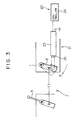
- Fig. 1 shows a drive control system for a hydraulic construction machine, according to a first embodiment of the invention.
- the drive control system comprises a prime mover or an engine 1, a hydraulic pump 2 driven by the engine 1, and a hydraulic actuator 3 driven by discharge hydraulic fluid from the hydraulic pump 2.
- a control valve 4 is connected between the hydraulic pump 2 and the hydraulic actuator 3, for controlling flow rate and direction of the hydraulic fluid supplied from the hydraulic pump 2 to the hydraulic actuator 3.
- the system comprises a plurality of actuators 3 and control valve 4.
- the prime mover 1 is preferably a diesel engine which comprises a fuel injection system provided with an all-speed governor.
- a first rotational speed setting device 7 is provided, which is composed of a first operating device or a fuel lever 5, and a governor lever 6 operatively connected to the fuel lever 5.
- the governor lever is operated in a direction B in response to the operation of tie fuel lever 5, so that the rotational speed is set to a value in compliance with displacement of the fuel lever 5.
- the operation of the hydraulic actuators 3 is controlled by a respective second operating device 8.
- the second operating device 8 comprises an operating lever 9 and two hydraulic pilot valves 10 and 11.
- the hydraulic pilot valves 10 and 11 have their respective primary ports which are connected to a pilot pump 12 driven by the engine 1 and to a reservoir 13. Second ports of the respective hydraulic pilot valves 10 and 11 are connected respectively to pilot ports of the control valve 4 through respective pilot lines 14 and 15.
- the arrangement is such that the pilot valves 10 and 11 are supplied with primary pressure from the pilot pump 12, and secondary pressures in accordance with displacements of the respective pilot valves 10 and 11 are supplied respectively to the pilot ports of the control valve 4.
- the control valve 4 is controlled in position, that is, in stroke amount and direction, thereby controlling the flow rate and the direction of the hydraulic fluid supplied to the hydraulic actuator 3 to control the operation of the same.
- the second operating device 8 is also provided with springs 16 and 17 which serve to increase lever operating force when displacement of the operating lever 9, that is, an operating amount thereof exceeds a predetermined value X0.
- springs 16 and 17 serve to increase lever operating force when displacement of the operating lever 9, that is, an operating amount thereof exceeds a predetermined value X0.
- the second operating devices 8 are respectively connected to a second rotational speed setting device 20 which outputs a rotational speed control signal increasing the set rotational speed of the engine 1 as the sum of displacements of the operating devices exceeds the predetermined value X0.
- a rotational speed control device 21 is associated with the second rotational speed setting device 20.
- the second rotational speed setting device 20 is composed of a plurality of pressure sensors 23 connected to the pilot lines 14 and 15 of the respective actuator through a shuttle valve 22, for detecting the maximum pressure, and a controller 24 formed by a microcomputer or the like.
- a detecting signal from the sensors 23 is inputted into the controller 24, and the controller 24 executes a predetermined operation processing to obtain the above-mentioned rotational control signal and outputs the same.
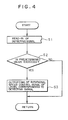
- the controller has inputted beforehand therein a control program as shown by a flow chart in Fig. 4, inclusive of the above predetermined value X0.
- the rotational speed control device 21 is comprised, for example, of a linear solenoid cylinder 25 which is adapted to extend a piston 26 in accordance with a level of tie rotational control signal from the controller 24, to operate the governor lever 6 in the direction B.
- the detecting signals from the pressure sensors 23 are read into the controller 24 at a step S1.
- a step S2 it is judged by the controller 24 wheter or not the sum of displacements of the operating levers 9 indicated by the detecting signals exceeds the above-mentioned predetermined value X0 which is set beforehand. If it is not judged that the sum of displacement exceeds the predetermined value X0, the program skips a step S3 and is returned to the start (step S1). Accordingly, the rotational speed control signal is not outputted from the controller 24, and the linear solenoid cylinder 25 shown in Fig. 3 is not actuated. Thus, the governor lever 6 is operated only of the fuel lever 5, so that the rotational speed set by the fuel lever 5 is validated.
- the program proceeds to the step S3 where the rotational speed control signal of a level corresponding to the read-in detecting signal is outputted.
- This rotational speed control signal is sent to the linear solenoid cylinder 25, to proportionally control the stroke amount of the piston 26.
- the governor lever 6 is operated by the linear solenoid cylinder 25, so that the rotational speed set by the controller 24 is set.
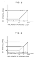
- the rotational speed control device 21 is so arranged as to adjust the rotational speed set by the first rotational speed setting device 7 in a first region Z1 in which the sum of displacements of the second operating devices 8 is at least equal to or less than the above predetermined value X0, that is, is equal to or less than the predetermined value X0 or the sun of displacements X1 larger than the predetermined value.
- the rotational speed control device 21 sets a rotational speed higher than the rotational speed set by the first rotational speed setting device 7, modified by the rotational speed control signal from the second rotational speed setting device 20 in a second region Z2 in which the sum of displacements is larger than the value X0 or X1.
- the rotational speed control device 21 is so arranged as to adjust the set rotational speed indicated by the rotational speed control signal from the second rotational speed setting device 21 in the second region Z2.
- Fig. 7 is a graphical representation of one operational cycle which is a typical example of the operation conducted by the hydraulic excavator, in which 1 excavating, 2 boom raising-swing, 3 dumping and 4 boom lowering-swing are repeated in the mentioned order.
- Fig. 7 shows the one operational cycle in relation to the engine output power required for each operation.
- N A is a set rotational speed of the engine suitable for giving the output power required for the light load operation
- N B is a set rotational speed suitable for giving the output power required for the usual heavy load operation
- N C is a set rotational speed suitable for giving the output power required for especially heavy load operation.
- Fig. 8 shows an output horsepower characteristic, a torque characteristic and a specific fuel consumption when the engine rotational speed is set to a selected one of the above values N A , N B and N C .
- the specific fuel consumption is brought to a value g 1c and is excellent, at the relief excavation of the operation 1 and at acceleration at the initial stage of the swing in the operation 2, as shown in the operation 2, as shown in Fig. 8.
- the specific fuel consumption is brought to a value g 2c
- the specific fuel consumption is brought to a value g 3c .
- the specific fuel consumption is deteriorated.
- the specific fuel consumption is raised, for example, to g2 b and g 3g .
- the engine rotational speed frequently fluctuates in interlocked relation to operation of the operating lever, during almost all of the period of time of the operations other than the boom Iowering-swing operation, so that energy is consumed to accelerate the flywheel of the engine. This is not preferable in the specific fuel consumption.
- the rotational speed is set to a value of a desirable level in dependence upon displacement of the fuel level 5 in the first region Z1.
- the engine rotational speed is set to the value N B by the fuel lever 5, whereby the specific fuel consumption in the vicinity of g 2b , is obtained at the usual excavating of 1 and at the usual swing of 2, and the specific fuel consumption in the vicinity of g 3b more excellent than g 3c is obtained at the dumping of 3 and at the boom lowering-swing of 4.
- the rotational speed is set to the higher value by the operating levers 9, the rotational speed of the engine is set by operation of the operating levers 9 at the relief excavating of 1 and at acceleration at the initial stage of the swing of 2, to obtain a higher set rotational speed, whereby the specific fuel consumption of g 1c is obtained. In this manner, it is possible to obtain excellent specific fuel consumption as a whole.
- the above-mentioned predetermined value X0 is determined in consideration of the following points.
- the first point is as follows.
- the engine rotational speed is set by the fuel lever 5 to a value in the vicinity of the idling N i which is employed in the lightest load operation such as normal plane operation or the like
- the discharge quantity of the hydraulic pump 2 is determined by the rotational speed.
- the control valve 4 begins to be opened in dependence upon displacement of tie operating lever, and the requisite flow rate required by the control valve and the flow rate of fluid passing through the control valve flowing at the discharge quantity of the hydraulic pump are brought into coincidence with each other at a certain specific opening degree of the control valve.
- the first point is to bring the sum of displacements of the operating lever 9 indicating the specific opening degree to X0.
- the sun of displacements of the operating levers 9 is brought to a value obtaining the opening degree of the control valves 4 at which the flow rate of fluid passing through the control valves 4 obtained by restricting the discharge quantity of the hydraulic pump 2 is brought into coincidence with the requisite flow rate.
- the engine rotational speed can be set in interlocked relation to the operating levers in a region equal to or higher than the predetermined value X0 or X1.
- the second point is the sum of displacements of the operating levers 9 which obtains a valve opening degree corresponding to an upper limit of a metering region of the control valve 4 required for the fine or minute operation working.
- the sum of displacements of the operating levers 9 and the set rotational speed of the engine are brought to the linear proportional relationship in the second region Z2 as shown in Figs. 5 and 6, but are not limited only to this relationship.
- the arrangement may be such that the opening degree of the control valve 4 is calculated on the basis of the sum of displacements of the operating levers 9, and an engine rotational speed control signal is outputted which can obtain discharge quantity of the hydraulic pump 2 corresponding to the requisite flow rate prescribed by the opening degree.
- the engine rotational speed increases in predetermined functional relation other than the linear proportion to the displacements of the operating levers.
- the rotational speed control signal outputted from the controller 24 is increased proportionally in dependence upon sum of displacements of the operating levers 9, and the linear solenoid cylinder 25 is employed which is operated with a strove amount on the oasis of the signal.
- the predetermined value forming the boundary between tee first and second regions Z1 and Z2 is changed from X0 to X1 in dependence upon the rotational speed set by the fuel lever 5, and the set rotational speed increases in response to sum of displacements of the operating levers 9 in the second region Z2.
- an arrangement different from the above embodiment in this respect can be employed.
- a rotational speed control device 32 may be composed of an electromagnetic directional control valve 30 turned on and off in response to the rotational speed control signal, and a hydraulic cylinder 31 movable between ON and OFF positions in accordance with the position of the directional control valve 30.
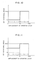
- the relationship between the sum of displacement of the operating levers 9 and the set rotational speed of the engine is brought to one as shown in Fig. 10 of the rotational speed set by the fuel lever 5 is the idling N i , and to one as shown in Fig. 11 if the rotational speed set by the fuel lever 5 is the intermediate rotational speed N1. That is, the predetermined value forming the boundary between the first and second regions Z1 and Z2 is X0 and is constant independently of the rotational speed set by the fuel lever 5, while the set rotational speed is brought to the maximum value N max in the second region Z2 independently of displacement of the operating lever 9. With such arrangement, the number of component parts is reduced and the structure is simplified.
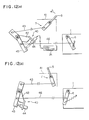
- FIGs. 12(a) through 12(c) shows an embodiment having such arrangement, in which the reference numeral 40 denotes a rotational speed control device.
- the rotational speed control device 40 is so arranged as to add the rotational speed set by the rotational speed control signal to the set rotational speed obtained by the fuel lever 5 in the above-mentioned second region Z2.
- the fuel lever 5 is pivotally supported by a console box 41 within an operator's cab, and is connected, through a push-pull cable 43, to one end of a first intermediate lever 42 which is pivotally supported at a predetermined portion of the vehicle.
- the first intermediate lever 42 has the other end to which a linear solenoid cylinder 44 is fixedly mounted.
- a second intermediate lever 45 is pivotally supported in coaxial relation to the first intermediate lever 42. Pivotal movement of the first intermediate lever 42 is transmitted to the second intermediate lever 45 through the linear solenoid cylinder 44.
- the second intermediate lever 45 is connected to the governor lever 6 through a push-pull cable 46.
- the rotational speed control signal is supplied from the controller 24 of the second control setting means 20 to the linear solenoid cylinder 44, so that a stroke amount corresponding to the magnitude of the signal is obtained at the linear solenoid cylinder 44.
- An idling position is a position where pivotal movement of the fuel lever 5 in the direction A causes the forward end of the linear solenoid cylinder 25 to be brought into engagement with the second intermediate lever 45.
- the set rotational speed of the engine 1 is a constant value N i in the first region Z1 of from zero to the predetermined value X0 of the sum of displacements of the operating levers 9.
- a rotational speed control value increasing in proportion to the displacement is obtained at the second rotational speed setting device 20.
- a rotational speed control signal corresponding to the rotational speed control valve is sent to the linear solenoid cylinder 44, so that the linear solenoid cylinder 44 extends with a stroke in dependence upon the rotational speed control signal.
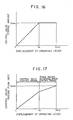
- the set rotational speed increases in the second region Z2 as indicated by the line 11 in Fig. 13.
- the linear solenoid cylinder 44 may be formed by an actuator operable between ON and OFF positions. In this case, the relationship of the set rotational speed of the engine with respect to the sum of displacement of the operating levers 9 is brought to one shown in Fig. 14.
- Fig. 15 shows an embodiment having such arrangement.
- component parts similar to those illustrated in Fig. 1 are designated by the same reference numerals.
- a second rotational speed setting device 60 comprises a directional control valve 61 which is controlled in switching as the secondary pressure of the operating device 8 formed by a pilot valve exceeds a predetermined value corresponding to the predetermined value X0 of the sum of displacement of the operating levers 9, and a rotational speed control device 62 comprises a proportional control hydraulic cylinder 63 which is extended and retracted directly by the secondary pressure of the operating device 8 transmitted through the directional control valve 61. That is, when the secondary pressure of the operating device 8 is equal to or lower than the predetermined value, the directional control valve 61 is in the illustrated position where transmission of the secondary pressure is blocked.
- the directional control valve 61 is switched to the other position where the secondary pressure is applied to the hydraulic cylinder 63 as a rotational speed control signal, so that the hydraulic cylinder 63 is extended with a stroke amount corresponding to the pressure.
- the relationship between the sum of displacements of the operating levers 9 and the set rotational speed of the engine 1 is brought to one shown in Figs. 5 and 6 in dependence upon the rotational speed set by the fuel lever 5.
- the hydraulic cylinder 63 is controlled in an ON and OFF manner, the relationship between the aforesaid displacement and the set rotational speed is brought to one shown in Figs. 10 and 11.
- the arrangement illustrated in Figs. 12(a) through 12(c) is employed so as to add the value set by the second rotational speed setting device 60, the relationship between displacement of the operating lever and the set rotational speed is brought to one shown in Fig. 13.
- control is carried out in an ON and OFF manner, the relationship is brought to one shown in Fig. 14.
- the relationship between the sum of displacement of the operating levers 9 and the stroke amount determining the opening degree of the control valve 4 is set such that, the stroke amount of the control valve is so set as not to reach the maximum value when the displacement of the operating lever reaches the predetermined value X0, but as to be brought to an intermediate stroke amount.
- setting can be made such that the stroke amount of the control valve 4 is brought to the maximum value (maximum in opening degree), when the operating levers 9 together are operated up to the predetermined value X0.
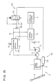
- the arrangement of this embodiment is such that a hydraulic pump 90 of variable capacity type is employed, and a displacement volume of the hydraulic pump is varied by a displacement volume control device 91 which regulates an angle of inclination of a swash plate of the hydraulic pump.
- a controller 92 forms a second rotational speed setting device 93 for outputting a rotational speed control signal to the rotational speed control device 21.
- the controller 92 also outputs a displacement volume control signal to the displacement volume control device 91.
- the controller 92 has stored therein a control program as indicated by a flow chart in Fig. 19.
- a detecting signal from the pressure sensor 23 is read into the controller 92. It is judged at a step S2 whether or not the sum indicated by the detecting signals exceeds the predetermined value X0. If it is judged that the sum exceeds the predetermined value, the rotational speed control signal increasing the set rotational speed of the engine 1 in proportion to the displacement is outputted at a step S3.
- the displacement volume control signal reducing the displacement volume (angle of inclination) in dependence upon the increase in the set rotational speed is outputted to the displacement volume control device 91.
- the displacement volume control signal is so determined as to reduce the displacement volume such that the discharge quantity of the hydraulic pump is brought substantially to a constant value with respect to the increase in the engine rotational speed.
- the arrangement of the present embodiment is such that the stroke amount of the control valve 4 is brought to the maximum value, that is, the valve opening degree is brought to the maximum value, at the predetermined value X0 of the sum of operating lever displacement.
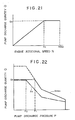
- the discharge quantity of the hydraulic pump 90 increases in proportion to an increase in the engine rotational speed until the engine rotational speed reaches a value N0 corresponding to the predetermined value X0 of the operating lever displacement, because the displacement volume is constant.
- the discharge quantity is brought to a constant value Q0 until the discharge quantity reaches the maximum value N max as described above.
- the relationship between the pump discharge pressure P and the pump discharge quantity Q at this time is brought to one shown in Fig. 22.
- the relationship indicates a P-Q characteristic as shown by the dot-and-chain line in the running condition of the rotational speed N0, and indicates a P-Q characteristic as shown by the solid line in the running condition of the rotational speed N max .
- the P-Q characteristic varies continuously between the dot-and-chain line and the solid line in response to variation in the rotational speed.
- the region in which tie pump discharge quantity Q is constant at Q0 increases from P0 to P1 of tie pump pressure, and the absorption horsepower also increase correspondingly.
- the P-Q characteristic is brought to one indicated by the broken line in Fig. 22 at N max of the engine rotational speed.
- the pump discharge quantity Q0 is controlled to a constant value in the range equal to or higher than the engine rotational speed N0, it is made possible to increase the consumptive horsepower correspondingly to an increase in tie engine rotational speed.
- the engine horsepower can effectively be utilized while the operating speed is maintained constant.
- the control valve 4 is maintained at the maximum opening degree like the present embodiment, the entire pump discharge quantity can be supplied to the hydraulic actuator 3, whereby it is made possible to more effectively utilize the engine horsepower.
- the displacement volume control device 91 may be composed, for example, of a hydraulic cylinder and a linear solenoid valve proportionally controlled by the signal from the controller 92.
- Fig. 23 shows an embodiment having such arrangement, in which component parts similar to those shown in Fig. 18 are designated by the same reference numerals. That is, a controller 95 has inputted thereinto a signal from the displacement detector 73 for detecting displacement of the fuel lever 5, and signals from the respective detecting devices 75 and 76 for detecting displacements of the respective operating levers 9 and 72. The controller 75 outputs a commmand signal instructing a final set rotational speed to the pulse motor 77, and outputs a displacement volume control signal to a displacement volume control device 96 formed by a linear solenoid cylinder.
Landscapes
- Engineering & Computer Science (AREA)
- General Engineering & Computer Science (AREA)
- Mining & Mineral Resources (AREA)
- Civil Engineering (AREA)
- Structural Engineering (AREA)
- Chemical & Material Sciences (AREA)
- Combustion & Propulsion (AREA)
- Mechanical Engineering (AREA)
- Control Of Vehicle Engines Or Engines For Specific Uses (AREA)
- Operation Control Of Excavators (AREA)
- Fluid-Pressure Circuits (AREA)
Applications Claiming Priority (2)
| Application Number | Priority Date | Filing Date | Title |
|---|---|---|---|
| JP23667686 | 1986-10-05 | ||
| JP236676/86 | 1986-10-05 |
Publications (3)
| Publication Number | Publication Date |
|---|---|
| EP0287670A1 EP0287670A1 (en) | 1988-10-26 |
| EP0287670A4 EP0287670A4 (en) | 1988-12-15 |
| EP0287670B1 true EP0287670B1 (en) | 1991-08-07 |
Family
ID=17004132
Family Applications (1)
| Application Number | Title | Priority Date | Filing Date |
|---|---|---|---|
| EP87906462A Expired - Lifetime EP0287670B1 (en) | 1986-10-05 | 1987-10-02 | Driving control apparatus for hydraulic construction machines |
Country Status (7)
| Country | Link |
|---|---|
| US (1) | US4942737A (ko) |
| EP (1) | EP0287670B1 (ko) |
| JP (1) | JP2619882B2 (ko) |
| KR (1) | KR920001170B1 (ko) |
| CN (1) | CN1012513B (ko) |
| DE (1) | DE3772042D1 (ko) |
| WO (1) | WO1988002441A1 (ko) |
Families Citing this family (28)
| Publication number | Priority date | Publication date | Assignee | Title |
|---|---|---|---|---|
| JP2831377B2 (ja) * | 1988-07-04 | 1998-12-02 | 日立建機株式会社 | 建設機械の原動機回転数制御装置 |
| JPH02107802A (ja) * | 1988-08-31 | 1990-04-19 | Hitachi Constr Mach Co Ltd | 油圧駆動装置 |
| JPH07103593B2 (ja) * | 1990-06-06 | 1995-11-08 | 株式会社小松製作所 | 積み込み作業車両の制御装置及び方法 |
| US5138838A (en) * | 1991-02-15 | 1992-08-18 | Caterpillar Inc. | Hydraulic circuit and control system therefor |
| US5286171A (en) * | 1991-11-13 | 1994-02-15 | Shin Caterpillar Mitsubishi Ltd. | Method for controlling engine for driving hydraulic pump to operate hydraulic actuator for construction equipment |
| JP2603749Y2 (ja) * | 1992-02-28 | 2000-03-21 | 株式会社タダノ | 車両搭載型クレーンにおけるエンジンアクセルの制御装置 |
| JP2992434B2 (ja) * | 1993-12-02 | 1999-12-20 | 日立建機株式会社 | 建設機械の油圧制御装置 |
| US5525043A (en) * | 1993-12-23 | 1996-06-11 | Caterpillar Inc. | Hydraulic power control system |
| US5468126A (en) * | 1993-12-23 | 1995-11-21 | Caterpillar Inc. | Hydraulic power control system |
| WO1995030059A1 (fr) * | 1994-04-28 | 1995-11-09 | Hitachi Construction Machinery Co., Ltd. | Dispositif de commande d'excavation a limitation de surface de travail pour engin de terrassement |
| US5967756A (en) * | 1997-07-01 | 1999-10-19 | Caterpillar Inc. | Power management control system for a hydraulic work machine |
| JP3660501B2 (ja) * | 1998-05-28 | 2005-06-15 | 日立建機株式会社 | 建設機械のエンジン回転数制御装置 |
| US6799649B2 (en) * | 1999-03-15 | 2004-10-05 | Deka Products Limited Partnership | Control of a balancing personal vehicle |
| CA2366076C (en) * | 1999-03-15 | 2009-11-17 | Deka Products Limited Partnership | Control of a balancing personal vehicle |
| JP4475767B2 (ja) * | 2000-08-03 | 2010-06-09 | 株式会社小松製作所 | 作業用車両 |
| US6498973B2 (en) * | 2000-12-28 | 2002-12-24 | Case Corporation | Flow control for electro-hydraulic systems |
| JP4484467B2 (ja) * | 2003-08-01 | 2010-06-16 | 日立建機株式会社 | 走行式油圧作業機 |
| US7040044B2 (en) * | 2003-12-15 | 2006-05-09 | Caterpillar S.A.R.L. | Method of modulating a boom assembly to perform in a linear manner |
| JP5125048B2 (ja) * | 2006-09-29 | 2013-01-23 | コベルコ建機株式会社 | 作業機械の旋回制御装置 |
| US7748279B2 (en) * | 2007-09-28 | 2010-07-06 | Caterpillar Inc | Hydraulics management for bounded implements |
| US7832208B2 (en) * | 2007-11-13 | 2010-11-16 | Caterpillar Inc | Process for electro-hydraulic circuits and systems involving excavator boom-swing power management |
| DE102007062888A1 (de) * | 2007-12-28 | 2009-07-02 | Robert Bosch Gmbh | Verfahren zum Steuern eines hydrostatischen Antriebs |
| JP2009214599A (ja) * | 2008-03-07 | 2009-09-24 | San Max Kk | 作業用車両 |
| SE532428C2 (sv) * | 2008-05-29 | 2010-01-19 | Scania Cv Abp | Metod för reglering av en motors varvtal |
| US8689471B2 (en) * | 2012-06-19 | 2014-04-08 | Caterpillar Trimble Control Technologies Llc | Method and system for controlling an excavator |
| CN102767204B (zh) * | 2012-07-27 | 2015-02-18 | 中联重科股份有限公司渭南分公司 | 暖机控制设备、控制系统和控制方法及工程机械设备 |
| KR101744709B1 (ko) * | 2013-03-25 | 2017-06-08 | 히다치 겡키 가부시키 가이샤 | 작업 기계의 엔진 회전수 제어 장치 |
| JP6342933B2 (ja) * | 2016-03-14 | 2018-06-13 | 株式会社タダノ | 操作レバー |
Citations (2)
| Publication number | Priority date | Publication date | Assignee | Title |
|---|---|---|---|---|
| JPS58204940A (ja) * | 1982-05-24 | 1983-11-29 | Hitachi Constr Mach Co Ltd | エンジンの燃料噴射ポンプ制御装置 |
| JPS6111429A (ja) * | 1984-06-26 | 1986-01-18 | Hitachi Constr Mach Co Ltd | 原動機と油圧ポンプを含む系の制御装置 |
Family Cites Families (13)
| Publication number | Priority date | Publication date | Assignee | Title |
|---|---|---|---|---|
| JPS4853162A (ko) * | 1971-11-04 | 1973-07-26 | ||
| JPS5517241B2 (ko) * | 1972-07-28 | 1980-05-10 | ||
| JPS5015980A (ko) * | 1973-06-15 | 1975-02-20 | ||
| JPS52189A (en) * | 1975-06-23 | 1977-01-05 | Tech Res & Dev Inst Of Japan Def Agency | Radiowave type proximity fuse |
| JPS52106526A (en) * | 1976-03-04 | 1977-09-07 | Nissan Motor Co Ltd | Apparatus to increase folk lift loading speed |
| GB1527957A (en) * | 1977-03-22 | 1978-10-11 | Towmotor Corp | Motor control |
| GB2064073B (en) * | 1979-11-23 | 1984-02-15 | Linde Ag | Conjoint control of engine and infinitely variable transmission |
| US4373850A (en) * | 1980-02-14 | 1983-02-15 | Durham M E | Automatic fuel control system |
| JPS59129957A (ja) * | 1983-01-13 | 1984-07-26 | Matsushita Electric Ind Co Ltd | 磁気記録再生装置 |
| JPS6038561A (ja) * | 1983-08-11 | 1985-02-28 | ダイキン工業株式会社 | 複合ヒ−トポンプ加熱装置 |
| JPH066476B2 (ja) * | 1984-11-21 | 1994-01-26 | 古河機械金属株式会社 | 油圧式クレーンの速度制御方法 |
| JP2566751B2 (ja) * | 1985-02-28 | 1996-12-25 | 株式会社小松製作所 | エンジン駆動の可変容量型油圧ポンプの出力制御方法 |
| US4738104A (en) * | 1985-03-23 | 1988-04-19 | Barmag Ag | Hydraulic power system |
-
1987
- 1987-10-02 EP EP87906462A patent/EP0287670B1/en not_active Expired - Lifetime
- 1987-10-02 DE DE8787906462T patent/DE3772042D1/de not_active Expired - Lifetime
- 1987-10-02 WO PCT/JP1987/000737 patent/WO1988002441A1/ja active IP Right Grant
- 1987-10-02 US US07/205,321 patent/US4942737A/en not_active Expired - Lifetime
- 1987-10-02 KR KR1019880700632A patent/KR920001170B1/ko not_active IP Right Cessation
- 1987-10-02 JP JP62249150A patent/JP2619882B2/ja not_active Expired - Fee Related
- 1987-10-05 CN CN87106788A patent/CN1012513B/zh not_active Expired
Patent Citations (2)
| Publication number | Priority date | Publication date | Assignee | Title |
|---|---|---|---|---|
| JPS58204940A (ja) * | 1982-05-24 | 1983-11-29 | Hitachi Constr Mach Co Ltd | エンジンの燃料噴射ポンプ制御装置 |
| JPS6111429A (ja) * | 1984-06-26 | 1986-01-18 | Hitachi Constr Mach Co Ltd | 原動機と油圧ポンプを含む系の制御装置 |
Also Published As
| Publication number | Publication date |
|---|---|
| WO1988002441A1 (en) | 1988-04-07 |
| JPS63239327A (ja) | 1988-10-05 |
| EP0287670A4 (en) | 1988-12-15 |
| CN1012513B (zh) | 1991-05-01 |
| KR880701818A (ko) | 1988-11-05 |
| EP0287670A1 (en) | 1988-10-26 |
| JP2619882B2 (ja) | 1997-06-11 |
| DE3772042D1 (de) | 1991-09-12 |
| CN87106788A (zh) | 1988-08-10 |
| KR920001170B1 (ko) | 1992-02-06 |
| US4942737A (en) | 1990-07-24 |
Similar Documents
| Publication | Publication Date | Title |
|---|---|---|
| EP0287670B1 (en) | Driving control apparatus for hydraulic construction machines | |
| EP1655469B1 (en) | Control device for working vehicle | |
| EP0765970B1 (en) | Hydraulic control apparatus for hydraulic construction machine | |
| EP0214633B1 (en) | Control system for hydraulically-operated construction machinery | |
| KR101069473B1 (ko) | 주행 작업 차량의 제어 장치 | |
| KR100801930B1 (ko) | 작업차량의 엔진의 부하 제어장치 | |
| EP0884422B1 (en) | Engine control system for construction machine | |
| US7469535B2 (en) | Hydraulic driving control device and hydraulic shovel with the control device | |
| US5295353A (en) | Controlling arrangement for travelling work vehicle | |
| KR100279041B1 (ko) | 유압건설기계의 원동기의 오토 액셀러레이터장치 및 원동기와유압펌프의 제어장치 | |
| KR20070046853A (ko) | 작업차량의 엔진의 부하제어장치 | |
| WO2013145339A1 (ja) | 作業車両及び作業車両の制御方法 | |
| JP3316053B2 (ja) | 油圧建設機械の原動機回転数制御装置 | |
| WO2013145342A1 (ja) | ホイールローダ及びホイールローダの制御方法 | |
| KR100805990B1 (ko) | 유압구동제어장치 | |
| JP4127771B2 (ja) | 建設機械のエンジン制御装置 | |
| JP4121687B2 (ja) | 油圧走行車両 | |
| EP3865628B1 (en) | Control method for construction machinery and control system for construction machinery | |
| JPS63241226A (ja) | ホイ−ル式油圧シヨベルの油圧制御装置 | |
| JPH0635873B2 (ja) | 建設機械の油圧制御装置 | |
| JP2866178B2 (ja) | 作業車両の油圧駆動装置 | |
| KR20080049519A (ko) | 중장비의 엔진 제어장치 | |
| JPH02279837A (ja) | 油圧式建設機械の原動機回転数制御装置 |
Legal Events
| Date | Code | Title | Description |
|---|---|---|---|
| PUAI | Public reference made under article 153(3) epc to a published international application that has entered the european phase |
Free format text: ORIGINAL CODE: 0009012 |
|
| 17P | Request for examination filed |
Effective date: 19880527 |
|
| AK | Designated contracting states |
Kind code of ref document: A1 Designated state(s): DE FR GB IT |
|
| A4 | Supplementary search report drawn up and despatched |
Effective date: 19881215 |
|
| 17Q | First examination report despatched |
Effective date: 19900112 |
|
| GRAA | (expected) grant |
Free format text: ORIGINAL CODE: 0009210 |
|
| AK | Designated contracting states |
Kind code of ref document: B1 Designated state(s): DE FR GB IT |
|
| ITF | It: translation for a ep patent filed |
Owner name: JACOBACCI & PERANI S.P.A. |
|
| ET | Fr: translation filed | ||
| REF | Corresponds to: |
Ref document number: 3772042 Country of ref document: DE Date of ref document: 19910912 |
|
| PLBE | No opposition filed within time limit |
Free format text: ORIGINAL CODE: 0009261 |
|
| STAA | Information on the status of an ep patent application or granted ep patent |
Free format text: STATUS: NO OPPOSITION FILED WITHIN TIME LIMIT |
|
| 26N | No opposition filed | ||
| PGFP | Annual fee paid to national office [announced via postgrant information from national office to epo] |
Ref country code: FR Payment date: 19940818 Year of fee payment: 8 |
|
| PG25 | Lapsed in a contracting state [announced via postgrant information from national office to epo] |
Ref country code: FR Effective date: 19960628 |
|
| REG | Reference to a national code |
Ref country code: FR Ref legal event code: ST |
|
| REG | Reference to a national code |
Ref country code: GB Ref legal event code: IF02 |
|
| PGFP | Annual fee paid to national office [announced via postgrant information from national office to epo] |
Ref country code: GB Payment date: 20060927 Year of fee payment: 20 |
|
| PGFP | Annual fee paid to national office [announced via postgrant information from national office to epo] |
Ref country code: DE Payment date: 20060928 Year of fee payment: 20 |
|
| PGFP | Annual fee paid to national office [announced via postgrant information from national office to epo] |
Ref country code: IT Payment date: 20061031 Year of fee payment: 20 |
|
| REG | Reference to a national code |
Ref country code: GB Ref legal event code: PE20 |
|
| PG25 | Lapsed in a contracting state [announced via postgrant information from national office to epo] |
Ref country code: GB Free format text: LAPSE BECAUSE OF EXPIRATION OF PROTECTION Effective date: 20071001 |