EP0287670A1 - Driving control apparatus for hydraulic construction machines - Google Patents
Driving control apparatus for hydraulic construction machines Download PDFInfo
- Publication number
- EP0287670A1 EP0287670A1 EP87906462A EP87906462A EP0287670A1 EP 0287670 A1 EP0287670 A1 EP 0287670A1 EP 87906462 A EP87906462 A EP 87906462A EP 87906462 A EP87906462 A EP 87906462A EP 0287670 A1 EP0287670 A1 EP 0287670A1
- Authority
- EP
- European Patent Office
- Prior art keywords
- rotational speed
- displacement
- hydraulic
- operating
- operating means
- Prior art date
- Legal status (The legal status is an assumption and is not a legal conclusion. Google has not performed a legal analysis and makes no representation as to the accuracy of the status listed.)
- Granted
Links
Images


Classifications
-
- E—FIXED CONSTRUCTIONS
- E02—HYDRAULIC ENGINEERING; FOUNDATIONS; SOIL SHIFTING
- E02F—DREDGING; SOIL-SHIFTING
- E02F9/00—Component parts of dredgers or soil-shifting machines, not restricted to one of the kinds covered by groups E02F3/00 - E02F7/00
- E02F9/20—Drives; Control devices
- E02F9/22—Hydraulic or pneumatic drives
- E02F9/2246—Control of prime movers, e.g. depending on the hydraulic load of work tools
-
- E—FIXED CONSTRUCTIONS
- E02—HYDRAULIC ENGINEERING; FOUNDATIONS; SOIL SHIFTING
- E02F—DREDGING; SOIL-SHIFTING
- E02F9/00—Component parts of dredgers or soil-shifting machines, not restricted to one of the kinds covered by groups E02F3/00 - E02F7/00
- E02F9/20—Drives; Control devices
- E02F9/22—Hydraulic or pneumatic drives
- E02F9/2278—Hydraulic circuits
- E02F9/2296—Systems with a variable displacement pump
-
- F—MECHANICAL ENGINEERING; LIGHTING; HEATING; WEAPONS; BLASTING
- F02—COMBUSTION ENGINES; HOT-GAS OR COMBUSTION-PRODUCT ENGINE PLANTS
- F02D—CONTROLLING COMBUSTION ENGINES
- F02D29/00—Controlling engines, such controlling being peculiar to the devices driven thereby, the devices being other than parts or accessories essential to engine operation, e.g. controlling of engines by signals external thereto
- F02D29/04—Controlling engines, such controlling being peculiar to the devices driven thereby, the devices being other than parts or accessories essential to engine operation, e.g. controlling of engines by signals external thereto peculiar to engines driving pumps
Definitions
- the present invention relates to a drive control system for hydraulic construction machines represented by a hydraulic excavator, a wheel loader and the like and, particularly, to a drive control system for a hydraulic construction machine, which comprises a prime mover and a hydraulic pump driven thereby.
- a conventional drive control system for a hydraulic construction machine comprises a prime mover, a hydraulic pump driven by the prime mover, a hydraulic actuator driven by discharge hydraulic fluid from the hydraulic pump, rotational speed setting means including a fuel lever for setting rotational speed of the prime mover, and an operating lever for controlling operation of the hydraulic actuator.
- rotational speed setting means including a fuel lever for setting rotational speed of the prime mover, and an operating lever for controlling operation of the hydraulic actuator.
- Connected between the hydraulic pump and the hydraulic actuator is a control valve for controlling flow rate and direction of the discharge hydraulic fluid from the hydraulic pump. Operation of the operating lever controls the position of the control valve to control operation of the hydraulic actuator.
- rotational speed of the prime mover or an engine is set by displacement of the fuel lever, to vary a horsepower characteristic of the engine in accordance with the set rotational speed.
- the maximum horsepower of the engine is determined on the basis of the horsepower characteristic.
- Specific fuel consumption (g/PS.h) of the engine is determined depending upon the set rotational speed and the magnitude of an operational load at that time. If, for example, the rotational speed is set to the maximum value, the specific fuel consumption is brought to the best value, at the heavy load operation in the vicinity of the maximum horsepower of the horsepower characteristic obtained by the set rotational speed.
- the engine rotational speed increases to a value higher than the rotational speed at the maximum horsepower of the horsepower characteristic, so that the specific fuel consumption is deteriorated.
- the proportion of the operation which is carried out under the load excellent in the specific fuel consumption is extremely low.
- the operations necessitating the above-mentioned maximum horsepower are only the relief excavating during the operation 1 and the operation at acceleration at the initial stage of the swing during the operation 2.
- Japanese Patent Application Laid-Open No. 52-53189 has proposed an arrangement in which not only is the rotational speed of the engine set by the fuel lever, but also the engine rotational speed is interlocked with the operating lever for controlling operation of the hydraulic actuator in such a manner that when the operating lever is operated, the engine rotational speed is set also by displacement of the operating lever, to vary the horsepower characteristic, thereby controlling the maximum horsepower.
- the engine rotational speed is set to a low value to give the maximum horsepower required for the light load operation
- the engine rotational speed is set to a high value to raise also the maximum horsepower of the engine so as to give the maximum horsepower required for the heavy load operation.
- Japanese Patent Application Laid-Open No. 58-204940 has proposed an arrangement in which only a specific operating lever is interlocked with the engine rotational speed, and only when the operating lever is operated, the engine rotational speed is set by displacement of the operating lever to vary the horsepower characteristic, thereby controlling the maximum horsepower.
- low rotational speed providing the maximum horsepower required for the light load operation is set by the fuel lever and, usually, the operation is carried out with the horsepower characteristic obtained at the low set rotational speed.
- the rotational speed is set, in interlocked relation to the operation of the operating lever, to a value higher than that set by the fuel lever, so as to give the maximum horsepower required for the heavy load operation with the horsepower characteristic obtained at the set rotational speed, like the above-described conventional system.
- the operation is carried out always in a region excellent in the specific fuel consumption, thereby preventing deterioration of the specific fuel consumption.
- Japanese Patent Application No. 59-129957 has proposed an arrangement comprising, in place of the control valve, a hydraulic pump of variable capacity type and means for varying an angular position of a swash plate of the hydraulic pump, that is, a displacement volume of the hydraulic pump by the operating lever, wherein the engine rotational speed is controlled only by the operating lever, the engine rotational speed is set to a low value when displacement of the operating lever is equal to or lower than a predetermined value, and as the displacement of the operating lever exceeds the predetermined value, the rotational speed is set to a high value in dependence upon the displacement of the operating lever, also in this system, like the above-mentioned conventional system, an attempt can be made to improve the specific fuel consumption, because, in the displacement of the operating lever equal to or larger than the predetermined value, the engine rotational speed is set on the basis of the displacement of the operating lever.
- Japanese Patent Application Laid-Open Nos. 48-53162 and 50-15980, and Japanese Patent Publication No. 60-38561 are listed as being relevant to the arrangement in which the engine rotational speed is interlocked with operation of the operating lever.
- U.S. Patent Serial No. 947,524 (corresponding to EPC Application No. 86118113.9) is listed, which discloses an arrangement in which the engine rotational speed is controlled in response to operation modes or the actuator load.
- the system disclosed in the latter Japanese Patent Application Laid-Open No. 58-204940 has also the following problem. That is, when an operating lever other than the specific operating lever is operated, the rotational speed set by the fuel lever is low and, therefore, it is impossible to carry out the operation necessitating the output power equal to or higher than the maximum horsepower obtained with the horsepower characteristic at the set rotational speed. Thus, a bad influence is exerted upon the operability. Specifically, for example, in the above-mentioned operational cycle, when an operating lever carrying out the boom raising-swing operation O2 is selected as the specific operating lever, the requisite maximum horsepower cannot be obtained at the relief excavating of the operation CD. In other words, it is impossible for the operating lever other than the specific operating lever to effectively utilize the maximum horsepower which the engine has.
- the arrangement is such that the engine rotational speed is set to a constant low value in a region of operation of the operating lever equal to or less than the predetermined displacement. Since, however, the constant value is fixedly determined, the operating lever must be operated with displacement equal to or larger than the predetermined value to set the engine rotational speed to a higher value, at the operation necessitating the maximum horsepower higher than that obtained with the horsepower characteristic of the set low rotational speed. Also in this case, the engine rotational speed frequently fluctuates, giving rise to problems such as deterioration of the specific fuel consumption, smoke emission and generation of noises.
- a drive control system for a construction machine comprising a prime mover, a hydraulic pump driven by the prime mover, at least one hydraulic actuator driven by discharge hydraulic fluid from the hydraulic pump, first rotational speed setting means including first operating means for setting rotational speed of the prime mover, and second operating means for controlling operation of the hydraulic actuator, characterized by comprising second rotational speed setting means associated with the second operating means for outputting a rotational speed control signal increasing the set rotational speed when displacement of the second operating means exceeds a predetermined value, and rotational speed control means associated with at least the second rotational speed setting means, for validating the rotational speed set by the first rotational speed setting means in a first region in which displacement of the second operating means is at least equal to or less than the predetermined value, and for setting a rotational speed higher than the rotational speed set by the first rotational speed setting means, modified by the rotational speed control signal from the second rotational speed setting means in a second region in which the displacement of the second operating means is larger than the predetermined value.
- the rotational speed of a desirable level in compliance with the displacement of the first operating means is set. Accordingly, since it is possible to optionally set the maximum horsepower in the first region in accordance with the operational contents, the specific fuel consumption can be improved. Further, since, in the second region, the rotational speed is set by the second operating means to the value higher than the rotational speed set by the first rotational speed setting means, the maximum horsepower suitable for the heavy load operation can be obtained, making it possible to carry out the heavy load operation under the optimum specific fuel consumption.
- the rotational speed setting means can optionally set the rotational speed of a level suitable for the operational contents in the first-region, it is possible to secure excellent operability.
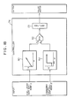
- Fig. 1 shows a drive control system for a hydraulic construction machine, according to a first embodiment of the invention.
- the drive control system comprises a prime mover or an engine 1, a hydraulic pump 2 driven by the engine 1, and a hydraulic actuator actuator 3 driven by discharge hydraulic fluid from the hydraulic pump 2.
- a control valve 4 is connected between the hydraulic pump 2 and the hydraulic actuator 3, for controlling flow rate and direction of the hydraulic fluid supplied from the hydraulic pump 2 to the hydraulic actuator 3.
- the prime mover 1 is preferably a diesel engine which comprises a fuel injection system provided with an all-speed governor.
- a first rotational speed setting device 7 is provided, which is composed of a first operating device or a fuel lever 5, and a governor lever 6 operatively connected to the fuel lever 5.
- the governor lever is operated in a direction B in response to the operation of the fuel lever 5, so that the rotational speed is set to a value in compliance with displacement of the fuel lever 5.
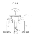
- the operation of the hydraulic actuator 3 is controlled by a second operating device 8.
- the second operating device 8 comprises an operating lever 9 and two hydraulic pilot valves 10 and 11.
- the hydraulic pilot valves 10 and 11 have their respective primary ports which are connected to a pilot pump 12 driven by the engine 1 and to a reservoir 13. Second ports of the respective hydraulic pilot valves 10 and 11 are connected respectively to pilot ports of the control valve 4 through respective pilot lines 14 and 15.
- the arrangement is such that the pilot valves 10 and 11 are supplied with primary pressure from the pilot pump 12, and secondary pressures in accordance with displacements of the respective pilot valves 10 and 11 are supplied respectively to the pilot ports of the control valve 4.
- the control valve 4 is controlled in position, that is, in stroke amount and direction, thereby controlling the flow rate and the direction of the hydraulic fluid supplied to the hydraulic actuator 3 to control the operation of the same.
- the second operating device 8 is also provided with springs 16 and 17 which serve to increase lever operating force when displacement of the operating lever 9, that is, an operating amount thereof exceeds a predetermined value X 0 .
- springs 16 and 17 serve to increase lever operating force when displacement of the operating lever 9, that is, an operating amount thereof exceeds a predetermined value X 0 .
- a second rotational speed setting device 20 which outputs a rotational speed control signal increasing the set rotational speed of the engine 1 as the displacement exceeds the predetermined value X 0 .
- a rotational speed control device 21 is associated with the second rotational speed setting device 20.
- the second rotational speed setting device 20 is composed of a pressure sensor 23 connected to the pilot lines 14 and 15 through a shuttle valve 22, for detecting the maximum pressure, and a controller 24 formed by a microcomputer or the like.
- a detecting signal from the sensor 23 is inputted into the controller 24, and the controller 24 executes a predetermined operation processing to obtain the above-mentioned rotational control signal and outputs the same.
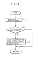
- the controller has inputted beforehand therein a control program as shown by a flow chart in Fig. 4, inclusive of the above predetermined value X 0 .
- the rotational speed control device 21 is comprised, for example, of a linear solenoid cylinder 25 which is adapted to extend a piston 26 in accordance with a level of the rotational control signal from the controller 24, to operate the governor lever 6 in the direction B.
- the detecting signal from the pressure sensor 23 is read into the controller 24 at a step S 1 .
- a step S 2 it is judged by the controller 24 whether or not displacement of the operating lever 9 indicated by the detecting signal exceeds the above-mentioned predetermined value X 0 which is set beforehand. If it is not judged that the displacement exceeds the predetermined value X 0 , the program skips a step S 3 and is returned to the start (step S 1 ). Accordingly, the rotational speed control signal is not outputted from the controller 24, and the linear solenoid cylinder 25 shown in Fig. 3 is not actuated. Thus, the governor lever 6 is operated only by the fuel lever 5, so that the rotational speed set by the fuel lever 5 is validated.
- the program proceeds to the step S 3 where the rotational speed control signal of a level corresponding to the read-in detecting signal is outputted.
- This rotational speed control signal is sent to the linear solenoid cylinder 25, to proportionally control the stroke amount of the piston 26.
- the governor lever 6 is operated by the linear solenoid cylinder 25, so that the rotational speed set by the controller 24 is validated.
- the rotational speed control device 21 is so arranged as to validate the rotational speed set by the first rotational speed setting device 7 in a first region Z 1 in which the displacement of the second operating device 8 is at least equal to or less than the above predetermined value X 0 , that is, is equal to or less than the predetermined value X 0 or the displacement X 1 larger than the predetermined value.
- the rotational speed control device 21 sets a rotational speed higher than the rotational speed set by the first rotational speed setting device 7, modified by the rotational speed control signal from the second rotational speed setting device 20 in a second region Z 2 in which the displacement is larger than the value X 0 or x
- the rotational speed control device 21 is so arranged as to validate the set rotational speed indicated by the rotational speed co.ntrol signal from the second rotational speed setting device 21 in the second region Z 2 .
- Fig. 7 is a graphical representation of one operational cycle which is a typical example of the operation conducted by the hydraulic excavator, in which 1 excavating, boom raising-swing, dumping and boom lowering-swing are repeated in the mentioned order.
- Fig. 7 shows the one operational cycle in relation to the engine output power required for each operation.
- N A is a set rotational speed of the engine suitable for giving the output power required for the light load operation
- N B is a set rotational speed suitable for giving the output power required for the usual heavy load operation
- N C is a set rotational speed suitable for giving the output power required for especially heavy load operation.
- Fig. 8 shows an output horsepower characteristic, a torque characteristic and a specific fuel consumption when the engine rotational speed is set to a selected one of the above values N A , N B and N C .
- the specific fuel consumption is brought to a value g lc and is excellent, at the relief excavation of the operation 1 and at acceleration at the initial stage of the swing in the operation 2, as shown in the operation 2, as shown in Fig. 8.
- the specific fuel consumption is brought to a value g 2c
- the specific fuel consumption is brought to a value g 3c'
- the specific fuel consumption is deteriorated.
- the specific fuel consumption is raised, for example, to g 2b and g 3 g.
- the engine rotational speed frequently fluctuates in interlocked relation to operation of the operating lever, during almost all of the period of time of the operations other than the boom lowering-swing operation, so that energy is consumed to accelerate the flywheel of the engine. This is not preferable in the specific fuel consumption.
- the rotational speed is set to a value of a desirable level in dependence upon displacement of the fuel level 5 in the first region Z l .
- the engine rotational speed is set to the value N B by the fuel lever 5, whereby the specific fuel consumption in the vicinity of g 2b is obtained at the usual excavating of 1 and at the usual swing of 2, and the specific fuel consumption in the vicinity of g3b more excellent than g 3c is obtained at the dumping of and at the boom lowering-swing of 4.
- the rotational speed of the engine is set by operation of the operating lever 9 at the relief excavating of 1 and at acceleration at the initial stage of the swing of 2, to obtain a higher set rotational speed, whereby the specific fuel consumption of g lc is obtained. In this manner, it is possible to obtain excellent specific fuel consumption as a whole.
- the above-mentioned predetermined value X is determined in consideration of the following points.
- the first point is as follows.
- the engine rotational speed is set by the fuel lever 5 to a value in the vicinity of the idling N. which is employed in the lightest load operation such as normal plane operation or the like
- the discharge quantity of the hydraulic pump 2 is detemrined by the rotational speed.
- the control valve 4 begins to be opened in dependence upon displacement of the operating lever, and the requisite flow rate required by the control valve and the flow rate of fluid passing through the control valve flowing at the discharge quantity of the hydraulic pump are brought into coincidence with each other at a certain specific opening degree of the control valve.
- the first point is to bring the displacement of the operating lever 9-indicating the specific opening degree to X O .
- the displacement of the operating lever 9 is brought to a value obtaining the opening degree of the control valve 4 at which the flow rate of fluid passing through the control valve 4 obtained by restricting the discharge quantity of the hydraulic pump 2 is brought into coincidence with the requisite flow rate.
- the engine rotational speed can be set in interlocked relation to the operating lever in a region equal to or higher than the predetermined value X or X 1 .
- the second point is the displacement of the operating lever 9 which obtains a valve opening degree corresponding to an upper limit of a metering region of the control valve 4 required for the fine or minute operation working.
- the displacement of the operating lever 9 and the set rotational speed of the engine are brought to the linear proportional relationship in the second region Z 2 as shown in Figs. 5 and 6, but are not limited only to this relationship.
- the arrangement may be such that the opening degree of the control valve 4 is calculated on the basis of displacement of the operating lever 9, and an engine rotational speed control signal is outputted which can obtain discharge quantity of the hydraulic pump 2 corresponding to the requisite flow rate prescribed by the opening degree.
- the engine rotational speed increases in predetermined functional relation other than the linear proportion to the displacement of the operating lever.
- a rotational speed control device 32 may be composed of an electromagnetic directional control valve 30 turned on and off in response to the rotational speed control signal, and a hydraulic cylinder 31 movable between ON and OFF positions in accordance with the position of the directional control valve 30.
- the relationship between displacement of the operating lever 9 and the set rotational speed of the engine is brought to one as shown in Fig. 10 of the rotational speed set by the fuel lever 5 is the idling N., and to one as shown in Fig. 11 if the rotational speed set by the fuel lever 5 is the intermediate rotational speed N 1 .
- the predetermined value forming the boundary between the first and second regions Z 1 and Z 2 is X 0 and is constant independently of the rotational speed set by the fuel lever 5, while the set rotational speed is brought to the maximum value N max in the second region Z 2 independently of displacement of the operating lever 9.
- each of the above-described embodiments is such that the rotational speed control device 21, 32 validates the rotational speed set by the rotational speed control signal obtained by the second rotational speed setting device 20 in the second region Z 2 .
- an arrangement different from the above arrangement also in this respect can be employed.
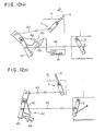
- Figs. 12(a) through 12(c) shows an embodiment having such arrangement, in which the reference numeral 40 denotes a rotational speed control device.
- the rotational speed control device 40 is so arranged as to add the rotational speed set by the rotational speed control signal to the set rotational speed obtained by the fuel lever 5 in the above-mentioned second region Z 2*
- the fuel lever 5 is pivotally supported by a console box 41 within an operator's cab, and is connected, through a push-pull cable 43, to one end of a first intermediate lever 42 which is pivotally supported at a predetermined portion of the vehicle.
- the first intermediate lever 42 has the other end to which a linear solenoid cylinder 44 is fixedly mounted.
- a second intermediate lever 45 is pivotally supported in coaxial relation to the first intermediate lever 42. Pivotal movement of the first intermediate lever 42 is transmitted to the second intermediate lever 45 through the linear solenoid cylinder 44.
- the second intermediate lever 45 is connected to the governor lever 6 through a push-pull cable 46.
- the rotational speed control signal is supplied from the controller 24 of the second control setting means 20 to the linear solenoid cylinder 44, so that a stroke amount corresponding to the magnitude of the signal is obtained at the linear solenoid cylinder 44.
- An idling position is a position where pivotal movement of the fuel lever 5 in the direction A causes the forward end of the linear solenoid cylinder 25 to be brought into engagement with the second intermediate lever 45.
- the set rotational speed of the engine 1 is a constant value N i in the first region Z 1 of from zero to the predetermined value X 0 of displacement of the operating lever 9.
- a rotational speed control value increasing in proportion to the displacement is obtained at the second rotational speed setting device 20.
- a rotational speed control signal corresponding to the rotational speed control valve is sent to the linear solenoid cylinder 44, so that the linear solenoid cylinder 44 extends with a stroke in dependence upon the rotational speed control signal.
- the set rotational speed increases in the second region Z 2 as indicated by the line l 1 in Fig. 13.
- the linear solenoid cylinder 44 may be formed by an actuator operable between ON and OFF positions. In this case, the relationship of the set rotational speed of the engine with respect to displacement of the operating lever 9 is brought to one shown in Fig. 14.
- Fig. 15 shows an embodiment having such arrangement.
- component parts similar to those illustrated in Fig. 1 are designated by the same reference numerals.
- a second rotational speed setting device 60 comprises a directional control valve 61 which is controlled in switching as the secondary pressure of the operating device 8 formed by a pilot valve exceeds a predetermined value corresponding to the predetermined value X 0 of displacement of the operating lever 9, and a rotational speed control device 62 comprises a proportional control hydraulic cylinder 63 which is extended and retracted directly by the secondary pressure of the operating device 8 transmitted through the directional control valve 61. That is, when the secondary pressure of the operating device 8 is equal to or lower than the predetermined value, the directional control valve 61 is in the illustrated position where transmission of the secondary pressure is blocked.
- the directional control valve 61 is switched to the other position where the secondary pressure is applied to the hydraulic cylinder 63 as a rotational speed control signal, so that the hydraulic cylinder 63 is extended with a stroke amount corresponding to the pressure.
- the relationship between displacement of the operating lever 9 and the set rotational speed of the engine 1 is brought to one shown in Figs. 5 and 6 in dependence upon the rotational speed set by the fuel lever 5.
- the hydraulic cylinder 63 is controlled in an ON and OFF manner, the relationship between the aforesaid displacement and the set rotational speed is brought to one shown in Figs. 10 and 11.
- the arrangement illustrated in Figs. 12(a) through 12(c) is employed so as to add the value set by tne second rotational speed setting device 60, the relationship between displacement of the operating lever and the set rotational speed is brought to one shown in Fig. 13.
- control is carried out in an ON and OFF manner, the relationship is brought to one shown in Fig. 14.
- Fig. 16 shows an embodiment having such arrangement, in which component parts similar to those illustrated in Fig. 1 are designated by the same reference numerals.
- the embodiment includes two hydraulic actuators 3 and 70 and, correspondingly, two operating devices 8 and 71 for respectively controlling operations of the respective hydraulic actuators.
- the operating device 71 has an operating lever 72.
- displacement of the fuel lever 5 is electrically detected by a displacement detector 73, and a signal indicative of the detection is inputted into a controller 74.
- displacements of the respective operating levers 9 and 72 are also electrically detected respectively by detecting devices 75 and 76, and signals indicative of the respective detections are sent to the controller 74.
- the controller 74 coordinates these signals, and outputs a command signal instructing a final set rotational speed, to a pulse motor 77 which forms a rotational speed control device.
- the pulse motor 77 rotates by an angular extent corresponding to the command signal, to drive the governor lever 6 through a linkage 78.
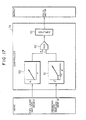
- the controller 74 is arranged as illustrated in Fig. 17. That is, the controller 74 comprises arithmetic means 80 or first rotational speed setting means for setting the rotational speed N to a value in accordance with displacement of the fuel lever 5, arithmetic means 81 or second rotational speed control means for outputting, as a rotational speed control signal, a rotational speed N' increasing in response to displacements of the respective operating levers 9 and 72 when their respective displacements exceed the predetermined value X I O , a maximum value selector 82 for selecting the maximum value of the outputs of the respective first and second arithmetic means 80 and 81, and an amplifier 83 for amplifying an output from the maximum value selector 82, wherein the pulse motor 77 is driven by an output from the amplifier 83.
- the predetermined value X' 0 corresponds to the predetermined value X shown
- the controller 74 is arranged as shown in Fig. 18. That is, the controller 74 comprises second arithmetic means 84 for setting a constant maximum rotational speed N' when displacements of the respective operating levers 9 and 72 exceed the predetermined value X' 0 , in substitution for the second arithmetic means 81 shown in Fig. 17.
- the controller 74 is arranged as illustrated in Fig. 19.
- second arithmetic means 85 is provided which outputs a rotational speed a increasing in accordance with displacements of the respective operating levers 9 and 72 as their respective displacements exceed the predetermined value X' 0 .
- an adder 86 is provided which adds the outputs from the respective first and second arithmetic means 80 and 85 to each other.
- the controller 74 is provided, as shown in Fig. 20, with second arithmetic means 87 which outputs a constant maximum rotational speed a as the displacements of the respective operating levers 9 and 72 exceed the predetermined value X' 0 , in place of the second arithmetic means 85 illustrated in Fig. 19.
- the relationship between displacement of the operating lever 9 and the stroke amount determining the opening degree of the control valve 4 is set such that, the stroke amount of the control valve is so set as not to reach the maximum value when the displacement of the operating lever reaches the predetermined value X 0 , but as to be brought to an intermediate stroke amount.
- setting can be made such that the stroke amount of the control valve 4 is brought to the maximum value (maximum in opening degree), when the operating lever 9 is operated up to the predetermined value X 0 .
- the arrangement of this embodiment is such that a hydraulic pump 90 of variable capacity type is employed, and a displacement volume of the hydraulic pump is varied by a displacement volume control device 91 which regulates an angle of inclination of a swash plate of the hydraulic pump.
- a controller 92 forms a second rotational speed setting device 93 for outputting a rotational speed control signal to the rotational speed control device 21.
- the controller 92 also outputs a displacement volume control signal to the displacement volume control device 91.
- the controller 92 has stored therein a control program as indicated by a flow chart in Fig. 24.
- a detecting signal from the pressure sensor 23 is read into the controller 92. It is judged at a step S 2 whether or not displacement of the operating lever 9 indicated by the detecting signal exceeds the predetermined value X 0 . If it is judged that the displacement exceeds the predetermined value, the rotational speed control signal increasing the set rotational speed of the engine 1 in proportion to the displacement is outputted at a step S 3 . At the same time, the displacement volume control signal reducing the displacement volume (angle of inclination) in dependence upon the increase in the set rotational speed is outputted to the displacement volume control device 91.
- the displacement volume control signal is so determined as to reduce the displacement volume such that the discharge quantity of the hydraulic pump is brought substantially to a constant value with respect to the increase in the engine rotational speed.
- the arrangement of the present embodiment is such that the stroke amount of the control valve 4 is brought to the maximum value, that is, the valve opening degree is brought to the maximum value, at the predetermined value x 0 of the operating lever displacement.
- the discharge quantity of the hydraulic pump 90 increases in proportion to an increase in the engine rotational speed until the engine rotational speed reaches a value N 0 corresponding to the predetermined value X 0 of the operating lever displacement, because the displacement volume is constant.
- the discharge quantity is brought to a constant value Q O until the discharge quantity reaches the maximum value N max as described above.
- the relationship between the pump discharge pressure P and the pump discharge quantity Q at this time is brought to one shown in Fig. 27.
- the relationship indicates a P - Q characteristic as shown by the dot-and-chain line in the running condition of the rotational speed N 0 , and indicates a P - Q characteristic as shown by the solid line in the running condition of the rotational speed N max .
- the P - Q characteristic varies continuously between the dot-and-chain line and the solid line in response to variation in the rotational speed.
- the region in which the pump discharge quantity Q is constant at Q O increases from P 0 to P 1 of the pump pressure, and the absorption horsepower also increase correspondingly.
- the pump discharge quantity Q 0 is controlled to a constant value in the range equal to or higher than the engine rotational speed N 0 , it is made possible to increase the consumptive horsepower correspondingly to an increase in the engine rotational speed.
- the engine horsepower can effectively be utilized while the operating speed is maintained constant.
- the control valve 4 is maintained at the maximum opening degree like the present embodiment, the entire pump discharge quantity can be supplied to the hydraulic actuator 3, whereby it is made possible to more effectively utilize the engine horsepower.
- the displacement volume control device 91 may be composed, for example, of a hydraulic cylinder and a linear solenoid valve proportionally controlled by the signal from the controller 92.
- Fig. 23 can also be arranged electronically, like the embodiment shown in Fig. 16.
- Fig. 28 shows an embodiment having such arrangement, in which component parts similar to those shown in Figs. 16 and 23 are designated by the same reference numerals. That is, a controller 95 has inputted thereinto a signal from the displacement detector 73 for detecting displacement of the fuel lever 5, and signals from the respective detecting devices 75 and 76 for detecting displacements of the respective operating levers 9 and 7 2 .
- the controller 75 outputs a commmand signal instructing a final set rotational speed to the pulse motor 77, and outputs a displacement volume control signal to a displacement volume control device 96 formed by a linear solenoid cylinder.
- the controller 95 is arranged as shown in Fig. 29.
- component parts similar to those illustrated in Fig. 17 are designated by the same reference numerals. That is, in addition to the arithmetic means 80 and 82'for generating command signals to the pulse motor 77, the maximun value selector 82 and the amplifier 83, the controller 95 comprises arithmetic means 97 into which displacement signals x' from the respective operating levers 9 and 72 are inputted.
- the arithmetic means 97 outputs, as a displacement volume control signal, such a displacement volume q as to maintain the displacement volume (angle of inclination) to the maximum value until the displacement signals reach the predetermined value x' n , and to decrease the displacement volume in dependence upon an increase in the displacements as the displacement signals exceed the predetermined value x' 0 .
- the output from the arithmetic means 97 is given to the linear solenoid cylinder 96.
- Fig. 30 shows an embodiment having such arrangement, in which component parts similar to those illustrated in Fig. 17 are designated by the same reference numerals.
- the entire system arrangement of this embodiment is intended for the system as shown in Fig. 16.
- the number of the hydraulic actuators 3 and 70 or the number of the operating devices .8 and 71 may optionally be increased to two or more.
- a controller 100 in place of the arithmetic amplifier 81 shown in Fig. 17, a controller 100 comprises an adder 101 for adding respective displacements x 1 , x 2 , x 3' ... of the plurality of operating levers 9, 72, ... to each other, and arithmetic means 102 for outputting, as a rotational speed control signal, a rotational speed N ' increasing in dependence upon the displacements as the added total value x' exceeds a predetermined value x' 0 .
- a controller 100 comprises an adder 101 for adding respective displacements x 1 , x 2 , x 3' ... of the plurality of operating levers 9, 72, ... to each other, and arithmetic means 102 for outputting, as a rotational speed control signal, a rotational speed N ' increasing in dependence upon the displacements as the added total value x' exceeds a predetermined value x' 0 .
- the maximum horsepower can optionally be set in compliance with the operational contents in the first region in which the rotational speed set by the first rotational speed setting means is validated. Accordingly, it is possible to improve the specific fuel consumption. In the second region in which rotational speed higher than the set rotational speed is set, it is possible to obtain the maximum horsepower suitable for the heavy load operation, so that the heavy load operation can be carried out under the optimum specific fuel consumption.
- the rotational speed does not fluctuate even if the second operating means is operated, fluctuation of the rotational speed of the prime mover due to the second operating means can be reduced as a whole, so that it is possible to diminish problems such as deterioration of the specific fuel consumption, smoke emission and noises due to the fluctuation.
- it is possible to optionally set the rotational speed of the level suitable for the operational contents in the first region excellent operability can be secured.
Abstract
Description
- The present invention relates to a drive control system for hydraulic construction machines represented by a hydraulic excavator, a wheel loader and the like and, particularly, to a drive control system for a hydraulic construction machine, which comprises a prime mover and a hydraulic pump driven thereby.
- In general, a conventional drive control system for a hydraulic construction machine comprises a prime mover, a hydraulic pump driven by the prime mover, a hydraulic actuator driven by discharge hydraulic fluid from the hydraulic pump, rotational speed setting means including a fuel lever for setting rotational speed of the prime mover, and an operating lever for controlling operation of the hydraulic actuator. Connected between the hydraulic pump and the hydraulic actuator is a control valve for controlling flow rate and direction of the discharge hydraulic fluid from the hydraulic pump. Operation of the operating lever controls the position of the control valve to control operation of the hydraulic actuator.
- In the above conventional system, rotational speed of the prime mover or an engine is set by displacement of the fuel lever, to vary a horsepower characteristic of the engine in accordance with the set rotational speed. The maximum horsepower of the engine is determined on the basis of the horsepower characteristic. Specific fuel consumption (g/PS.h) of the engine is determined depending upon the set rotational speed and the magnitude of an operational load at that time. If, for example, the rotational speed is set to the maximum value, the specific fuel consumption is brought to the best value, at the heavy load operation in the vicinity of the maximum horsepower of the horsepower characteristic obtained by the set rotational speed. On the other hand, at the light load operation which requires only horsepower lower than the maximum horsepower, the engine rotational speed increases to a value higher than the rotational speed at the maximum horsepower of the horsepower characteristic, so that the specific fuel consumption is deteriorated. In general, at the actual operation of the hydraulic excavator, for example, the proportion of the operation which is carried out under the load excellent in the specific fuel consumption is extremely low. For example, in one operational cycle including ① excavating, ② boom raising-swing, G) dumping and boom lowering swing which are repeated in the mentioned order, the operations necessitating the above-mentioned maximum horsepower are only the relief excavating during the operation ① and the operation at acceleration at the initial stage of the swing during the
operation ②. Thus, it is not preferable from the energy-saving point of view to set the rotational speed to the maximum value. - In the drive control system of the kind referred to above, Japanese Patent Application Laid-Open No. 52-53189 has proposed an arrangement in which not only is the rotational speed of the engine set by the fuel lever, but also the engine rotational speed is interlocked with the operating lever for controlling operation of the hydraulic actuator in such a manner that when the operating lever is operated, the engine rotational speed is set also by displacement of the operating lever, to vary the horsepower characteristic, thereby controlling the maximum horsepower. With this arrangement, when displacement of the operating lever is small, the engine rotational speed is set to a low value to give the maximum horsepower required for the light load operation, while as the displacement increases, the engine rotational speed is set to a high value to raise also the maximum horsepower of the engine so as to give the maximum horsepower required for the heavy load operation. Thus, the operation is carried out always in a region excellent in the specific fuel consumption, thereby preventing deterioration of the specific fuel consumption. Further, in a similar drive control system, Japanese Patent Application Laid-Open No. 58-204940 has proposed an arrangement in which only a specific operating lever is interlocked with the engine rotational speed, and only when the operating lever is operated, the engine rotational speed is set by displacement of the operating lever to vary the horsepower characteristic, thereby controlling the maximum horsepower. In this system, low rotational speed providing the maximum horsepower required for the light load operation is set by the fuel lever and, usually, the operation is carried out with the horsepower characteristic obtained at the low set rotational speed. When the specific operating lever is operated, the rotational speed is set, in interlocked relation to the operation of the operating lever, to a value higher than that set by the fuel lever, so as to give the maximum horsepower required for the heavy load operation with the horsepower characteristic obtained at the set rotational speed, like the above-described conventional system. Thus, the operation is carried out always in a region excellent in the specific fuel consumption, thereby preventing deterioration of the specific fuel consumption.
- Furthermore, in the drive control system described above, Japanese Patent Application No. 59-129957 has proposed an arrangement comprising, in place of the control valve, a hydraulic pump of variable capacity type and means for varying an angular position of a swash plate of the hydraulic pump, that is, a displacement volume of the hydraulic pump by the operating lever, wherein the engine rotational speed is controlled only by the operating lever, the engine rotational speed is set to a low value when displacement of the operating lever is equal to or lower than a predetermined value, and as the displacement of the operating lever exceeds the predetermined value, the rotational speed is set to a high value in dependence upon the displacement of the operating lever, also in this system, like the above-mentioned conventional system, an attempt can be made to improve the specific fuel consumption, because, in the displacement of the operating lever equal to or larger than the predetermined value, the engine rotational speed is set on the basis of the displacement of the operating lever.
- In addition to the above-mentioned patents, Japanese Patent Application Laid-Open Nos. 48-53162 and 50-15980, and Japanese Patent Publication No. 60-38561 are listed as being relevant to the arrangement in which the engine rotational speed is interlocked with operation of the operating lever. Moreover, U.S. Patent Serial No. 947,524 (corresponding to EPC Application No. 86118113.9) is listed, which discloses an arrangement in which the engine rotational speed is controlled in response to operation modes or the actuator load.
- In the system disclosed in Japanese Patent Application Laid-Open Nos. 52-53189 and 58-204940, however, operation of the operating lever setting the engine rotational speed by the operating lever is effected substantially over the entire range of the operating lever. Accordingly, each time displacement of the operating lever varies by operation thereof, the set rotational speed varies, so that the engine rotational speed frequently fluctuates during almost all of a period of time within which the operating lever is operated. In, for example, the above-mentioned operational cycle, when the fuel lever is operated to set the rotational speed to a low value suitable for the
operation ④ which is minimum in the requisite horsepower, operation of the operating lever causes the engine rotational speed to frequently fluctuate at the operations other than theoperation ④. This requires power for accelerating a flywheel of the engine, resulting in consumption of the fuel. Thus, there has been a problem that the specific fuel consumption is not necessarily improved. Further, there have also been problems that smoke emission and noises occur due to fluctuation of the engine rotational speed. - Moreover, the system disclosed in the latter Japanese Patent Application Laid-Open No. 58-204940 has also the following problem. That is, when an operating lever other than the specific operating lever is operated, the rotational speed set by the fuel lever is low and, therefore, it is impossible to carry out the operation necessitating the output power equal to or higher than the maximum horsepower obtained with the horsepower characteristic at the set rotational speed. Thus, a bad influence is exerted upon the operability. Specifically, for example, in the above-mentioned operational cycle, when an operating lever carrying out the boom raising-swing operation O2 is selected as the specific operating lever, the requisite maximum horsepower cannot be obtained at the relief excavating of the operation CD. In other words, it is impossible for the operating lever other than the specific operating lever to effectively utilize the maximum horsepower which the engine has.
- Furthermore, in the system disclosed in Japanese Patent Application No. 59-129957, the arrangement is such that the engine rotational speed is set to a constant low value in a region of operation of the operating lever equal to or less than the predetermined displacement. Since, however, the constant value is fixedly determined, the operating lever must be operated with displacement equal to or larger than the predetermined value to set the engine rotational speed to a higher value, at the operation necessitating the maximum horsepower higher than that obtained with the horsepower characteristic of the set low rotational speed. Also in this case, the engine rotational speed frequently fluctuates, giving rise to problems such as deterioration of the specific fuel consumption, smoke emission and generation of noises. For example, in the above-mentioned operational cycle, when the constant rotational speed is set to a low value suitable for the
operation ④ lowest in the requisite horsepower, operation of the operating lever causes the engine rotational speed to frequently fluctuate at the operations other than theoperation ④. This raises problems such as deterioration of the specific fuel consumption due to acceleration of the flywheel, smoke emission and noises. In addition, when the constant rotational speed is set to a high value, the engine rotational speed is brought to a high value inferior in the specific fuel consumption from the horsepower characteristic point of view, at the operation which necessitates only the horsepower lower than the maximum horsepower obtained with the horsepower characteristic of the constant rotational speed, thereby making it impossible to achieve the original object. That is, in the above-mentioned operational cycle, when the constant rotational speed is set to an intermediate value suitable for the usual excavating operation of CD and the swing operation subsequent to the initial acceleration of ②, the specific fuel consumption is deteriorated at theoperations - Furthermore, since the constant rotational speed is determined in a fixed fashion, even if an operator desires operation in which noises and smoke emission due to fluctuation of the rotational speed are not caused, it is impossible to carry out such desired operation. Thus, there has been a problem regarding the operability.
- It is therefore an object of the invention to provide a drive control system for a hydraulic construction machine, which can improve the specific fuel consumption and can reduce fluctuation in rotational speed of an engine, and which is superior in operability.
- The above object is achieved by a drive control system for a construction machine, comprising a prime mover, a hydraulic pump driven by the prime mover, at least one hydraulic actuator driven by discharge hydraulic fluid from the hydraulic pump, first rotational speed setting means including first operating means for setting rotational speed of the prime mover, and second operating means for controlling operation of the hydraulic actuator, characterized by comprising second rotational speed setting means associated with the second operating means for outputting a rotational speed control signal increasing the set rotational speed when displacement of the second operating means exceeds a predetermined value, and rotational speed control means associated with at least the second rotational speed setting means, for validating the rotational speed set by the first rotational speed setting means in a first region in which displacement of the second operating means is at least equal to or less than the predetermined value, and for setting a rotational speed higher than the rotational speed set by the first rotational speed setting means, modified by the rotational speed control signal from the second rotational speed setting means in a second region in which the displacement of the second operating means is larger than the predetermined value.
- With the arrangement as above, in the first region in which the rotational speed set by the first rotational speed setting means is validated, the rotational speed of a desirable level in compliance with the displacement of the first operating means is set. Accordingly, since it is possible to optionally set the maximum horsepower in the first region in accordance with the operational contents, the specific fuel consumption can be improved. Further, since, in the second region, the rotational speed is set by the second operating means to the value higher than the rotational speed set by the first rotational speed setting means, the maximum horsepower suitable for the heavy load operation can be obtained, making it possible to carry out the heavy load operation under the optimum specific fuel consumption. Moreover, since, in the first region, setting of the rotational speed by the second operating means is not carried out, the rotational speed does not fluctuate even if the second operating means is operated, so that no problems arise regarding smoke emission and noises due to the fluctuation of the rotational speed. Accordingly, it is possible to reduce fluctuation of the rotational speed of the prime mover due to the second operating means as a whole in the operation, so that problems are diminished such as deterioration of the specific fuel consumption, smoke emission and noises due to the fluctuation of the rotational speed. Moreover, since the first rotational speed setting means can optionally set the rotational speed of a level suitable for the operational contents in the first-region, it is possible to secure excellent operability.
-
- Fig. 1 is a diagrammatic view showing the entirety of a drive control system for a hydraulic construction machine according to a first embodiment of the invention;
- Fig. 2 is a detailed view of an operating device in the drive control system;
- Fig. 3 is a detailed view of a rotational speed control device in the drive control system;
- Fig. 4 is a flow chart for explanation of operation of a controller in the drive control system;
- Figs. 5 and 6 are characteristic graphs showing the relationship between displacement of an operating lever and set rotational speed of an engine in the drive control system;
- Fig. 7 is a graphical representation of a requisite engine output power in one operational cyclic, for explanation of the operation of the drive control system;
- Fig. 8 is a graphical representation of characteristics of respective output horsepower, torque and specific fuel consumption when the rotational speed of the engine is varied;
- Fig. 9 is a diagrammatic view showing a modification of the rotational speed control device;
- Figs. 10 and 11 are characteristic graphs showing the: relationship between displacement of the operating lever and the set rotational speed of the engine when the rotational speed control device illustrated in Fig. 9 is employed;
- Figs. 12(a), 12(b) and 12(c) are diagrammatic views respectively showing operating positions different from each other, in another modification of the rotational speed control device;
- Fig. 13 is a characteristic graph showing the relationship between displacement of the operating lever and the set rotational speed of the engine when the rotational speed control device illustrated in Figs. 12(a) through 12(c) is employed;
- Fig. 14 is a characteristic view when the rotational speed control device is further modified;
- Fig. 15 is a diagrammatic view showing the entirety of a drive control system according to another embodiment of the invention;
- Fig. 16 is a diagrammatic view showing the entirety of a drive control system when the embodiment illustrated in Fig. 1 is arranged electronically;
- Fig. 17 is a view showing the contents of a controller of the drive control system illustrated in Fig. 16.
- Fig. 18 is a view showing the contents of the controller when the characteristics illustrated in Figs. 10 and 11 are given to the drive control system shown in Fig. 16;
- Fig. 19 is a view showing the contents of the controller when the characteristic illustrated in Fig. 13 is given to the drive control system shown in Fig. 16;
- Fig. 20 is a view showing the contents of the controller when the characteristic illustrated in Fig. 14 is given to the drive control system shown in Fig. 16;
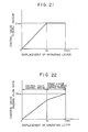
- Fig. 21 is a graphical representation of the relationship between displacement of the operating lever and a stroke amount of a control valve in an embodiment in which the displacement and the stroke amount are set especially;
- Fig. 22 is a graphical representation of the relationship between displacement of the operating lever and flow rate of fluid passing through the control valve in the embodiment illustrated in Fig. 21;
- Fig. 23 a diagrammatic view showing the entirety of a drive control system according to still another embodiment of the invention;
- Fig. 24 is a flow chart for explanation of operation of a controller in the drive control system illustrated in Fig. 23;
- Fig. 25 is a graphical representation of the relationship between displacement of an operating lever and flow rate of fluid passing through a control valve in the drive control system illustrated in Fig. 23;
- Fig. 26 is a graphical representation of the relationship between engine rotational speed and a pump discharge quantity in the drive control system illustrated in Fig. 23;
- Fig. 27 is a graphical representation of the relationship between pump discharge pressure and the pump discharge quantity in the drive control system illustrated in Fig. 23;
- Fig. 28 is a diagrammatic view showing the entirety of a drive control system when the embodiment illustrated in Fig. 23 is arranged electronically;
- Fig. 29 is a view showing the contents of a controller in the drive control system illustrated in Fig. 28; and
- Fig. 30 is a view showing the contents of a controller in a drive control system according to still another embodiment of the invention.
- Preferred embodiments of the invention will be described below with reference to the drawings.
- Fig. 1 shows a drive control system for a hydraulic construction machine, according to a first embodiment of the invention. The drive control system comprises a prime mover or an engine 1, a
hydraulic pump 2 driven by the engine 1, and ahydraulic actuator actuator 3 driven by discharge hydraulic fluid from thehydraulic pump 2. Acontrol valve 4 is connected between thehydraulic pump 2 and thehydraulic actuator 3, for controlling flow rate and direction of the hydraulic fluid supplied from thehydraulic pump 2 to thehydraulic actuator 3. - The prime mover 1 is preferably a diesel engine which comprises a fuel injection system provided with an all-speed governor. In order to set rotational speed of this engine, a first rotational
speed setting device 7 is provided, which is composed of a first operating device or afuel lever 5, and agovernor lever 6 operatively connected to thefuel lever 5. In this first rotationalspeed setting device 7, as thefuel lever 5 is operated in a direction A, the governor lever is operated in a direction B in response to the operation of thefuel lever 5, so that the rotational speed is set to a value in compliance with displacement of thefuel lever 5. - The operation of the
hydraulic actuator 3 is controlled by asecond operating device 8. As shown in Fig. 2, thesecond operating device 8 comprises an operating lever 9 and twohydraulic pilot valves 10 and 11. Thehydraulic pilot valves 10 and 11 have their respective primary ports which are connected to apilot pump 12 driven by the engine 1 and to areservoir 13. Second ports of the respectivehydraulic pilot valves 10 and 11 are connected respectively to pilot ports of thecontrol valve 4 throughrespective pilot lines pilot valves 10 and 11 are supplied with primary pressure from thepilot pump 12, and secondary pressures in accordance with displacements of therespective pilot valves 10 and 11 are supplied respectively to the pilot ports of thecontrol valve 4. In response to receipt of the secondary pressures, thecontrol valve 4 is controlled in position, that is, in stroke amount and direction, thereby controlling the flow rate and the direction of the hydraulic fluid supplied to thehydraulic actuator 3 to control the operation of the same. - The
second operating device 8 is also provided withsprings - Associated with the
second operating device 8 is a second rotationalspeed setting device 20 which outputs a rotational speed control signal increasing the set rotational speed of the engine 1 as the displacement exceeds the predetermined value X0. A rotationalspeed control device 21 is associated with the second rotationalspeed setting device 20. - The second rotational
speed setting device 20 is composed of apressure sensor 23 connected to thepilot lines shuttle valve 22, for detecting the maximum pressure, and acontroller 24 formed by a microcomputer or the like. A detecting signal from thesensor 23 is inputted into thecontroller 24, and thecontroller 24 executes a predetermined operation processing to obtain the above-mentioned rotational control signal and outputs the same. The controller has inputted beforehand therein a control program as shown by a flow chart in Fig. 4, inclusive of the above predetermined value X0. - As shown in Fig. 3, the rotational
speed control device 21 is comprised, for example, of alinear solenoid cylinder 25 which is adapted to extend apiston 26 in accordance with a level of the rotational control signal from thecontroller 24, to operate thegovernor lever 6 in the direction B. - The operation of the embodiment will next be described with reference to the flow chart shown in Fig. 4.
- When the program starts, the detecting signal from the
pressure sensor 23 is read into thecontroller 24 at a step S1. At a step S2, it is judged by thecontroller 24 whether or not displacement of the operating lever 9 indicated by the detecting signal exceeds the above-mentioned predetermined value X0 which is set beforehand. If it is not judged that the displacement exceeds the predetermined value X0, the program skips a step S3 and is returned to the start (step S1). Accordingly, the rotational speed control signal is not outputted from thecontroller 24, and thelinear solenoid cylinder 25 shown in Fig. 3 is not actuated. Thus, thegovernor lever 6 is operated only by thefuel lever 5, so that the rotational speed set by thefuel lever 5 is validated. On the other hand, if it is judged at the step s2 that the displacement of the operating lever 9 exceeds the predetermined value X0, the program proceeds to the step S3 where the rotational speed control signal of a level corresponding to the read-in detecting signal is outputted. This rotational speed control signal is sent to thelinear solenoid cylinder 25, to proportionally control the stroke amount of thepiston 26. Thus, thegovernor lever 6 is operated by thelinear solenoid cylinder 25, so that the rotational speed set by thecontroller 24 is validated. - With the arrangement described above, when the rotational speed of the engine 1 is set to an idling N. by the
fuel lever 5, as shown in Fig. 5, the set rotational speed at the idling Ni is maintained until the displacement of the operating lever 9 reaches the predetermined value X0. As the displacement exceeds X0, the set rotational speed of the engine increases in proportion to displacement of the operating lever 9, and reaches the maximum value Nmax at the maximum displacement Xmax. When the engine rotational speed is set to an intermediate value Nl by thefuel lever 5, as shown in Fig. 6, the set rotational speed being to increase as the displacement of the operating lever 9 exceeds a value X1 at which a set rotational speed N1 is obtained. - In this manner, the rotational
speed control device 21 is so arranged as to validate the rotational speed set by the first rotationalspeed setting device 7 in a first region Z1 in which the displacement of thesecond operating device 8 is at least equal to or less than the above predetermined value X0, that is, is equal to or less than the predetermined value X0 or the displacement X1 larger than the predetermined value. In addition, the rotationalspeed control device 21 sets a rotational speed higher than the rotational speed set by the first rotationalspeed setting device 7, modified by the rotational speed control signal from the second rotationalspeed setting device 20 in a second region Z2 in which the displacement is larger than the value X0 or x Particularly in this embodiment, the rotationalspeed control device 21 is so arranged as to validate the set rotational speed indicated by the rotational speed co.ntrol signal from the second rotationalspeed setting device 21 in the second region Z2. - Advantageous effects of the drive control system constructed as above will next be described.
- Fig. 7 is a graphical representation of one operational cycle which is a typical example of the operation conducted by the hydraulic excavator, in which ① excavating, boom raising-swing, dumping and boom lowering-swing are repeated in the mentioned order. Fig. 7 shows the one operational cycle in relation to the engine output power required for each operation. In the figure, NA is a set rotational speed of the engine suitable for giving the output power required for the light load operation, NB is a set rotational speed suitable for giving the output power required for the usual heavy load operation, and NC is a set rotational speed suitable for giving the output power required for especially heavy load operation. Further, Fig. 8 shows an output horsepower characteristic, a torque characteristic and a specific fuel consumption when the engine rotational speed is set to a selected one of the above values NA, N B and NC.
- In the one operational cycle shown in Fig. 7, when the engine rotational speed is set to a constant value of the highest one NC, the specific fuel consumption is brought to a value glc and is excellent, at the relief excavation of the operation ① and at acceleration at the initial stage of the swing in the
operation ②, as shown in theoperation ②, as shown in Fig. 8. At other operations, for example, at usual swing in theoperation ②, the specific fuel consumption is brought to a value g2c, and at boom lowering swing in theoperation ④, the specific fuel consumption is brought to a value g 3c' Thus, the specific fuel consumption is deteriorated. Accordingly, if the rotational speed is set by the fuel lever to the value N suitable for theoperation ④, and if the engine rotational speed is set to appropriate values in dependence upon the respective operations in interlocked relation to the operating lever, the specific fuel consumption is raised, for example, to g2b and g3g. In this case, however, the engine rotational speed frequently fluctuates in interlocked relation to operation of the operating lever, during almost all of the period of time of the operations other than the boom lowering-swing operation, so that energy is consumed to accelerate the flywheel of the engine. This is not preferable in the specific fuel consumption. There also exist problems of smoke emission and noises due to fluctuation of the engine rotational speed. - In the drive control system of the embodiment, the rotational speed is set to a value of a desirable level in dependence upon displacement of the
fuel level 5 in the first region Zl. By doing so, in the above-mentioned operational example, the engine rotational speed is set to the value NB by thefuel lever 5, whereby the specific fuel consumption in the vicinity of g2b is obtained at the usual excavating of ① and at the usual swing of ②, and the specific fuel consumption in the vicinity of g3b more excellent than g3c is obtained at the dumping of and at the boom lowering-swing of ④. On the other hand, since, in the second region Z2, the rotational speed is set to the higher value by the operating lever 9, the rotational speed of the engine is set by operation of the operating lever 9 at the relief excavating of ① and at acceleration at the initial stage of the swing of ②, to obtain a higher set rotational speed, whereby the specific fuel consumption of glc is obtained. In this manner, it is possible to obtain excellent specific fuel consumption as a whole. - Since, in the first region Z1, setting of the rotational speed by means of the operating lever 9 is not carried out, the rotational speed does not fluctuate even if the operating lever 9 is operated. Thus, fluctuation of the engine rotational speed is reduced as a whole, so that energy consumption due to acceleration of the flywheel can be ignored, and the problems of smoke emission and noises due to fluctuation of the engine rotational speed are diminished.
- Further, if an operator desires the operation in which noises and smoke emission due to fluctuation of the engine rotational speed are completely eliminated, setting of the engine rotational speed by the
fuel lever 5 is brought to the maximum value NC, whereby the aforesaid operation can be realized. Thus, the operability is improved. - Additionally, in practice, the above-mentioned predetermined value X is determined in consideration of the following points.
- The first point is as follows. When the engine rotational speed is set by the
fuel lever 5 to a value in the vicinity of the idling N. which is employed in the lightest load operation such as normal plane operation or the like, the discharge quantity of thehydraulic pump 2 is detemrined by the rotational speed. On the other hand, as the operating lever 9 is operated, thecontrol valve 4 begins to be opened in dependence upon displacement of the operating lever, and the requisite flow rate required by the control valve and the flow rate of fluid passing through the control valve flowing at the discharge quantity of the hydraulic pump are brought into coincidence with each other at a certain specific opening degree of the control valve. Thus, the first point is to bring the displacement of the operating lever 9-indicating the specific opening degree to XO. That is, the displacement of the operating lever 9 is brought to a value obtaining the opening degree of thecontrol valve 4 at which the flow rate of fluid passing through thecontrol valve 4 obtained by restricting the discharge quantity of thehydraulic pump 2 is brought into coincidence with the requisite flow rate. By doing so, it is made possible to secure the first and second regions Zl and Z2 shown in Figs. 5 and 6, at substantially the entire set rotational speed. Thus, the engine rotational speed can be set in interlocked relation to the operating lever in a region equal to or higher than the predetermined value X or X1. - The second point is the displacement of the operating lever 9 which obtains a valve opening degree corresponding to an upper limit of a metering region of the
control valve 4 required for the fine or minute operation working. By the displacement, it is made possible to secure the metering characteristic as designed, which is not influenced by rise in the engine rotational speed in a region equal to or lower than the predetermined value X0. Thus, the desirable fine operation working can be carried out. - As another point, there is displacement of the operating lever 9 giving the predetermined value X0 at which the problems of smoke emission and noises in the region equal to or higher than the predetermined value X1 are minimized, in consideration of every operational contents.
- In the above-described embodiment, the displacement of the operating lever 9 and the set rotational speed of the engine are brought to the linear proportional relationship in the second region Z2 as shown in Figs. 5 and 6, but are not limited only to this relationship. For example, the arrangement may be such that the opening degree of the
control valve 4 is calculated on the basis of displacement of the operating lever 9, and an engine rotational speed control signal is outputted which can obtain discharge quantity of thehydraulic pump 2 corresponding to the requisite flow rate prescribed by the opening degree. In this case, the engine rotational speed increases in predetermined functional relation other than the linear proportion to the displacement of the operating lever. - In the above embodiment, it has been described that the rotational speed control signal outputted from the
controller 24 is increased proportionally in dependence upon displacement of the operating lever 9, and thelinear solenoid cylinder 25 is employed which is operated with a stroke amount on the basis of the signal. As a result, as shown in Figs. 5 and 6, the predetermined value forming the boundary between the first and second regions Z1 and Z2 is changed from X to X1 in dependence upon the rotational speed set by thefuel lever 5, and the set rotational speed increases in response to displacement of the operating lever 9 in the second region Z2' However, an arrangement different from the above embodiment in this respect can be employed. - That is, the rotational speed control signal outputted from the
controller 24 at displacement equal to or larger than the predetermined value X is set to a constant value, and the rotationalspeed control device 21 is formed, in place of thelinear solenoid cylinder 25, by a solenoid cylinder of ON-OFF type which extends to the maximum stroke when the rotational speed control signal reaches the constant value. Moreover, as shown in Fig. 9, a rotationalspeed control device 32 may be composed of an electromagneticdirectional control valve 30 turned on and off in response to the rotational speed control signal, and ahydraulic cylinder 31 movable between ON and OFF positions in accordance with the position of thedirectional control valve 30. In this case, the relationship between displacement of the operating lever 9 and the set rotational speed of the engine is brought to one as shown in Fig. 10 of the rotational speed set by thefuel lever 5 is the idling N., and to one as shown in Fig. 11 if the rotational speed set by thefuel lever 5 is the intermediate rotational speed N1. That is, the predetermined value forming the boundary between the first and second regions Z1 and Z2 is X0 and is constant independently of the rotational speed set by thefuel lever 5, while the set rotational speed is brought to the maximum value Nmax in the second region Z2 independently of displacement of the operating lever 9. With such arrangement, the number of component parts is reduced and the structure is simplified. - The arrangement of each of the above-described embodiments is such that the rotational
speed control device speed setting device 20 in the second region Z2. However, an arrangement different from the above arrangement also in this respect can be employed. Figs. 12(a) through 12(c) shows an embodiment having such arrangement, in which thereference numeral 40 denotes a rotational speed control device. The rotationalspeed control device 40 is so arranged as to add the rotational speed set by the rotational speed control signal to the set rotational speed obtained by thefuel lever 5 in the above-mentioned second region Z2* - That is, as shown in Fig. 12(a) in which the
fuel lever 5 is in the OFF-position, thefuel lever 5 is pivotally supported by aconsole box 41 within an operator's cab, and is connected, through a push-pull cable 43, to one end of a firstintermediate lever 42 which is pivotally supported at a predetermined portion of the vehicle. The firstintermediate lever 42 has the other end to which alinear solenoid cylinder 44 is fixedly mounted. A secondintermediate lever 45 is pivotally supported in coaxial relation to the firstintermediate lever 42. Pivotal movement of the firstintermediate lever 42 is transmitted to the secondintermediate lever 45 through thelinear solenoid cylinder 44. The secondintermediate lever 45 is connected to thegovernor lever 6 through a push-pull cable 46. The rotational speed control signal is supplied from thecontroller 24 of the second control setting means 20 to thelinear solenoid cylinder 44, so that a stroke amount corresponding to the magnitude of the signal is obtained at thelinear solenoid cylinder 44. - An idling position is a position where pivotal movement of the
fuel lever 5 in the direction A causes the forward end of thelinear solenoid cylinder 25 to be brought into engagement with the secondintermediate lever 45. In this case, as indicated by the line 11 in Fig. 13, the set rotational speed of the engine 1 is a constant value Ni in the first region Z1 of from zero to the predetermined value X0 of displacement of the operating lever 9. As the displacement of the operating lever 9 exceeds the predetermined value X0, a rotational speed control value increasing in proportion to the displacement is obtained at the second rotationalspeed setting device 20. A rotational speed control signal corresponding to the rotational speed control valve is sent to thelinear solenoid cylinder 44, so that thelinear solenoid cylinder 44 extends with a stroke in dependence upon the rotational speed control signal. Thus, the set rotational speed increases in the second region Z2 as indicated by the line l1 in Fig. 13. - Also as shown in Fig. 12(b), in case where the engine rotational speed is set by the
fuel lever 5 to the interemdiate value N1, as the displacement of the operating lever 9 increases to the maximum value X max beyond the predetermined value X0, thelinear solenoid cylinder 44 extends to the maximum stroke amount as shown in Fig. 12(c). Thus, the set rotational speed increases as indicated by the line 12 in Fig. 13. - Additionally, like the embodiment described with reference to Figs. 9 and 10, the
linear solenoid cylinder 44 may be formed by an actuator operable between ON and OFF positions. In this case, the relationship of the set rotational speed of the engine with respect to displacement of the operating lever 9 is brought to one shown in Fig. 14. - The above-described embodiments are directed to an example which employs the
controller 24 generating the rotational speed control signal to the second rotationalspeed setting device 20. However, an arrangement different from the embodiments in this respect may be employed. Fig. 15 shows an embodiment having such arrangement. In the figure, component parts similar to those illustrated in Fig. 1 are designated by the same reference numerals. - In this embodiment, a second rotational
speed setting device 60 comprises adirectional control valve 61 which is controlled in switching as the secondary pressure of theoperating device 8 formed by a pilot valve exceeds a predetermined value corresponding to the predetermined value X0 of displacement of the operating lever 9, and a rotationalspeed control device 62 comprises a proportional controlhydraulic cylinder 63 which is extended and retracted directly by the secondary pressure of theoperating device 8 transmitted through thedirectional control valve 61. That is, when the secondary pressure of theoperating device 8 is equal to or lower than the predetermined value, thedirectional control valve 61 is in the illustrated position where transmission of the secondary pressure is blocked. As the secondary pressure exceeds the predetermined value, thedirectional control valve 61 is switched to the other position where the secondary pressure is applied to thehydraulic cylinder 63 as a rotational speed control signal, so that thehydraulic cylinder 63 is extended with a stroke amount corresponding to the pressure. - Also in this embodiment, the relationship between displacement of the operating lever 9 and the set rotational speed of the engine 1 is brought to one shown in Figs. 5 and 6 in dependence upon the rotational speed set by the
fuel lever 5. If thehydraulic cylinder 63 is controlled in an ON and OFF manner, the relationship between the aforesaid displacement and the set rotational speed is brought to one shown in Figs. 10 and 11. If the arrangement illustrated in Figs. 12(a) through 12(c) is employed so as to add the value set by tne second rotationalspeed setting device 60, the relationship between displacement of the operating lever and the set rotational speed is brought to one shown in Fig. 13. If control is carried out in an ON and OFF manner, the relationship is brought to one shown in Fig. 14. - In the above embodiments, it has been described that one of control of the engine rotational speed by operation of the
fuel lever 5 and the operating lever 9 is carried out mechanically by the first rotationalspeed setting device 7, and the other is carried out electronically or hydraulically by the second rotational speed setting means 20, 60 in a manner separate from the one control. However, an arrangement can be employed in which these controls are put together into a single electronic control system and are carried out thereby. Fig. 16 shows an embodiment having such arrangement, in which component parts similar to those illustrated in Fig. 1 are designated by the same reference numerals. The embodiment includes twohydraulic actuators operating devices device 71 has an operatinglever 72. - In this embodiment, displacement of the
fuel lever 5 is electrically detected by adisplacement detector 73, and a signal indicative of the detection is inputted into acontroller 74. Moreover, displacements of therespective operating levers 9 and 72 are also electrically detected respectively by detectingdevices controller 74. Thecontroller 74 coordinates these signals, and outputs a command signal instructing a final set rotational speed, to apulse motor 77 which forms a rotational speed control device. Thepulse motor 77 rotates by an angular extent corresponding to the command signal, to drive thegovernor lever 6 through alinkage 78. - If it is desired to obtain the relationship between the operating lever displacement and the set rotational speed as shown in Figs. 5 and 6, the
controller 74 is arranged as illustrated in Fig. 17. That is, thecontroller 74 comprises arithmetic means 80 or first rotational speed setting means for setting the rotational speed N to a value in accordance with displacement of thefuel lever 5, arithmetic means 81 or second rotational speed control means for outputting, as a rotational speed control signal, a rotational speed N' increasing in response to displacements of therespective operating levers 9 and 72 when their respective displacements exceed the predetermined value X I O, amaximum value selector 82 for selecting the maximum value of the outputs of the respective first and secondarithmetic means amplifier 83 for amplifying an output from themaximum value selector 82, wherein thepulse motor 77 is driven by an output from theamplifier 83. In the second arithmetic means 81, the predetermined value X'0 corresponds to the predetermined value X shown in Figs. 5 and 6. - If it is desired to obtain the relationship between the operating lever displacement and the set rotational speed as shown in Figs. 10 and 11, the
controller 74 is arranged as shown in Fig. 18. That is, thecontroller 74 comprises secondarithmetic means 84 for setting a constant maximum rotational speed N' when displacements of therespective operating levers 9 and 72 exceed the predetermined value X'0, in substitution for the second arithmetic means 81 shown in Fig. 17. - Likewise, if it is desired to obtain the relationship between the operating lever displacement and the set rotational speed as shown in Fig. 13, the
controller 74 is arranged as illustrated in Fig. 19. In Fig. 19, in place of the second arithmetic means 81 shown in Fig. 17, second arithmetic means 85 is provided which outputs a rotational speed a increasing in accordance with displacements of therespective operating levers 9 and 72 as their respective displacements exceed the predetermined value X'0. In addition, in place of themaximum value selector 82, anadder 86 is provided which adds the outputs from the respective first and secondarithmetic means 80 and 85 to each other. Moreover, if it is desired to obtain the relationship between the operating lever displacement and the set rotational speed as shown in Fig. 14, thecontroller 74 is provided, as shown in Fig. 20, with second arithmetic means 87 which outputs a constant maximum rotational speed a as the displacements of therespective operating levers 9 and 72 exceed the predetermined value X'0, in place of the second arithmetic means 85 illustrated in Fig. 19. - It will be apparent that, for the arrangement described above, it is possible to achieve functional advantages similar to those of the previously described embodiments. Further, in this embodiment, since the two control systems for the respective fuel lever and the operating levers are put together electronically, the structure is simplified and it is possible to easily obtain desirable functions by rearrangement of the program.
- In the above embodiments, it has been described that, the relationship between displacement of the operating lever 9 and the stroke amount determining the opening degree of the
control valve 4 is set such that, the stroke amount of the control valve is so set as not to reach the maximum value when the displacement of the operating lever reaches the predetermined value X0, but as to be brought to an intermediate stroke amount. This has been referred to above at the second point as the points to be taken into consideration when the predetermined value X0 is set. As shown in Fig. 21, however, setting can be made such that the stroke amount of thecontrol valve 4 is brought to the maximum value (maximum in opening degree), when the operating lever 9 is operated up to the predetermined value X0. If setting is made in this manner, the relationship between displacement of the operating lever 9 and flow rate of fluid passing through thecontrol valve 4 is brought to one shown in Fig. 22. Thus, in a range within which the displacement of the operating lever is less than the predetermined value X0, the engine rotational speed does not fluctuate due to operation of the operating lever. Accordingly, it is possible to obtain the requisite flow rate in accordance with the stroke amount (opening degree) of the control valve over the entire stroke amount thereof, so that desirable actuator speed can be obtained even at the light load operation. - In the above embodiments, it has been described that when displacement of the operating lever 9 exceeds the predetermined value Xo, only the engine rotational speed is controlled on the basis of the displacement. However, an arrangement may be employed in which a displacement volume of the
hydraulic pump 2 is also controlled. Fig. 23 shows an embodiment having such arrangement. In the figure, component parts similar to those illustrated in Fig. 1 are designated by the same reference numerals. - The arrangement of this embodiment is such that a
hydraulic pump 90 of variable capacity type is employed, and a displacement volume of the hydraulic pump is varied by a displacementvolume control device 91 which regulates an angle of inclination of a swash plate of the hydraulic pump. Like the embodiment shown in Fig. 1, acontroller 92 forms a second rotationalspeed setting device 93 for outputting a rotational speed control signal to the rotationalspeed control device 21. Thecontroller 92 also outputs a displacement volume control signal to the displacementvolume control device 91. With such arrangement, as displacement of the operating lever 9 exceeds the predetermined value XOl the displacement volume (angle of inclination) of thehydraulic pump 90 is reduced correspondingly to an increase in the rotational speed of the engine 1. - That is, the
controller 92 has stored therein a control program as indicated by a flow chart in Fig. 24. At a step S1, a detecting signal from thepressure sensor 23 is read into thecontroller 92. It is judged at a step S2 whether or not displacement of the operating lever 9 indicated by the detecting signal exceeds the predetermined value X0. If it is judged that the displacement exceeds the predetermined value, the rotational speed control signal increasing the set rotational speed of the engine 1 in proportion to the displacement is outputted at a step S3. At the same time, the displacement volume control signal reducing the displacement volume (angle of inclination) in dependence upon the increase in the set rotational speed is outputted to the displacementvolume control device 91. At this time, preferably, the displacement volume control signal is so determined as to reduce the displacement volume such that the discharge quantity of the hydraulic pump is brought substantially to a constant value with respect to the increase in the engine rotational speed. Further, like the embodiment described with reference to Figs. 21 and 22, the arrangement of the present embodiment is such that the stroke amount of thecontrol valve 4 is brought to the maximum value, that is, the valve opening degree is brought to the maximum value, at the predetermined value x0 of the operating lever displacement. By doing so, the relationship between the displacement of the operating lever 9 and the flow rate of fluid passing through thecontrol valve 4 is brought to one shown in Fig. 25. That is, since no fluctuation exists in the set rotational speed of the engine till the predetermined value X0, it is possible to obtain the passing flow rate in compliance with the requisite flow rate determined by the stroke amount (operating degree) of thecontrol valve 4, over the entire stroke amount thereof. In a range exceeding the predetermined value X0, the control valve passing flow rate is made constant by the above-mentioned control of the set rotational speed and the displacement volume. As a result, as the set rotational speed of the engine 1 is increased and decreased in response to the requisite load, it is made possible to complementarily increase and decrease the absorption horsepower of thehydraulic pump 2 in accordance with the increase and decrease in the engine rotational speed. Thus, it is made possible to effectively utilize the engine horsepower, while the operating speed is maintained constant. - The above will now be described with reference to Figs. 26 and 27. In this embodiment, as shown in Fig. 26, the discharge quantity of the
hydraulic pump 90 increases in proportion to an increase in the engine rotational speed until the engine rotational speed reaches a value N0 corresponding to the predetermined value X0 of the operating lever displacement, because the displacement volume is constant. On and after the value N0, the discharge quantity is brought to a constant value QO until the discharge quantity reaches the maximum value Nmax as described above. The relationship between the pump discharge pressure P and the pump discharge quantity Q at this time is brought to one shown in Fig. 27. That is, the relationship indicates a P - Q characteristic as shown by the dot-and-chain line in the running condition of the rotational speed N0, and indicates a P - Q characteristic as shown by the solid line in the running condition of the rotational speed Nmax. In a range of from N0 to NmaX of the rotational speed, the P - Q characteristic varies continuously between the dot-and-chain line and the solid line in response to variation in the rotational speed. At this time, the region in which the pump discharge quantity Q is constant at QO increases from P0 to P1 of the pump pressure, and the absorption horsepower also increase correspondingly. Even on and after the engine rotational speed N0, if the pump discharge quantity is increased in proportion to the engine rotational speed as usual, the P - Q characteristic is brought to one indicated by the broken line in Fig. 27 at Nmax of the engine rotational speed. - In his manner, in the present embodiment since the pump discharge quantity Q0 is controlled to a constant value in the range equal to or higher than the engine rotational speed N0, it is made possible to increase the consumptive horsepower correspondingly to an increase in the engine rotational speed. Thus, the engine horsepower can effectively be utilized while the operating speed is maintained constant. Further, if the
control valve 4 is maintained at the maximum opening degree like the present embodiment, the entire pump discharge quantity can be supplied to thehydraulic actuator 3, whereby it is made possible to more effectively utilize the engine horsepower. - Additionally, the displacement
volume control device 91 may be composed, for example, of a hydraulic cylinder and a linear solenoid valve proportionally controlled by the signal from thecontroller 92. - The..embodiment illustrated in Fig. 23 can also be arranged electronically, like the embodiment shown in Fig. 16. Fig. 28 shows an embodiment having such arrangement, in which component parts similar to those shown in Figs. 16 and 23 are designated by the same reference numerals. That is, a
controller 95 has inputted thereinto a signal from thedisplacement detector 73 for detecting displacement of thefuel lever 5, and signals from the respective detectingdevices respective operating levers 9 and 72. Thecontroller 75 outputs a commmand signal instructing a final set rotational speed to thepulse motor 77, and outputs a displacement volume control signal to a displacementvolume control device 96 formed by a linear solenoid cylinder. - If it is desired to obtain the relationship between the operating lever displacement and the set rotational speed as shown in Figs. 5 and 6, the
controller 95 is arranged as shown in Fig. 29. In the figure, component parts similar to those illustrated in Fig. 17 are designated by the same reference numerals. That is, in addition to thearithmetic means 80 and 82'for generating command signals to thepulse motor 77, themaximun value selector 82 and theamplifier 83, thecontroller 95 comprises arithmetic means 97 into which displacement signals x' from therespective operating levers 9 and 72 are inputted. The arithmetic means 97 outputs, as a displacement volume control signal, such a displacement volume q as to maintain the displacement volume (angle of inclination) to the maximum value until the displacement signals reach the predetermined value x'n, and to decrease the displacement volume in dependence upon an increase in the displacements as the displacement signals exceed the predetermined value x'0. The output from thearithmetic means 97 is given to thelinear solenoid cylinder 96. - If it is desired to obtain the relationship between the operating lever displacement and the set rotational speed as shown in Figs. 10 and 11, the relationship as shown in Fig. 13 and the relationship as shown in Fig. 14, the arithmetic means 97 illustrated in Fig. 29 should be added to the arrangement of the controller illustrated in Figs. 18-20.
- In the above embodiments, it has been described that the displacement of the operating
lever 9 or 72 is employed independently as a judging value of the rotational speed control signal to increase the set rotational speed. However, an arrangement may be employed in which a total value of respective displacements of a plurality of operating levers is employed as the judging value. Fig. 30 shows an embodiment having such arrangement, in which component parts similar to those illustrated in Fig. 17 are designated by the same reference numerals. The entire system arrangement of this embodiment is intended for the system as shown in Fig. 16. The number of thehydraulic actuators - In this embodiment, in place of the
arithmetic amplifier 81 shown in Fig. 17, acontroller 100 comprises anadder 101 for adding respective displacements x1, x2, x3' ... of the plurality ofoperating levers 9, 72, ... to each other, andarithmetic means 102 for outputting, as a rotational speed control signal, a rotational speed N' increasing in dependence upon the displacements as the added total value x' exceeds a predetermined value x'0. With such arrangement, it is possible to effect setting of the engine rotational speed corresponding to the sum of the requisite flow rates with respect respectively to the plurality ofhydraulic actuators - The above concept can be applied to the embodiment illustrated in Figs. 28 and 29. In this case, the arithmetic means 81 shown in Fig. 29 should be substituted for the
adder 101 and thearithmetic means 102 illustrated in Fig. 30. - As will be apparent from the above, according to the drive control system of the invention, the maximum horsepower can optionally be set in compliance with the operational contents in the first region in which the rotational speed set by the first rotational speed setting means is validated. Accordingly, it is possible to improve the specific fuel consumption. In the second region in which rotational speed higher than the set rotational speed is set, it is possible to obtain the maximum horsepower suitable for the heavy load operation, so that the heavy load operation can be carried out under the optimum specific fuel consumption. Further, since, in the first region, the rotational speed does not fluctuate even if the second operating means is operated, fluctuation of the rotational speed of the prime mover due to the second operating means can be reduced as a whole, so that it is possible to diminish problems such as deterioration of the specific fuel consumption, smoke emission and noises due to the fluctuation. Moreover, since it is possible to optionally set the rotational speed of the level suitable for the operational contents in the first region, excellent operability can be secured.
Claims (12)
Applications Claiming Priority (2)
| Application Number | Priority Date | Filing Date | Title |
|---|---|---|---|
| JP236676/86 | 1986-10-05 | ||
| JP23667686 | 1986-10-05 |
Publications (3)
| Publication Number | Publication Date |
|---|---|
| EP0287670A1 true EP0287670A1 (en) | 1988-10-26 |
| EP0287670A4 EP0287670A4 (en) | 1988-12-15 |
| EP0287670B1 EP0287670B1 (en) | 1991-08-07 |
Family
ID=17004132
Family Applications (1)
| Application Number | Title | Priority Date | Filing Date |
|---|---|---|---|
| EP87906462A Expired - Lifetime EP0287670B1 (en) | 1986-10-05 | 1987-10-02 | Driving control apparatus for hydraulic construction machines |
Country Status (7)
| Country | Link |
|---|---|
| US (1) | US4942737A (en) |
| EP (1) | EP0287670B1 (en) |
| JP (1) | JP2619882B2 (en) |
| KR (1) | KR920001170B1 (en) |
| CN (1) | CN1012513B (en) |
| DE (1) | DE3772042D1 (en) |
| WO (1) | WO1988002441A1 (en) |
Cited By (1)
| Publication number | Priority date | Publication date | Assignee | Title |
|---|---|---|---|---|
| EP0546239A1 (en) * | 1991-11-13 | 1993-06-16 | Shin Caterpillar Mitsubishi Ltd. | Method for controlling engine for driving hydraulic pump to operate hydraulic actuator for construction equipment |
Families Citing this family (27)
| Publication number | Priority date | Publication date | Assignee | Title |
|---|---|---|---|---|
| JP2831377B2 (en) * | 1988-07-04 | 1998-12-02 | 日立建機株式会社 | Engine speed control device for construction machinery |
| JPH02107802A (en) * | 1988-08-31 | 1990-04-19 | Hitachi Constr Mach Co Ltd | Hydraulic driving device |
| JPH07103593B2 (en) * | 1990-06-06 | 1995-11-08 | 株式会社小松製作所 | Control device and method for loading work vehicle |
| US5138838A (en) * | 1991-02-15 | 1992-08-18 | Caterpillar Inc. | Hydraulic circuit and control system therefor |
| JP2603749Y2 (en) * | 1992-02-28 | 2000-03-21 | 株式会社タダノ | Engine accelerator control system for vehicle-mounted crane |
| JP2992434B2 (en) * | 1993-12-02 | 1999-12-20 | 日立建機株式会社 | Hydraulic control device for construction machinery |
| US5468126A (en) * | 1993-12-23 | 1995-11-21 | Caterpillar Inc. | Hydraulic power control system |
| US5525043A (en) * | 1993-12-23 | 1996-06-11 | Caterpillar Inc. | Hydraulic power control system |
| WO1995030059A1 (en) * | 1994-04-28 | 1995-11-09 | Hitachi Construction Machinery Co., Ltd. | Aera limiting digging control device for a building machine |
| US5967756A (en) * | 1997-07-01 | 1999-10-19 | Caterpillar Inc. | Power management control system for a hydraulic work machine |
| JP3660501B2 (en) * | 1998-05-28 | 2005-06-15 | 日立建機株式会社 | Engine speed control device for construction machinery |
| EP1674065A3 (en) * | 1999-03-15 | 2006-07-12 | Deka Products Limited Partnership | A user input for controlling of a vehicle |
| US6799649B2 (en) * | 1999-03-15 | 2004-10-05 | Deka Products Limited Partnership | Control of a balancing personal vehicle |
| JP4475767B2 (en) * | 2000-08-03 | 2010-06-09 | 株式会社小松製作所 | Work vehicle |
| US6498973B2 (en) * | 2000-12-28 | 2002-12-24 | Case Corporation | Flow control for electro-hydraulic systems |
| JP4484467B2 (en) * | 2003-08-01 | 2010-06-16 | 日立建機株式会社 | Traveling hydraulic working machine |
| US7040044B2 (en) * | 2003-12-15 | 2006-05-09 | Caterpillar S.A.R.L. | Method of modulating a boom assembly to perform in a linear manner |
| JP5125048B2 (en) * | 2006-09-29 | 2013-01-23 | コベルコ建機株式会社 | Swing control device for work machine |
| US7748279B2 (en) * | 2007-09-28 | 2010-07-06 | Caterpillar Inc | Hydraulics management for bounded implements |
| US7832208B2 (en) * | 2007-11-13 | 2010-11-16 | Caterpillar Inc | Process for electro-hydraulic circuits and systems involving excavator boom-swing power management |
| DE102007062888A1 (en) * | 2007-12-28 | 2009-07-02 | Robert Bosch Gmbh | Method for controlling a hydrostatic drive |
| JP2009214599A (en) * | 2008-03-07 | 2009-09-24 | San Max Kk | Working vehicle |
| SE532428C2 (en) * | 2008-05-29 | 2010-01-19 | Scania Cv Abp | Method for controlling the engine speed |
| US8689471B2 (en) * | 2012-06-19 | 2014-04-08 | Caterpillar Trimble Control Technologies Llc | Method and system for controlling an excavator |
| CN102767204B (en) * | 2012-07-27 | 2015-02-18 | 中联重科股份有限公司渭南分公司 | Warming-up control equipment, warming-up control system, warming-up control method, and engineering mechanical equipment |
| WO2014156697A1 (en) * | 2013-03-25 | 2014-10-02 | 日立建機株式会社 | Engine speed controller of work machine |
| JP6342933B2 (en) * | 2016-03-14 | 2018-06-13 | 株式会社タダノ | Operation lever |
Family Cites Families (15)
| Publication number | Priority date | Publication date | Assignee | Title |
|---|---|---|---|---|
| JPS4853162A (en) * | 1971-11-04 | 1973-07-26 | ||
| JPS5517241B2 (en) * | 1972-07-28 | 1980-05-10 | ||
| JPS5015980A (en) * | 1973-06-15 | 1975-02-20 | ||
| JPS52189A (en) * | 1975-06-23 | 1977-01-05 | Tech Res & Dev Inst Of Japan Def Agency | Radiowave type proximity fuse |
| JPS52106526A (en) * | 1976-03-04 | 1977-09-07 | Nissan Motor Co Ltd | Apparatus to increase folk lift loading speed |
| GB1527957A (en) * | 1977-03-22 | 1978-10-11 | Towmotor Corp | Motor control |
| US4400939A (en) * | 1979-11-23 | 1983-08-30 | Linde Aktiengesellschaft | Drive units |
| US4373850A (en) * | 1980-02-14 | 1983-02-15 | Durham M E | Automatic fuel control system |
| JPS58204940A (en) * | 1982-05-24 | 1983-11-29 | Hitachi Constr Mach Co Ltd | Controller of fuel injection pump in engine |
| JPS59129957A (en) * | 1983-01-13 | 1984-07-26 | Matsushita Electric Ind Co Ltd | Magnetic recording and reproducing device |
| JPS6038561A (en) * | 1983-08-11 | 1985-02-28 | ダイキン工業株式会社 | Heater for composite heat pump |
| JPS6111429A (en) * | 1984-06-26 | 1986-01-18 | Hitachi Constr Mach Co Ltd | Control device for system inclusive of prime mover and hydraulic pump |
| JPH066476B2 (en) * | 1984-11-21 | 1994-01-26 | 古河機械金属株式会社 | Speed control method for hydraulic crane |
| JP2566751B2 (en) * | 1985-02-28 | 1996-12-25 | 株式会社小松製作所 | Output control method of engine driven variable displacement hydraulic pump |
| US4738104A (en) * | 1985-03-23 | 1988-04-19 | Barmag Ag | Hydraulic power system |
-
1987
- 1987-10-02 US US07/205,321 patent/US4942737A/en not_active Expired - Lifetime
- 1987-10-02 EP EP87906462A patent/EP0287670B1/en not_active Expired - Lifetime
- 1987-10-02 WO PCT/JP1987/000737 patent/WO1988002441A1/en active IP Right Grant
- 1987-10-02 KR KR1019880700632A patent/KR920001170B1/en not_active IP Right Cessation
- 1987-10-02 DE DE8787906462T patent/DE3772042D1/en not_active Expired - Lifetime
- 1987-10-02 JP JP62249150A patent/JP2619882B2/en not_active Expired - Fee Related
- 1987-10-05 CN CN87106788A patent/CN1012513B/en not_active Expired
Non-Patent Citations (1)
| Title |
|---|
| See references of WO8802441A1 * |
Cited By (2)
| Publication number | Priority date | Publication date | Assignee | Title |
|---|---|---|---|---|
| EP0546239A1 (en) * | 1991-11-13 | 1993-06-16 | Shin Caterpillar Mitsubishi Ltd. | Method for controlling engine for driving hydraulic pump to operate hydraulic actuator for construction equipment |
| US5286171A (en) * | 1991-11-13 | 1994-02-15 | Shin Caterpillar Mitsubishi Ltd. | Method for controlling engine for driving hydraulic pump to operate hydraulic actuator for construction equipment |
Also Published As
| Publication number | Publication date |
|---|---|
| JP2619882B2 (en) | 1997-06-11 |
| KR880701818A (en) | 1988-11-05 |
| CN87106788A (en) | 1988-08-10 |
| EP0287670B1 (en) | 1991-08-07 |
| DE3772042D1 (en) | 1991-09-12 |
| JPS63239327A (en) | 1988-10-05 |
| US4942737A (en) | 1990-07-24 |
| CN1012513B (en) | 1991-05-01 |
| WO1988002441A1 (en) | 1988-04-07 |
| EP0287670A4 (en) | 1988-12-15 |
| KR920001170B1 (en) | 1992-02-06 |
Similar Documents
| Publication | Publication Date | Title |
|---|---|---|
| US4942737A (en) | Drive control system for hydraulic construction machine | |
| EP1655469B1 (en) | Control device for working vehicle | |
| EP0765970B1 (en) | Hydraulic control apparatus for hydraulic construction machine | |
| KR101069473B1 (en) | Control device for traveling working vehicle | |
| EP0214633B1 (en) | Control system for hydraulically-operated construction machinery | |
| KR100292671B1 (en) | Prime mover of hydraulic construction machine and control device of hydraulic pump | |
| US5295353A (en) | Controlling arrangement for travelling work vehicle | |
| KR100801930B1 (en) | Load controller for engine of work vehicle | |
| KR100279041B1 (en) | Auto accelerator device of prime mover of hydraulic construction machine and control device of prime mover and hydraulic pump | |
| US7469535B2 (en) | Hydraulic driving control device and hydraulic shovel with the control device | |
| KR100655353B1 (en) | Working vehicle | |
| WO2013145339A1 (en) | Work vehicle and method for controlling work vehicle | |
| JP2651079B2 (en) | Hydraulic construction machinery | |
| KR100805990B1 (en) | Controller for hydraulic drive system | |
| JP4127771B2 (en) | Engine control device for construction machinery | |
| EP3865628B1 (en) | Control method for construction machinery and control system for construction machinery | |
| JP2001295682A (en) | Hydraulic traveling vehicle | |
| JPH02279837A (en) | Device for controlling revolution speed of prime mover for hydraulic construction machine | |
| JPH07138990A (en) | Operating device for working machine |
Legal Events
| Date | Code | Title | Description |
|---|---|---|---|
| PUAI | Public reference made under article 153(3) epc to a published international application that has entered the european phase |
Free format text: ORIGINAL CODE: 0009012 |
|
| 17P | Request for examination filed |
Effective date: 19880527 |
|
| AK | Designated contracting states |
Kind code of ref document: A1 Designated state(s): DE FR GB IT |
|
| A4 | Supplementary search report drawn up and despatched |
Effective date: 19881215 |
|
| 17Q | First examination report despatched |
Effective date: 19900112 |
|
| GRAA | (expected) grant |
Free format text: ORIGINAL CODE: 0009210 |
|
| AK | Designated contracting states |
Kind code of ref document: B1 Designated state(s): DE FR GB IT |
|
| ITF | It: translation for a ep patent filed |
Owner name: JACOBACCI & PERANI S.P.A. |
|
| ET | Fr: translation filed | ||
| REF | Corresponds to: |
Ref document number: 3772042 Country of ref document: DE Date of ref document: 19910912 |
|
| PLBE | No opposition filed within time limit |
Free format text: ORIGINAL CODE: 0009261 |
|
| STAA | Information on the status of an ep patent application or granted ep patent |
Free format text: STATUS: NO OPPOSITION FILED WITHIN TIME LIMIT |
|
| 26N | No opposition filed | ||
| PGFP | Annual fee paid to national office [announced via postgrant information from national office to epo] |
Ref country code: FR Payment date: 19940818 Year of fee payment: 8 |
|
| PG25 | Lapsed in a contracting state [announced via postgrant information from national office to epo] |
Ref country code: FR Effective date: 19960628 |
|
| REG | Reference to a national code |
Ref country code: FR Ref legal event code: ST |
|
| REG | Reference to a national code |
Ref country code: GB Ref legal event code: IF02 |
|
| PGFP | Annual fee paid to national office [announced via postgrant information from national office to epo] |
Ref country code: GB Payment date: 20060927 Year of fee payment: 20 |
|
| PGFP | Annual fee paid to national office [announced via postgrant information from national office to epo] |
Ref country code: DE Payment date: 20060928 Year of fee payment: 20 |
|
| PGFP | Annual fee paid to national office [announced via postgrant information from national office to epo] |
Ref country code: IT Payment date: 20061031 Year of fee payment: 20 |
|
| REG | Reference to a national code |
Ref country code: GB Ref legal event code: PE20 |
|
| PG25 | Lapsed in a contracting state [announced via postgrant information from national office to epo] |
Ref country code: GB Free format text: LAPSE BECAUSE OF EXPIRATION OF PROTECTION Effective date: 20071001 |