EP3865628B1 - Control method for construction machinery and control system for construction machinery - Google Patents
Control method for construction machinery and control system for construction machinery Download PDFInfo
- Publication number
- EP3865628B1 EP3865628B1 EP21156445.5A EP21156445A EP3865628B1 EP 3865628 B1 EP3865628 B1 EP 3865628B1 EP 21156445 A EP21156445 A EP 21156445A EP 3865628 B1 EP3865628 B1 EP 3865628B1
- Authority
- EP
- European Patent Office
- Prior art keywords
- engine
- absorbing torque
- control
- work
- engine speed
- Prior art date
- Legal status (The legal status is an assumption and is not a legal conclusion. Google has not performed a legal analysis and makes no representation as to the accuracy of the status listed.)
- Active
Links
- 238000010276 construction Methods 0.000 title claims description 39
- 238000000034 method Methods 0.000 title claims description 18
- 239000000446 fuel Substances 0.000 claims description 26
- 230000003247 decreasing effect Effects 0.000 claims description 17
- 239000010720 hydraulic oil Substances 0.000 claims description 8
- 238000010586 diagram Methods 0.000 description 9
- 238000002347 injection Methods 0.000 description 7
- 239000007924 injection Substances 0.000 description 7
- 238000010521 absorption reaction Methods 0.000 description 3
- 238000006073 displacement reaction Methods 0.000 description 2
- 238000010801 machine learning Methods 0.000 description 2
- 238000002485 combustion reaction Methods 0.000 description 1
- 239000003921 oil Substances 0.000 description 1
- 230000003252 repetitive effect Effects 0.000 description 1
- 230000000630 rising effect Effects 0.000 description 1
Images


Classifications
-
- E—FIXED CONSTRUCTIONS
- E02—HYDRAULIC ENGINEERING; FOUNDATIONS; SOIL SHIFTING
- E02F—DREDGING; SOIL-SHIFTING
- E02F9/00—Component parts of dredgers or soil-shifting machines, not restricted to one of the kinds covered by groups E02F3/00 - E02F7/00
- E02F9/20—Drives; Control devices
- E02F9/2058—Electric or electro-mechanical or mechanical control devices of vehicle sub-units
- E02F9/2062—Control of propulsion units
-
- E—FIXED CONSTRUCTIONS
- E02—HYDRAULIC ENGINEERING; FOUNDATIONS; SOIL SHIFTING
- E02F—DREDGING; SOIL-SHIFTING
- E02F3/00—Dredgers; Soil-shifting machines
- E02F3/04—Dredgers; Soil-shifting machines mechanically-driven
- E02F3/28—Dredgers; Soil-shifting machines mechanically-driven with digging tools mounted on a dipper- or bucket-arm, i.e. there is either one arm or a pair of arms, e.g. dippers, buckets
- E02F3/36—Component parts
- E02F3/42—Drives for dippers, buckets, dipper-arms or bucket-arms
- E02F3/43—Control of dipper or bucket position; Control of sequence of drive operations
- E02F3/435—Control of dipper or bucket position; Control of sequence of drive operations for dipper-arms, backhoes or the like
-
- E—FIXED CONSTRUCTIONS
- E02—HYDRAULIC ENGINEERING; FOUNDATIONS; SOIL SHIFTING
- E02F—DREDGING; SOIL-SHIFTING
- E02F9/00—Component parts of dredgers or soil-shifting machines, not restricted to one of the kinds covered by groups E02F3/00 - E02F7/00
- E02F9/20—Drives; Control devices
- E02F9/22—Hydraulic or pneumatic drives
- E02F9/2246—Control of prime movers, e.g. depending on the hydraulic load of work tools
-
- E—FIXED CONSTRUCTIONS
- E02—HYDRAULIC ENGINEERING; FOUNDATIONS; SOIL SHIFTING
- E02F—DREDGING; SOIL-SHIFTING
- E02F9/00—Component parts of dredgers or soil-shifting machines, not restricted to one of the kinds covered by groups E02F3/00 - E02F7/00
- E02F9/20—Drives; Control devices
- E02F9/22—Hydraulic or pneumatic drives
- E02F9/2221—Control of flow rate; Load sensing arrangements
- E02F9/2232—Control of flow rate; Load sensing arrangements using one or more variable displacement pumps
- E02F9/2235—Control of flow rate; Load sensing arrangements using one or more variable displacement pumps including an electronic controller
-
- E—FIXED CONSTRUCTIONS
- E02—HYDRAULIC ENGINEERING; FOUNDATIONS; SOIL SHIFTING
- E02F—DREDGING; SOIL-SHIFTING
- E02F9/00—Component parts of dredgers or soil-shifting machines, not restricted to one of the kinds covered by groups E02F3/00 - E02F7/00
- E02F9/20—Drives; Control devices
- E02F9/22—Hydraulic or pneumatic drives
- E02F9/2264—Arrangements or adaptations of elements for hydraulic drives
- E02F9/2271—Actuators and supports therefor and protection therefor
-
- E—FIXED CONSTRUCTIONS
- E02—HYDRAULIC ENGINEERING; FOUNDATIONS; SOIL SHIFTING
- E02F—DREDGING; SOIL-SHIFTING
- E02F9/00—Component parts of dredgers or soil-shifting machines, not restricted to one of the kinds covered by groups E02F3/00 - E02F7/00
- E02F9/20—Drives; Control devices
- E02F9/22—Hydraulic or pneumatic drives
- E02F9/2278—Hydraulic circuits
- E02F9/2296—Systems with a variable displacement pump
-
- F—MECHANICAL ENGINEERING; LIGHTING; HEATING; WEAPONS; BLASTING
- F02—COMBUSTION ENGINES; HOT-GAS OR COMBUSTION-PRODUCT ENGINE PLANTS
- F02D—CONTROLLING COMBUSTION ENGINES
- F02D29/00—Controlling engines, such controlling being peculiar to the devices driven thereby, the devices being other than parts or accessories essential to engine operation, e.g. controlling of engines by signals external thereto
- F02D29/04—Controlling engines, such controlling being peculiar to the devices driven thereby, the devices being other than parts or accessories essential to engine operation, e.g. controlling of engines by signals external thereto peculiar to engines driving pumps
-
- F—MECHANICAL ENGINEERING; LIGHTING; HEATING; WEAPONS; BLASTING
- F02—COMBUSTION ENGINES; HOT-GAS OR COMBUSTION-PRODUCT ENGINE PLANTS
- F02D—CONTROLLING COMBUSTION ENGINES
- F02D31/00—Use of speed-sensing governors to control combustion engines, not otherwise provided for
- F02D31/001—Electric control of rotation speed
-
- F—MECHANICAL ENGINEERING; LIGHTING; HEATING; WEAPONS; BLASTING
- F04—POSITIVE - DISPLACEMENT MACHINES FOR LIQUIDS; PUMPS FOR LIQUIDS OR ELASTIC FLUIDS
- F04B—POSITIVE-DISPLACEMENT MACHINES FOR LIQUIDS; PUMPS
- F04B17/00—Pumps characterised by combination with, or adaptation to, specific driving engines or motors
- F04B17/05—Pumps characterised by combination with, or adaptation to, specific driving engines or motors driven by internal-combustion engines
-
- F—MECHANICAL ENGINEERING; LIGHTING; HEATING; WEAPONS; BLASTING
- F04—POSITIVE - DISPLACEMENT MACHINES FOR LIQUIDS; PUMPS FOR LIQUIDS OR ELASTIC FLUIDS
- F04B—POSITIVE-DISPLACEMENT MACHINES FOR LIQUIDS; PUMPS
- F04B49/00—Control, e.g. of pump delivery, or pump pressure of, or safety measures for, machines, pumps, or pumping installations, not otherwise provided for, or of interest apart from, groups F04B1/00 - F04B47/00
- F04B49/20—Control, e.g. of pump delivery, or pump pressure of, or safety measures for, machines, pumps, or pumping installations, not otherwise provided for, or of interest apart from, groups F04B1/00 - F04B47/00 by changing the driving speed
-
- F—MECHANICAL ENGINEERING; LIGHTING; HEATING; WEAPONS; BLASTING
- F02—COMBUSTION ENGINES; HOT-GAS OR COMBUSTION-PRODUCT ENGINE PLANTS
- F02D—CONTROLLING COMBUSTION ENGINES
- F02D41/00—Electrical control of supply of combustible mixture or its constituents
- F02D41/02—Circuit arrangements for generating control signals
- F02D41/021—Introducing corrections for particular conditions exterior to the engine
Definitions
- Example embodiments relate to a control method for construction machinery and a control system for construction machinery. More particularly, example embodiments relate to a method of controlling an engine and a hydraulic pump in construction machinery such as an excavator and a control system for construction machinery for performing the same.
- construction machinery such as an excavator may include an engine as a prime mover, and may drive at least one variable capacity hydraulic pump using the engine such that a hydraulic actuator is driven by a hydraulic oil discharged from the hydraulic pump to perform a necessary operation.
- the operator may select a power mode suitable for a maximum load condition.
- unnecessary energy may be consumed and fuel economy may be deteriorated.
- Example embodiments provide a control method for construction machinery capable of improving fuel efficiency and workability together.
- Example embodiments provide a control system for construction machinery for performing the same.
- an operation performed by the construction machinery is divided into a plurality of subordinate works.
- a current subordinate work currently performed by the construction machinery is determined.
- a maximum absorbing torque of a hydraulic pump is adjusted according to the determined subordinate work.
- An engine speed change map is adjusted according to the determined subordinate work.
- adjusting the maximum absorbing torque of the hydraulic pump may include controlling the hydraulic pump to have a maximum absorbing torque that is increased or decreased by a preset ratio from an initial absorbing torque value according to a load amount of the current subordinate work.
- the initial absorbing torque value may be determined by a power mode selected by an operator.
- adjusting the maximum absorbing torque of the hydraulic pump may include controlling the hydraulic pump to have a first maximum absorbing torque that is increased by a first ratio from the initial absorbing torque value when the current subordinate work is in a high load area, and controlling the hydraulic pump to have a second maximum absorbing torque that is decreased by a second ratio from the initial absorbing torque value when the current subordinate work is in a low load area.
- adjusting the maximum absorbing torque of the hydraulic pump may further include controlling to have a third maximum absorbing torque that is less than the first maximum absorbing torque value and greater than the second maximum absorbing torque value when the current subordinate work is in a middle load area.
- adjusting the engine speed change map may include controlling an engine to have an engine speed change rate that is increased or decreased by a preset ratio from an initial engine speed change rate in high-speed control according to a required working speed of the current subordinate work.
- the initial engine speed change rate may be determined by a fuel dial set value preset by an operator.
- adjusting the engine speed change map may include controlling the engine to have a first engine speed change rate in high-speed control when the current subordinate work has a first required working speed, and controlling the engine to have a second engine speed change rate less than the first engine speed change rate in high-speed control when the current subordinate work has a second required working speed less than the first required working speed.
- a control system for construction machinery includes an engine, a hydraulic pump driven by the engine and a control valve configured to control a flow direction of a hydraulic oil discharged from the hydraulic pump to control operations of actuators.
- the control system includes a controller configured to determine a current subordinate work of the construction machinery and output a pump control signal and an engine control signal according to the determined current subordinate work, a pump regulator configured to adjust a swash plate angle of the hydraulic pump to have a maximum absorbing torque corresponding to the pump control signal, and an engine control unit configured to adjust an engine rpm to have an engine speed change map corresponding to the engine control signal.
- the controller may control the swash plate angle of the hydraulic pump to have the maximum absorbing torque that is increased or decreased by a preset ratio from an initial absorbing torque value of the hydraulic pump according to a load amount of the current subordinate work.
- the initial absorbing torque value may be determined by a power mode selected by an operator.
- the controller may output a first pump control signal to have a first maximum absorbing torque that is increased by a first ratio from the initial absorbing torque value when the current subordinate work is in a high load area, and the controller may output a second pump control signal to have a second maximum absorbing torque that is decreased by a second ratio from the initial absorbing torque value when the current subordinate work is in a low load area.
- the controller may output a third pump control signal to have a third maximum absorbing torque that is less than the first maximum absorbing torque value and greater than the second maximum absorbing torque value when the current subordinate work is in a middle load area.
- the controller may control the engine to have an engine speed change rate that is increased or decreased by a preset ratio from an initial engine speed change rate in high-speed control according to a required working speed of the current subordinate work.
- the initial engine speed change rate may be determined by a fuel dial set value preset by an operator.
- the controller may output a first engine control signal to have a first engine speed change rate in high-speed control when the current subordinate work has a first required working speed, and the controller may output a second engine control signal to have a second engine speed change rate less than the first engine speed change rate in high-speed control when the current subordinate work has a second required working speed less than the first required working speed.
- an optimized maximum absorbing torque of a hydraulic pump and an optimized engine speed change map (engine speed change rate) in high-speed control may be applied according to a current work situation (load amount, working speed).
- a current work situation load amount, working speed.
- first, second, third, etc. may be used herein to describe various elements, components, regions, layers and/or sections, these elements, components, regions, layers and/or sections should not be limited by these terms. These terms are only used to distinguish one element, component, region, layer or section from another element, component, region, layer or section. Thus, a first element, component, region, layer or section discussed below could be termed a second element, component, region, layer or section without departing from the teachings of example embodiments.
- Example embodiments may, however, be embodied in many different forms and should not be construed as limited to example embodiments set forth herein. Rather, these example embodiments are provided so that this disclosure will be thorough and complete, and will fully convey the scope of example embodiments to those skilled in the art.
- FIG. 1 is a hydraulic diagram illustrating a control system for construction machinery in accordance with example embodiments.
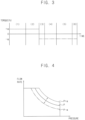
- FIG. 2 is a block diagram illustrating a controller of the control system for the construction machinery in FIG. 1 .
- FIG. 3 is a graph illustrating a maximum absorbing torque of a hydraulic pump in a loading operation of an excavator in accordance with example embodiments.
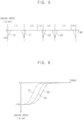
- FIG. 4 is a graph illustrating a constant horse power diagram according to a torque control of the hydraulic pump in the loading operation in FIG. 3 .
- FIG. 5 is a graph illustrating an engine speed control in the loading operation in FIG. 3 .
- FIG. 6 is graphs illustrating engine RPM curves according to a percent torque in the engine speed control in FIG. 5 .
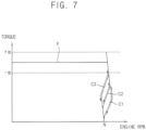
- FIG. 7 is graphs illustrating a torque diagram of an engine in the loading operation in FIG. 3 .
- a control system for construction machinery may include an engine 10 as an internal combustion engine, at least one hydraulic pump 20 driven by the engine 10, a control valve 30 configured to control a flow direction of a hydraulic oil discharged from the hydraulic pump 20 to control operations of actuators 40, and a control device configured to control operations of the engine 10 and the hydraulic pump 20 according to a subordinate work pattern being performed by the construction machinery.
- the construction machinery may include an excavator, a wheel loader, a forklift, etc.
- an excavator a wheel loader
- a forklift a forklift
- example embodiments may be applied to the excavator.
- it may not be limited thereto, and it may be understood that example embodiments may be applied to other construction machinery such as the wheel loader, the forklift, etc.
- the construction machinery may include a lower travelling body, an upper swinging body mounted to be capable of swinging on the lower travelling body, and a cabin and a front working device installed in the upper swinging body.
- the front working device may include a boom, an arm and a bucket.
- the actuator 40 may include a boom cylinder installed between the boom and the upper swinging body to control a movement of the boom, an arm cylinder installed between the arm and the boom to control a movement of the arm, a bucket cylinder installed between the bucket and the arm to control a movement of the bucket, a swing motor installed between the upper swinging body and the lower travelling body to control the upper swing body, etc.
- the engine 10 may include a diesel engine as a driving source of the construction machinery such as an excavator.
- a torque control of the engine 10 may be performed by adjusting an amount of fuel injected into a cylinder of the engine 10.
- a fuel injection device 12 may be controlled to adjust the amount of the fuel based on an inputted control signal.
- the hydraulic pump 20 may be connected to an output axis of the engine 10, and as the output axis of the engine rotates, the hydraulic pump 20 may be driven to discharge the hydraulic oil.
- the hydraulic pump 20 may include a variable capacity hydraulic pump.
- a discharge flow rate of the hydraulic pump 20 may be determined by a swash plate angle.
- the angle of the swash plate of the hydraulic pump 20 may be adjusted by a pump regulator 22.
- An electronic proportional control valve may be provided in the pump regulator 22 to control the discharge flow rate of the hydraulic pump 20 based on the inputted control signal.
- the hydraulic oil discharged from the hydraulic pump 20 may be supplied to the control valve 30, and if a specific spool of the control valve 30 is operated, the hydraulic oil may be supplied to the actuator 40 associated with the spool.
- the control system for the construction machinery may include a main control valve (MCV) as an assembly including the control valve 30.
- the main control valve may be an electro-hydraulic main control valve including an electro proportional pressure reducing valve (EPPRV) which controls a pilot working oil supplied to the spool of the control valve according to an inputted electrical signal.
- EPPRV electro proportional pressure reducing valve
- the main control valve may include a hydraulic control valve controlled by a pilot pressure proportional to a manipulation signal.
- An operator may manipulate a joystick, a pedal, etc. provided in a manipulation portion 50 to generate a manipulation signal proportional to a manipulation amount.
- the manipulation portion 50 may generate a flow rate control signal (pilot pressure) via a pilot hydraulic oil according to the manipulation amount.
- the flow rate control signal may be supplied to the control valve 30.
- control device of the construction machinery may include an engine control unit (ECU) 70, a controller 100, various sensors 200 and a setter 60, and may perform appropriate control according to a desired operation item by the operator.
- ECU engine control unit
- a monitor panel serving as the setter 60 for selecting a desired power mode by an operator may be installed in a cabin.
- the power mode may represent an output ratio of the engine and the hydraulic pump, that is, an absorbing torque (limit torque) value of the hydraulic pump.
- a mode, P+ mode, P mode, S mode, and E mode may be provided as the operation item of the power mode.
- the output ratio of the engine and the hydraulic pump, that is, an initial absorbing torque value of the hydraulic pump may be set according to the mode (P+ mode, P mode, S mode, and E mode) directly selected by the operator.
- the controller 100 may include a data receiver 110, a subordinate work determiner 120 and an output portion 130.
- the output portion 130 may include an engine control signal output portion 132 and a pump control signal output portion 134.
- the data receiver 110 may receive signals necessary for determining a work pattern (subordinate work, sub work) currently being performed by the construction machinery. For example, the data receiver 110 may receive a joystick displacement amount as the manipulation signal from the manipulation unit 60. The data receiver 110 may receive a discharge pressure of the hydraulic pump 20 from a pump pressure sensor 200. The data receiver 110 may receive a power mode setting signal from the setter 60.
- the subordinate work determiner 120 may determine a current subordinate work (sub work pattern) by using data from the data receiver 110.
- the subordinate work determiner 120 may normalize the data and perform a machine learning algorithm to determine the current subordinate work.
- the output portion 130 may output control signals for controlling the engine 10 and the hydraulic pump 20 determined according to the current subordinate work.
- the engine control signal output portion 132 nay output an engine speed control signal determined according to the current subordinate work to the engine control unit 70, and the engine control unit 70 may control the fuel injection device 12 of the engine 10.
- the fuel injection device 12 may adjust the amount of the fuel based on the inputted engine speed control signal to control the engine speed (RPM).
- the pump control signal output portion 134 may output a hydraulic pump control signal determined according to the current subordinate work to the pump regulator 22.
- the pump regulator 22 may adjust the swash plate angle of the hydraulic pump 20 based on the inputted hydraulic pump control signal to control the discharge flow rate.
- the subordinate work determiner 120 may divide the current subordinate work into a plurality of load areas, for example, a heavy load area, a middle load area, and a low load area according to an amount of load, and the output portion 130 may control an absorbing torque of the hydraulic pump 20 according to the load area and may control an increase/decrease rate (change rate) of the engine speed (engine speed change map) according to the torque of the engine 20.
- the pump control signal output portion 134 may output a first pump control signal to the pump regulator 22 to have a first maximum absorbing torque that is increased by a first ratio from the initial absorbing torque value when the current subordinate work is in a high load area, and may output a second pump control signal to the pump regulator 22 to have a second maximum absorbing torque which is decreased by a second ratio from the initial absorbing torque value when the current subordinate work is in a low load area.
- the loading operation may be divided into a digging work (1), a boom raising and swing work (2), a single swing work (3), a dump work (4), a single swing work (5) and a boom lowering work (6) as the subordinate works.
- the initial absorbing torque value P of the hydraulic pump 20 may be set.
- the boom raising and swinging work (2) or the pump control signal output portion 134 may output a first pump control signal to the pump regulator 22 to have a first absorbing torque value which is increased by a first ratio ( ⁇ %) from the initial absorbing torque value P.
- the pump control signal output portion 134 may output a second pump control signal to the pump regulator 22 to have a second absorbing torque value which is decreased by a second ratio (- ⁇ %) from the initial absorbing torque value P.
- the constant power (horsepower) diagram of the hydraulic pump 20 may be changed.
- the discharge flow rate of the hydraulic pump 20 according to the first pump control signal may be controlled to be greater than the discharge flow rate of the hydraulic pump 20 according to the second pump control signal.
- a torque value of a high power level may be applied to the digging work (1) and the boom raising and swing work (2), which are in the high load area, and a torque value of a low power level may be applied to the single swing work (3, 5), the dump work (4), and the boom lowering work (6), which are in the low load area.
- productivity in the high load area may be improved, and torque in the low load area may be limited to suppress fuel consumption, which may be unnecessarily generated by pulsed disturbance.
- the operator does not need to manually set the power mode every time, and may perform high productivity work of the high power mode even in the low power mode.
- it may be possible to recognize a work situation requiring a reduction in cycle time and change the torque limit value according to the corresponding situation.
- the engine control signal output unit 132 may output a first engine speed control signal to the engine control unit 70 to have a first engine speed change rate in high-speed control (engine speed control in a high rpm range) when the current subordinate work requires a high working speed, may output a second engine speed control signal to the engine control unit 70 to have a second engine speed change rate less than the first engine speed change rate in high-speed control when the current subordinate work requires a relatively middle speed, and may output a third engine speed control signal to the engine control unit 70 to have a third engine speed change rate less than the second engine speed change rate in high-speed control when the current subordinate work requires a slow speed.
- graph 1 (C1) shows an engine rpm profile according to a percent torque when the first engine speed change rate is provided in high-speed control of the engine 20
- graph 2 (C2) shows an engine rpm profile according to a percent torque when the second engine speed change is provided in high-speed control of the engine 20
- graph 3(C3) shows an engine rpm profile according to a percent torque when the third engine speed change rate is provided in high-speed control of the engine 20.
- An operator may manipulate a fuel dial to set a target engine speed.
- a high-speed control region in which an engine load and an engine torque are matched each other may be set according to the target engine speed. For example, by manipulating the fuel dial, any one of a first high speed control region including a maximum rated power (horsepower) point and a second high speed control region defined in a relatively low speed section may be selected as the high-speed control region.
- the engine speed when the first engine speed control signal is output to have the first engine speed change rate in the selected one high-speed control region, the engine speed may be controlled to increase along graph 1 (C1) from an initial operation ideal rotation speed (No) as the engine torque increases.
- the engine speed When the second engine speed control signal is output to have the second engine speed change rate in the high-speed control region, the engine speed may be controlled to increase along graph 2 (C2) from the initial operation ideal rotation speed (No) as the engine torque increases.
- the third engine speed control signal is output to have the third engine speed change rate in the high-speed control region, the engine speed may be controlled to increase along graph 3 (C3) from an initial operation ideal rotation speed (No) as the engine torque increases.
- the first engine speed change rate (C1) in which rpm increases relatively fast may be applied to improve productivity.
- the third engine speed change rate (C3) may be applied such that the work is performed for a relatively long time in a rpm region with good fuel economy (-100rpm) to improve fuel efficiency.
- an optimized rpm profile curve may be applied for each subordinate work, to thereby improve fuel economy and productivity together.
- the rpm change rate may be minimized to thereby improve workability, and in an excavating or loading work that requires a fast work the rpm change rate may be maximized to quickly follow a required operation to thereby reduce working time and fuel economy.
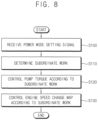
- FIG. 8 is a flow chart illustrating a control method for construction machinery in accordance with example embodiments.
- a setting signal of a power mode may be received (S 100), and a current subordinate work (detailed work) of the construction machinery nay be determined (S110).
- an operator may select a specific power mode through a setter 60, and a data receiver 110 of a controller 100 may receive the power mode setting signal from the setter 60.
- a mode, P+ mode, P mode, S mode, and E mode may be provided as an operation item of the power mode.
- An output ratio of an engine and a hydraulic pump, that is, an initial absorbing torque value of the hydraulic pump 20 may be determined according to the mode (P+ mode, P mode, S mode, and E mode) directly selected by the operator.
- signals necessary for determining a subordinate work (detailed work) currently being performed by the construction machinery may be received from various sensors, and a current subordinate work may be determined based thereon.
- An operator may manipulate a manipulation portion 50 for a specific work, and the data receiver 110 of the controller 100 may receive manipulation signals for actuators 40, for example, a joystick displacement amount, a joystick pilot pressure, etc. from the manipulation portion 50. Additionally, the data receiver 110 may receive a discharge pressure of the hydraulic pump 20 from a pump pressure sensor 200.
- a subordinate work determiner 120 of the controller 100 may determine a current subordinate work by using data from the data receiver 110.
- the subordinate work determiner 120 may normalize the data and perform a machine learning algorithm to determine the current subordinate work.
- the subordinate work determiner 120 may divide the current subordinate work into a plurality of load areas, for example, a heavy load area, a middle load area, and a low load area according to an amount of load. Additionally, the subordinate work determiner 120 may divide the current subordinate work into a plurality of work speed regions, for example, a fast work speed region, a middle work speed region and a slow work speed region according to a work speed.
- a torque of the hydraulic pump 20 may be controlled according to the determined subordinate work (S120), and an engine rotation speed change map (engine speed change rate) in high-speed region may be controlled according to the determined subordinate work (S130).
- the hydraulic pump 20 may be controlled to have a maximum absorbing torque that is increased or decreased by a preset ratio from an initial absorbing torque value according to the load amount of the current subordinate work.
- the initial absorbing torque value may be determined by the power mode selected by the operator.
- a pump control signal output portion 134 of the controller 130 may output a first pump control signal to a pump regulator 22 to have a first maximum absorbing torque that is increased by a first ratio from the initial absorbing torque value when the current subordinate work is in a high load area.
- the pump regulator 22 may adjust a swash plate angle of the hydraulic pump 20 according to the first pump control signal such that the hydraulic pump 20 is controlled to have the first maximum absorption torque as the maximum absorbing torque.
- the pump control signal output portion 134 of the controller 130 may output a second pump control signal to the pump regulator 22 to have a second maximum absorbing torque that is decreased by a second ratio from the initial absorbing torque value when the current subordinate work is in a low load area.
- the pump regulator 22 may adjust the swash plate angle of the hydraulic pump 20 according to the second pump control signal such that the hydraulic pump 20 is controlled to have the second maximum absorption torque as the maximum absorbing torque.
- the pump control signal output portion 134 of the controller 130 may output a third pump control signal to the pump regulator 22 to have a third maximum absorbing torque that is less than the first maximum absorbing torque and greater than the second maximum absorbing torque, for example, the initial absorbing torque value when the current subordinate work is in a middle load area.
- the pump regulator 22 may adjust the swash plate angle of the hydraulic pump 20 according to the third pump control signal such that the hydraulic pump 20 is controlled to have the third maximum absorption torque as the maximum absorbing torque.
- the maximum absorbing torque of the hydraulic pump 20 may be set to a value which is increased by a first ratio ( ⁇ %) from an initial absorbing torque value P.
- the maximum absorbing torque of the hydraulic pump 20 may be set to a value which is decreased by a second ratio (- ⁇ %) from the initial absorbing torque value P.
- an engine speed change map (engine speed change rate) in high-speed control may be controlled according to a current working speed of the subordinate work.
- an initial engine speed change rate in high-speed control may be determined by a fuel dial set value preset by an operator.
- an engine control signal output portion 132 of the controller 130 may output a first engine speed control signal to an engine control unit 70 to have a first engine speed change rate greater than the initial engine speed change rate in high-speed control when the current subordinate work has a high working speed.
- the engine control unit 70 may control a fuel injection amount of a fuel injection device 12 according to the first engine speed control signal.
- the engine control signal output portion 132 of the controller 130 may output a second engine speed control signal to the engine control unit 70 to have a second engine speed change rate less than the initial engine speed change rate in high-speed control when the current subordinate work has a slow working speed.
- the engine control unit 70 may control the fuel injection amount of the fuel injection device 12 according to the second engine speed control signal.
- the engine speed change rate in high-speed control may be determined as a first engine speed change rate (C1) greater than the initial engine speed change rate.
- the engine speed change rate in high-speed control may be determined as a second engine speed change rate (C3) less than the initial engine speed change rate.
- the engine speed change rate in high-speed control may be determined as a third engine speed change rate (C2) less than the first engine speed rate C1 and greater than the second engine speed change rate C3, for example, the initial engine speed change rate.
- the optimized maximum absorbing torque of the hydraulic pump 20 and the optimized engine speed change map (engine speed change rate) may be applied according to the current work situation (load amount, working speed).
- the current work situation load amount, working speed.
Description
- Example embodiments relate to a control method for construction machinery and a control system for construction machinery. More particularly, example embodiments relate to a method of controlling an engine and a hydraulic pump in construction machinery such as an excavator and a control system for construction machinery for performing the same.
- In general, construction machinery such as an excavator may include an engine as a prime mover, and may drive at least one variable capacity hydraulic pump using the engine such that a hydraulic actuator is driven by a hydraulic oil discharged from the hydraulic pump to perform a necessary operation.
- When an operator directly determines and selects a power mode of the hydraulic pump in consideration of working situations, the operator may select a power mode suitable for a maximum load condition. However, when only part of the repetitive detailed work content is in a high load area and most of the rest is in a low load area, unnecessary energy may be consumed and fuel economy may be deteriorated.
- Further, in high-speed control, an engine speed profile curve that changes according to a load may be used fixedly. In this case, there is a problem in that workability and operability may be deteriorated when a work speed required by the current work changes.
US 6 308 516 B1 describes a control device for hydraulically operated equipment. - Example embodiments provide a control method for construction machinery capable of improving fuel efficiency and workability together.
- Example embodiments provide a control system for construction machinery for performing the same.
- According to example embodiments, in a control method for construction machinery, an operation performed by the construction machinery is divided into a plurality of subordinate works. A current subordinate work currently performed by the construction machinery is determined. A maximum absorbing torque of a hydraulic pump is adjusted according to the determined subordinate work. An engine speed change map is adjusted according to the determined subordinate work.
- In example embodiments, adjusting the maximum absorbing torque of the hydraulic pump may include controlling the hydraulic pump to have a maximum absorbing torque that is increased or decreased by a preset ratio from an initial absorbing torque value according to a load amount of the current subordinate work.
- In example embodiments, the initial absorbing torque value may be determined by a power mode selected by an operator.
- In example embodiments, adjusting the maximum absorbing torque of the hydraulic pump may include controlling the hydraulic pump to have a first maximum absorbing torque that is increased by a first ratio from the initial absorbing torque value when the current subordinate work is in a high load area, and controlling the hydraulic pump to have a second maximum absorbing torque that is decreased by a second ratio from the initial absorbing torque value when the current subordinate work is in a low load area.
- In example embodiments, adjusting the maximum absorbing torque of the hydraulic pump may further include controlling to have a third maximum absorbing torque that is less than the first maximum absorbing torque value and greater than the second maximum absorbing torque value when the current subordinate work is in a middle load area.
- In example embodiments, adjusting the engine speed change map may include controlling an engine to have an engine speed change rate that is increased or decreased by a preset ratio from an initial engine speed change rate in high-speed control according to a required working speed of the current subordinate work.
- In example embodiments, the initial engine speed change rate may be determined by a fuel dial set value preset by an operator.
- In example embodiments, adjusting the engine speed change map may include controlling the engine to have a first engine speed change rate in high-speed control when the current subordinate work has a first required working speed, and controlling the engine to have a second engine speed change rate less than the first engine speed change rate in high-speed control when the current subordinate work has a second required working speed less than the first required working speed.
- According to example embodiments, a control system for construction machinery is provided. The construction machinery includes an engine, a hydraulic pump driven by the engine and a control valve configured to control a flow direction of a hydraulic oil discharged from the hydraulic pump to control operations of actuators. The control system includes a controller configured to determine a current subordinate work of the construction machinery and output a pump control signal and an engine control signal according to the determined current subordinate work, a pump regulator configured to adjust a swash plate angle of the hydraulic pump to have a maximum absorbing torque corresponding to the pump control signal, and an engine control unit configured to adjust an engine rpm to have an engine speed change map corresponding to the engine control signal.
- In example embodiments, the controller may control the swash plate angle of the hydraulic pump to have the maximum absorbing torque that is increased or decreased by a preset ratio from an initial absorbing torque value of the hydraulic pump according to a load amount of the current subordinate work.
- In example embodiments, the initial absorbing torque value may be determined by a power mode selected by an operator.
- In example embodiments, the controller may output a first pump control signal to have a first maximum absorbing torque that is increased by a first ratio from the initial absorbing torque value when the current subordinate work is in a high load area, and the controller may output a second pump control signal to have a second maximum absorbing torque that is decreased by a second ratio from the initial absorbing torque value when the current subordinate work is in a low load area.
- In example embodiments, the controller may output a third pump control signal to have a third maximum absorbing torque that is less than the first maximum absorbing torque value and greater than the second maximum absorbing torque value when the current subordinate work is in a middle load area.
- In example embodiments, the controller may control the engine to have an engine speed change rate that is increased or decreased by a preset ratio from an initial engine speed change rate in high-speed control according to a required working speed of the current subordinate work.
- In example embodiments, the initial engine speed change rate may be determined by a fuel dial set value preset by an operator.
- In example embodiments, the controller may output a first engine control signal to have a first engine speed change rate in high-speed control when the current subordinate work has a first required working speed, and the controller may output a second engine control signal to have a second engine speed change rate less than the first engine speed change rate in high-speed control when the current subordinate work has a second required working speed less than the first required working speed.
- According to example embodiments, an optimized maximum absorbing torque of a hydraulic pump and an optimized engine speed change map (engine speed change rate) in high-speed control may be applied according to a current work situation (load amount, working speed). Thus, fuel economy and productivity may be improved together.
- Example embodiments will be more clearly understood from the following detailed description taken in conjunction with the accompanying drawings.
-
FIG. 1 is a hydraulic diagram illustrating a control system for construction machinery in accordance with example embodiments. -
FIG. 2 is a block diagram illustrating a controller of the control system for the construction machinery inFIG. 1 . -
FIG. 3 is a graph illustrating a maximum absorbing torque of a hydraulic pump in a loading operation of an excavator in accordance with example embodiments. -
FIG. 4 is a graph illustrating a constant horse power diagram according to a torque control of the hydraulic pump in the loading operation inFIG. 3 . -
FIG. 5 is a graph illustrating an engine speed control in the loading operation inFIG. 3 . -
FIG. 6 is graphs illustrating engine RPM curves according to a percent torque in the engine speed control inFIG. 5 . -
FIG. 7 is graphs illustrating a torque diagram of an engine in the loading operation inFIG. 3 . -
FIG. 8 is a flow chart illustrating a control method for construction machinery in accordance with example embodiments. - Hereinafter, preferable embodiments of the present invention will be explained in detail with reference to the accompanying drawings.
- In the drawings, the sizes and relative sizes of components or elements may be exaggerated for clarity.
- It will be understood that, although the terms first, second, third, etc. may be used herein to describe various elements, components, regions, layers and/or sections, these elements, components, regions, layers and/or sections should not be limited by these terms. These terms are only used to distinguish one element, component, region, layer or section from another element, component, region, layer or section. Thus, a first element, component, region, layer or section discussed below could be termed a second element, component, region, layer or section without departing from the teachings of example embodiments.
- The terminology used herein is for the purpose of describing particular example embodiments only and is not intended to be limiting of example embodiments. As used herein, the singular forms "a," "an" and "the" are intended to include the plural forms as well, unless the context clearly indicates otherwise. It will be further understood that the terms "comprises" and/or "comprising," when used in this specification, specify the presence of stated features, integers, steps, operations, elements, and/or components, but do not preclude the presence or addition of one or more other features, integers, steps, operations, elements, components, and/or groups thereof.
- Unless otherwise defined, all terms (including technical and scientific terms) used herein have the same meaning as commonly understood by one of ordinary skill in the art to which example embodiments belong. It will be further understood that terms, such as those defined in commonly used dictionaries, should be interpreted as having a meaning that is consistent with their meaning in the context of the relevant art and will not be interpreted in an idealized or overly formal sense unless expressly so defined herein.
- Example embodiments may, however, be embodied in many different forms and should not be construed as limited to example embodiments set forth herein. Rather, these example embodiments are provided so that this disclosure will be thorough and complete, and will fully convey the scope of example embodiments to those skilled in the art.
-
FIG. 1 is a hydraulic diagram illustrating a control system for construction machinery in accordance with example embodiments.FIG. 2 is a block diagram illustrating a controller of the control system for the construction machinery inFIG. 1 .FIG. 3 is a graph illustrating a maximum absorbing torque of a hydraulic pump in a loading operation of an excavator in accordance with example embodiments.FIG. 4 is a graph illustrating a constant horse power diagram according to a torque control of the hydraulic pump in the loading operation inFIG. 3 .FIG. 5 is a graph illustrating an engine speed control in the loading operation inFIG. 3 .FIG. 6 is graphs illustrating engine RPM curves according to a percent torque in the engine speed control inFIG. 5 .FIG. 7 is graphs illustrating a torque diagram of an engine in the loading operation inFIG. 3 . - Referring to
FIGS. 1 to 7 , a control system for construction machinery may include anengine 10 as an internal combustion engine, at least onehydraulic pump 20 driven by theengine 10, acontrol valve 30 configured to control a flow direction of a hydraulic oil discharged from thehydraulic pump 20 to control operations ofactuators 40, and a control device configured to control operations of theengine 10 and thehydraulic pump 20 according to a subordinate work pattern being performed by the construction machinery. - In example embodiments, the construction machinery may include an excavator, a wheel loader, a forklift, etc. Hereinafter, it will be explained that example embodiments may be applied to the excavator. However, it may not be limited thereto, and it may be understood that example embodiments may be applied to other construction machinery such as the wheel loader, the forklift, etc.
- The construction machinery may include a lower travelling body, an upper swinging body mounted to be capable of swinging on the lower travelling body, and a cabin and a front working device installed in the upper swinging body. The front working device may include a boom, an arm and a bucket. The
actuator 40 may include a boom cylinder installed between the boom and the upper swinging body to control a movement of the boom, an arm cylinder installed between the arm and the boom to control a movement of the arm, a bucket cylinder installed between the bucket and the arm to control a movement of the bucket, a swing motor installed between the upper swinging body and the lower travelling body to control the upper swing body, etc. - In example embodiments, the
engine 10 may include a diesel engine as a driving source of the construction machinery such as an excavator. A torque control of theengine 10 may be performed by adjusting an amount of fuel injected into a cylinder of theengine 10. Afuel injection device 12 may be controlled to adjust the amount of the fuel based on an inputted control signal. - In example embodiments, the
hydraulic pump 20 may be connected to an output axis of theengine 10, and as the output axis of the engine rotates, thehydraulic pump 20 may be driven to discharge the hydraulic oil. Thehydraulic pump 20 may include a variable capacity hydraulic pump. A discharge flow rate of thehydraulic pump 20 may be determined by a swash plate angle. The angle of the swash plate of thehydraulic pump 20 may be adjusted by apump regulator 22. An electronic proportional control valve may be provided in thepump regulator 22 to control the discharge flow rate of thehydraulic pump 20 based on the inputted control signal. - The hydraulic oil discharged from the
hydraulic pump 20 may be supplied to thecontrol valve 30, and if a specific spool of thecontrol valve 30 is operated, the hydraulic oil may be supplied to theactuator 40 associated with the spool. For example, the control system for the construction machinery may include a main control valve (MCV) as an assembly including thecontrol valve 30. The main control valve may be an electro-hydraulic main control valve including an electro proportional pressure reducing valve (EPPRV) which controls a pilot working oil supplied to the spool of the control valve according to an inputted electrical signal. Alternatively, the main control valve may include a hydraulic control valve controlled by a pilot pressure proportional to a manipulation signal. - An operator may manipulate a joystick, a pedal, etc. provided in a
manipulation portion 50 to generate a manipulation signal proportional to a manipulation amount. For example, themanipulation portion 50 may generate a flow rate control signal (pilot pressure) via a pilot hydraulic oil according to the manipulation amount. The flow rate control signal may be supplied to thecontrol valve 30. - In example embodiments, the control device of the construction machinery may include an engine control unit (ECU) 70, a
controller 100,various sensors 200 and asetter 60, and may perform appropriate control according to a desired operation item by the operator. - A monitor panel serving as the
setter 60 for selecting a desired power mode by an operator may be installed in a cabin. The power mode may represent an output ratio of the engine and the hydraulic pump, that is, an absorbing torque (limit torque) value of the hydraulic pump. - A mode, P+ mode, P mode, S mode, and E mode may be provided as the operation item of the power mode. The output ratio of the engine and the hydraulic pump, that is, an initial absorbing torque value of the hydraulic pump may be set according to the mode (P+ mode, P mode, S mode, and E mode) directly selected by the operator.
- In example embodiments, the
controller 100 may include adata receiver 110, asubordinate work determiner 120 and anoutput portion 130. Theoutput portion 130 may include an engine controlsignal output portion 132 and a pump controlsignal output portion 134. - The
data receiver 110 may receive signals necessary for determining a work pattern (subordinate work, sub work) currently being performed by the construction machinery. For example, thedata receiver 110 may receive a joystick displacement amount as the manipulation signal from themanipulation unit 60. Thedata receiver 110 may receive a discharge pressure of thehydraulic pump 20 from apump pressure sensor 200. Thedata receiver 110 may receive a power mode setting signal from thesetter 60. - The
subordinate work determiner 120 may determine a current subordinate work (sub work pattern) by using data from thedata receiver 110. Thesubordinate work determiner 120 may normalize the data and perform a machine learning algorithm to determine the current subordinate work. - The
output portion 130 may output control signals for controlling theengine 10 and thehydraulic pump 20 determined according to the current subordinate work. The engine controlsignal output portion 132 nay output an engine speed control signal determined according to the current subordinate work to theengine control unit 70, and theengine control unit 70 may control thefuel injection device 12 of theengine 10. Thefuel injection device 12 may adjust the amount of the fuel based on the inputted engine speed control signal to control the engine speed (RPM). The pump controlsignal output portion 134 may output a hydraulic pump control signal determined according to the current subordinate work to thepump regulator 22. Thepump regulator 22 may adjust the swash plate angle of thehydraulic pump 20 based on the inputted hydraulic pump control signal to control the discharge flow rate. - In particular, the
subordinate work determiner 120 may divide the current subordinate work into a plurality of load areas, for example, a heavy load area, a middle load area, and a low load area according to an amount of load, and theoutput portion 130 may control an absorbing torque of thehydraulic pump 20 according to the load area and may control an increase/decrease rate (change rate) of the engine speed (engine speed change map) according to the torque of theengine 20. - As illustrated in
FIGS. 3 and 4 , the pump controlsignal output portion 134 may output a first pump control signal to thepump regulator 22 to have a first maximum absorbing torque that is increased by a first ratio from the initial absorbing torque value when the current subordinate work is in a high load area, and may output a second pump control signal to thepump regulator 22 to have a second maximum absorbing torque which is decreased by a second ratio from the initial absorbing torque value when the current subordinate work is in a low load area. - For example, when the excavator performs a loading operation, the loading operation may be divided into a digging work (1), a boom raising and swing work (2), a single swing work (3), a dump work (4), a single swing work (5) and a boom lowering work (6) as the subordinate works.
- When the operator selects the P mode, the initial absorbing torque value P of the
hydraulic pump 20 may be set. In this case, when the current subordinated work is the digging work (1), the boom raising and swinging work (2) or the pump controlsignal output portion 134 may output a first pump control signal to thepump regulator 22 to have a first absorbing torque value which is increased by a first ratio (α%) from the initial absorbing torque value P. When the current subordinated work is the single swing work (3, 5), the dump work (4) or the boom lowering work (6), the pump controlsignal output portion 134 may output a second pump control signal to thepump regulator 22 to have a second absorbing torque value which is decreased by a second ratio (-α%) from the initial absorbing torque value P. - As the first pump control signal and the second pump control signal are inputted to the
pump regulator 22, the constant power (horsepower) diagram of thehydraulic pump 20 may be changed. In case of the same external load (pressure), the discharge flow rate of thehydraulic pump 20 according to the first pump control signal may be controlled to be greater than the discharge flow rate of thehydraulic pump 20 according to the second pump control signal. - A torque value of a high power level may be applied to the digging work (1) and the boom raising and swing work (2), which are in the high load area, and a torque value of a low power level may be applied to the single swing work (3, 5), the dump work (4), and the boom lowering work (6), which are in the low load area.
- Thus, productivity in the high load area may be improved, and torque in the low load area may be limited to suppress fuel consumption, which may be unnecessarily generated by pulsed disturbance. Further, the operator does not need to manually set the power mode every time, and may perform high productivity work of the high power mode even in the low power mode. Moreover, even for other operating situations that are not included in the 180 degree loading operation, it may be possible to recognize a work situation requiring a reduction in cycle time and change the torque limit value according to the corresponding situation.
- As illustrated in
FIGS. 5 and 6 , the engine controlsignal output unit 132 may output a first engine speed control signal to theengine control unit 70 to have a first engine speed change rate in high-speed control (engine speed control in a high rpm range) when the current subordinate work requires a high working speed, may output a second engine speed control signal to theengine control unit 70 to have a second engine speed change rate less than the first engine speed change rate in high-speed control when the current subordinate work requires a relatively middle speed, and may output a third engine speed control signal to theengine control unit 70 to have a third engine speed change rate less than the second engine speed change rate in high-speed control when the current subordinate work requires a slow speed. - In
FIG. 6 , graph 1 (C1) shows an engine rpm profile according to a percent torque when the first engine speed change rate is provided in high-speed control of theengine 20, graph 2 (C2) shows an engine rpm profile according to a percent torque when the second engine speed change is provided in high-speed control of theengine 20, and graph 3(C3) shows an engine rpm profile according to a percent torque when the third engine speed change rate is provided in high-speed control of theengine 20. - An operator may manipulate a fuel dial to set a target engine speed. A high-speed control region in which an engine load and an engine torque are matched each other may be set according to the target engine speed. For example, by manipulating the fuel dial, any one of a first high speed control region including a maximum rated power (horsepower) point and a second high speed control region defined in a relatively low speed section may be selected as the high-speed control region.
- As illustrated in
FIG. 7 , when the first engine speed control signal is output to have the first engine speed change rate in the selected one high-speed control region, the engine speed may be controlled to increase along graph 1 (C1) from an initial operation ideal rotation speed (No) as the engine torque increases. When the second engine speed control signal is output to have the second engine speed change rate in the high-speed control region, the engine speed may be controlled to increase along graph 2 (C2) from the initial operation ideal rotation speed (No) as the engine torque increases. When the third engine speed control signal is output to have the third engine speed change rate in the high-speed control region, the engine speed may be controlled to increase along graph 3 (C3) from an initial operation ideal rotation speed (No) as the engine torque increases. - For example, in the boom rising and swinging work (2) and the single swinging work (3) which requires a fast cycle time, the first engine speed change rate (C1) in which rpm increases relatively fast may be applied to improve productivity. On the other hand, in the dump work (4), the single swing work (5) and the boom lowering work (6) in which rpm increases relatively slowly and it is necessary to maintain a relatively long low rpm in a low load area, the third engine speed change rate (C3) may be applied such that the work is performed for a relatively long time in a rpm region with good fuel economy (-100rpm) to improve fuel efficiency. Thus, an optimized rpm profile curve may be applied for each subordinate work, to thereby improve fuel economy and productivity together.
- Further, by switching the engine rpm profile curve (engine rotation speed change map) according to various detailed work types (subordinate work type), in a leveling work that requires a delicate work the rpm change rate may be minimized to thereby improve workability, and in an excavating or loading work that requires a fast work the rpm change rate may be maximized to quickly follow a required operation to thereby reduce working time and fuel economy.
- Hereinafter, a method of controlling construction machinery using the control system in
FIG. 1 will be explained. -
FIG. 8 is a flow chart illustrating a control method for construction machinery in accordance with example embodiments. - Referring to
FIGS. 1 ,2 and8 , a setting signal of a power mode may be received (S 100), and a current subordinate work (detailed work) of the construction machinery nay be determined (S110). - In example embodiments, an operator may select a specific power mode through a
setter 60, and adata receiver 110 of acontroller 100 may receive the power mode setting signal from thesetter 60. - For example, a mode, P+ mode, P mode, S mode, and E mode may be provided as an operation item of the power mode. An output ratio of an engine and a hydraulic pump, that is, an initial absorbing torque value of the
hydraulic pump 20 may be determined according to the mode (P+ mode, P mode, S mode, and E mode) directly selected by the operator. - In example embodiments, signals necessary for determining a subordinate work (detailed work) currently being performed by the construction machinery may be received from various sensors, and a current subordinate work may be determined based thereon.
- An operator may manipulate a
manipulation portion 50 for a specific work, and thedata receiver 110 of thecontroller 100 may receive manipulation signals foractuators 40, for example, a joystick displacement amount, a joystick pilot pressure, etc. from themanipulation portion 50. Additionally, thedata receiver 110 may receive a discharge pressure of thehydraulic pump 20 from apump pressure sensor 200. - A
subordinate work determiner 120 of thecontroller 100 may determine a current subordinate work by using data from thedata receiver 110. Thesubordinate work determiner 120 may normalize the data and perform a machine learning algorithm to determine the current subordinate work. - The
subordinate work determiner 120 may divide the current subordinate work into a plurality of load areas, for example, a heavy load area, a middle load area, and a low load area according to an amount of load. Additionally, thesubordinate work determiner 120 may divide the current subordinate work into a plurality of work speed regions, for example, a fast work speed region, a middle work speed region and a slow work speed region according to a work speed. - Then, a torque of the
hydraulic pump 20 may be controlled according to the determined subordinate work (S120), and an engine rotation speed change map (engine speed change rate) in high-speed region may be controlled according to the determined subordinate work (S130). - In example embodiments, the
hydraulic pump 20 may be controlled to have a maximum absorbing torque that is increased or decreased by a preset ratio from an initial absorbing torque value according to the load amount of the current subordinate work. Here, the initial absorbing torque value may be determined by the power mode selected by the operator. - In particular, a pump control
signal output portion 134 of thecontroller 130 may output a first pump control signal to apump regulator 22 to have a first maximum absorbing torque that is increased by a first ratio from the initial absorbing torque value when the current subordinate work is in a high load area. Thepump regulator 22 may adjust a swash plate angle of thehydraulic pump 20 according to the first pump control signal such that thehydraulic pump 20 is controlled to have the first maximum absorption torque as the maximum absorbing torque. - The pump control
signal output portion 134 of thecontroller 130 may output a second pump control signal to thepump regulator 22 to have a second maximum absorbing torque that is decreased by a second ratio from the initial absorbing torque value when the current subordinate work is in a low load area. Thepump regulator 22 may adjust the swash plate angle of thehydraulic pump 20 according to the second pump control signal such that thehydraulic pump 20 is controlled to have the second maximum absorption torque as the maximum absorbing torque. - The pump control
signal output portion 134 of thecontroller 130 may output a third pump control signal to thepump regulator 22 to have a third maximum absorbing torque that is less than the first maximum absorbing torque and greater than the second maximum absorbing torque, for example, the initial absorbing torque value when the current subordinate work is in a middle load area. Thepump regulator 22 may adjust the swash plate angle of thehydraulic pump 20 according to the third pump control signal such that thehydraulic pump 20 is controlled to have the third maximum absorption torque as the maximum absorbing torque. - For example, when the excavator performs a loading operation, in case that the operator selects the P mode and the current subordinated work is the digging work (1) or the boom raising and swinging work (2), the maximum absorbing torque of the
hydraulic pump 20 may be set to a value which is increased by a first ratio (α%) from an initial absorbing torque value P. In case that the current subordinated work is the single swing work (3, 5), the dump work (4) or the boom lowering work (6), the maximum absorbing torque of thehydraulic pump 20 may be set to a value which is decreased by a second ratio (-α%) from the initial absorbing torque value P. - In example embodiments, an engine speed change map (engine speed change rate) in high-speed control may be controlled according to a current working speed of the subordinate work. Here, an initial engine speed change rate in high-speed control may be determined by a fuel dial set value preset by an operator.
- In particular, an engine control
signal output portion 132 of thecontroller 130 may output a first engine speed control signal to anengine control unit 70 to have a first engine speed change rate greater than the initial engine speed change rate in high-speed control when the current subordinate work has a high working speed. Theengine control unit 70 may control a fuel injection amount of afuel injection device 12 according to the first engine speed control signal. - The engine control
signal output portion 132 of thecontroller 130 may output a second engine speed control signal to theengine control unit 70 to have a second engine speed change rate less than the initial engine speed change rate in high-speed control when the current subordinate work has a slow working speed. Theengine control unit 70 may control the fuel injection amount of thefuel injection device 12 according to the second engine speed control signal. - For example, when an excavator performs a loading operation, in case that a current subordinate work is the boom raising and swing work (2) or the single swing work (3), the engine speed change rate in high-speed control may be determined as a first engine speed change rate (C1) greater than the initial engine speed change rate. In case that the current subordinate work is the dump work (4), the single swing work (5) or the boom lowering work (6), the engine speed change rate in high-speed control may be determined as a second engine speed change rate (C3) less than the initial engine speed change rate. In case that the current subordinate work is the digging work (1), the engine speed change rate in high-speed control may be determined as a third engine speed change rate (C2) less than the first engine speed rate C1 and greater than the second engine speed change rate C3, for example, the initial engine speed change rate.
- As mentioned above, the optimized maximum absorbing torque of the
hydraulic pump 20 and the optimized engine speed change map (engine speed change rate) may be applied according to the current work situation (load amount, working speed). Thus, fuel economy and productivity may be improved together.
Claims (16)
- A control method for construction machinery, the control method comprising:dividing an operation performed by the construction machinery into a plurality of subordinate works;determining a current subordinate work currently performed by the construction machinery;characterized in that,
the control method further comprises:adjusting a maximum absorbing torque of a hydraulic pump (20) according to the determined subordinate work; andadjusting an engine speed change map according to the determined subordinate work. - The control method of claim 1, wherein adjusting the maximum absorbing torque of the hydraulic pump (20) comprises controlling the hydraulic pump (20) to have a maximum absorbing torque that is increased or decreased by a preset ratio from an initial absorbing torque value according to a load amount of the current subordinate work.
- The control method of claim 2, wherein the initial absorbing torque value is determined by a power mode selected by an operator.
- The control method of claim 1, wherein adjusting the maximum absorbing torque of the hydraulic pump (20) comprisescontrolling the hydraulic pump (20) to have a first maximum absorbing torque that is increased by a first ratio from the initial absorbing torque value when the current subordinate work is in a high load area; andcontrolling the hydraulic pump (20) to have a second maximum absorbing torque that is decreased by a second ratio from the initial absorbing torque value when the current subordinate work is in a low load area.
- The control method of claim 4, wherein adjusting the maximum absorbing torque of the hydraulic pump (20) further comprises controlling to have a third maximum absorbing torque that is less than the first maximum absorbing torque value and greater than the second maximum absorbing torque value when the current subordinate work is in a middle load area.
- The control method of claim 1, wherein adjusting the engine speed change map comprises controlling an engine to have an engine speed change rate that is increased or decreased by a preset ratio from an initial engine speed change rate in high-speed control according to a required working speed of the current subordinate work.
- The control method of claim 6, wherein the initial engine speed change rate is determined by a fuel dial set value preset by an operator.
- The control method of claim 1, wherein adjusting the engine speed change map comprisescontrolling the engine to have a first engine speed change rate in high-speed control when the current subordinate work has a first required working speed; andcontrolling the engine to have a second engine speed change rate less than the first engine speed change rate in high-speed control when the current subordinate work has a second required working speed less than the first required working speed.
- A control system for construction machinery, the construction machinery including an engine, a hydraulic pump (20) driven by the engine and a control valve (30) configured to control a flow direction of a hydraulic oil discharged from the hydraulic pump (20) to control operations of actuators (40), the control system comprising:a controller (100) configured to determine a current subordinate work of the construction machinery and output a pump control signal and an engine control signal according to the determined current subordinate work;characterized in that,
the control system further comprises:a pump regulator (22) configured to adjust a swash plate angle of the hydraulic pump (20) to have a maximum absorbing torque corresponding to the pump control signal; andan engine control unit (70) configured to adjust an engine speed (RPM) to have an engine speed change map corresponding to the engine control signal. - The control system of claim 9, wherein the controller (100) controls the swash plate angle of the hydraulic pump (20) to have the maximum absorbing torque that is increased or decreased by a preset ratio from an initial absorbing torque value of the hydraulic pump (20) according to a load amount of the current subordinate work.
- The control system of claim 9, wherein the initial absorbing torque value is determined by a power mode selected by an operator.
- The control system of claim 9, wherein the controller (100) outputs a first pump control signal to have a first maximum absorbing torque that is increased by a first ratio from the initial absorbing torque value when the current subordinate work is in a high load area, and the controller (100) outputs a second pump control signal to have a second maximum absorbing torque that is decreased by a second ratio from the initial absorbing torque value when the current subordinate work is in a low load area.
- The control system of claim 12, wherein the controller (100) outputs a third pump control signal to have a third maximum absorbing torque that is less than the first maximum absorbing torque value and greater than the second maximum absorbing torque value when the current subordinate work is in a middle load area.
- The control system of claim 9, wherein the controller (100) controls the engine to have an engine speed change rate that is increased or decreased by a preset ratio from an initial engine speed change rate in high-speed control according to a required working speed of the current subordinate work.
- The control system of claim 14, wherein the initial engine speed change rate is determined by a fuel dial set value preset by an operator.
- The control system of claim 9, wherein the controller (100) outputs a first engine control signal to have a first engine speed change rate in high-speed control when the current subordinate work has a first required working speed, and the controller (100) outputs a second engine control signal to have a second engine speed change rate less than the first engine speed change rate in high-speed control when the current subordinate work has a second required working speed less than the first required working speed.
Applications Claiming Priority (1)
| Application Number | Priority Date | Filing Date | Title |
|---|---|---|---|
| KR1020200018383A KR20210103782A (en) | 2020-02-14 | 2020-02-14 | Control method for construction machinery and contorl system for construction machinery |
Publications (2)
| Publication Number | Publication Date |
|---|---|
| EP3865628A1 EP3865628A1 (en) | 2021-08-18 |
| EP3865628B1 true EP3865628B1 (en) | 2024-04-10 |
Family
ID=74591783
Family Applications (1)
| Application Number | Title | Priority Date | Filing Date |
|---|---|---|---|
| EP21156445.5A Active EP3865628B1 (en) | 2020-02-14 | 2021-02-11 | Control method for construction machinery and control system for construction machinery |
Country Status (4)
| Country | Link |
|---|---|
| US (1) | US11525242B2 (en) |
| EP (1) | EP3865628B1 (en) |
| KR (1) | KR20210103782A (en) |
| CN (1) | CN113266055B (en) |
Families Citing this family (1)
| Publication number | Priority date | Publication date | Assignee | Title |
|---|---|---|---|---|
| CN114263541B (en) * | 2021-12-29 | 2022-12-13 | 柳州柳工挖掘机有限公司 | Excavator control method and excavator |
Family Cites Families (8)
| Publication number | Priority date | Publication date | Assignee | Title |
|---|---|---|---|---|
| JP3874226B2 (en) * | 1998-04-24 | 2007-01-31 | 株式会社小松製作所 | Control device for hydraulic drive machine |
| JP3868112B2 (en) * | 1998-05-22 | 2007-01-17 | 株式会社小松製作所 | Control device for hydraulic drive machine |
| JP4163073B2 (en) * | 2003-08-12 | 2008-10-08 | 日立建機株式会社 | Control device for work vehicle |
| KR101637571B1 (en) * | 2009-12-23 | 2016-07-20 | 두산인프라코어 주식회사 | Hydraulic pump control apparatus and control method for construction machinery |
| JP5566333B2 (en) * | 2011-05-11 | 2014-08-06 | 日立建機株式会社 | Construction machine control system |
| JP5222975B2 (en) * | 2011-05-18 | 2013-06-26 | 株式会社小松製作所 | Engine control device for work machine and engine control method thereof |
| KR102015141B1 (en) * | 2013-03-29 | 2019-08-27 | 두산인프라코어 주식회사 | Control system and method of Hydraulic Pump for Construction Machinery |
| US20170037790A1 (en) * | 2014-04-15 | 2017-02-09 | Volvo Construction Equipment Ab | Device for controlling engine and hydraulic pump of construction equipment and control method therefor |
-
2020
- 2020-02-14 KR KR1020200018383A patent/KR20210103782A/en active Search and Examination
-
2021
- 2021-02-09 CN CN202110181177.6A patent/CN113266055B/en active Active
- 2021-02-11 EP EP21156445.5A patent/EP3865628B1/en active Active
- 2021-02-12 US US17/174,908 patent/US11525242B2/en active Active
Also Published As
| Publication number | Publication date |
|---|---|
| US11525242B2 (en) | 2022-12-13 |
| EP3865628A1 (en) | 2021-08-18 |
| CN113266055A (en) | 2021-08-17 |
| KR20210103782A (en) | 2021-08-24 |
| US20210254310A1 (en) | 2021-08-19 |
| CN113266055B (en) | 2022-10-04 |
Similar Documents
| Publication | Publication Date | Title |
|---|---|---|
| JP4675320B2 (en) | Hydraulic drive device for work machine | |
| JP4282718B2 (en) | Hydraulic drive device for hydraulic excavator | |
| JP5092060B1 (en) | Work vehicle and control method of work vehicle | |
| EP2215342B1 (en) | Process for electro-hydraulic circuits and systmes involving excavator boom-swing power management | |
| US11105348B2 (en) | System for controlling construction machinery and method for controlling construction machinery | |
| EP3865628B1 (en) | Control method for construction machinery and control system for construction machinery | |
| JP5736909B2 (en) | Pump controller for construction machinery | |
| US7607245B2 (en) | Construction machine | |
| KR100805990B1 (en) | Controller for hydraulic drive system | |
| JP6752686B2 (en) | Excavator | |
| JP3539720B2 (en) | Control equipment for construction machinery | |
| WO2017138070A1 (en) | Work vehicle and operation control method | |
| CN115516212A (en) | Hydraulic excavator driving system | |
| KR20140110859A (en) | Hydraulic machinery | |
| JP4381781B2 (en) | Pump controller for construction machinery | |
| US11946226B2 (en) | Work machine | |
| JP4376018B2 (en) | Control device for work vehicle | |
| JPH11324023A (en) | Engine control method for vehicle |
Legal Events
| Date | Code | Title | Description |
|---|---|---|---|
| PUAI | Public reference made under article 153(3) epc to a published international application that has entered the european phase |
Free format text: ORIGINAL CODE: 0009012 |
|
| STAA | Information on the status of an ep patent application or granted ep patent |
Free format text: STATUS: REQUEST FOR EXAMINATION WAS MADE |
|
| 17P | Request for examination filed |
Effective date: 20210211 |
|
| AK | Designated contracting states |
Kind code of ref document: A1 Designated state(s): AL AT BE BG CH CY CZ DE DK EE ES FI FR GB GR HR HU IE IS IT LI LT LU LV MC MK MT NL NO PL PT RO RS SE SI SK SM TR |
|
| RAP3 | Party data changed (applicant data changed or rights of an application transferred) |
Owner name: HYUNDAI DOOSAN INFRACORE CO., LTD. |
|
| RBV | Designated contracting states (corrected) |
Designated state(s): AL AT BE BG CH CY CZ DE DK EE ES FI FR GB GR HR HU IE IS IT LI LT LU LV MC MK MT NL NO PL PT RO RS SE SI SK SM TR |
|
| GRAP | Despatch of communication of intention to grant a patent |
Free format text: ORIGINAL CODE: EPIDOSNIGR1 |
|
| STAA | Information on the status of an ep patent application or granted ep patent |
Free format text: STATUS: GRANT OF PATENT IS INTENDED |
|
| INTG | Intention to grant announced |
Effective date: 20231106 |
|
| RAP3 | Party data changed (applicant data changed or rights of an application transferred) |
Owner name: HD HYUNDAI INFRACORE CO., LTD. |
|
| GRAS | Grant fee paid |
Free format text: ORIGINAL CODE: EPIDOSNIGR3 |
|
| GRAA | (expected) grant |
Free format text: ORIGINAL CODE: 0009210 |
|
| STAA | Information on the status of an ep patent application or granted ep patent |
Free format text: STATUS: THE PATENT HAS BEEN GRANTED |
|
| AK | Designated contracting states |
Kind code of ref document: B1 Designated state(s): AL AT BE BG CH CY CZ DE DK EE ES FI FR GB GR HR HU IE IS IT LI LT LU LV MC MK MT NL NO PL PT RO RS SE SI SK SM TR |
|
| RAP3 | Party data changed (applicant data changed or rights of an application transferred) |
Owner name: HD HYUNDAI INFRACORE CO., LTD. |
|
| REG | Reference to a national code |
Ref country code: GB Ref legal event code: FG4D |