EP0284815A2 - Plattenspieler - Google Patents
Plattenspieler Download PDFInfo
- Publication number
- EP0284815A2 EP0284815A2 EP88103301A EP88103301A EP0284815A2 EP 0284815 A2 EP0284815 A2 EP 0284815A2 EP 88103301 A EP88103301 A EP 88103301A EP 88103301 A EP88103301 A EP 88103301A EP 0284815 A2 EP0284815 A2 EP 0284815A2
- Authority
- EP
- European Patent Office
- Prior art keywords
- drive
- tray
- gear
- chassis
- disc player
- Prior art date
- Legal status (The legal status is an assumption and is not a legal conclusion. Google has not performed a legal analysis and makes no representation as to the accuracy of the status listed.)
- Granted
Links
- 230000007246 mechanism Effects 0.000 claims abstract description 45
- 230000005540 biological transmission Effects 0.000 claims description 13
- 230000002093 peripheral effect Effects 0.000 claims description 10
- 230000003287 optical effect Effects 0.000 claims description 2
- 239000007787 solid Substances 0.000 claims description 2
- 230000033458 reproduction Effects 0.000 description 17
- 230000007723 transport mechanism Effects 0.000 description 5
- 230000000452 restraining effect Effects 0.000 description 4
- 238000010276 construction Methods 0.000 description 3
- 230000000875 corresponding effect Effects 0.000 description 3
- 238000007599 discharging Methods 0.000 description 3
- 230000009471 action Effects 0.000 description 2
- 230000008859 change Effects 0.000 description 2
- 230000004044 response Effects 0.000 description 2
- 230000003247 decreasing effect Effects 0.000 description 1
- 238000012840 feeding operation Methods 0.000 description 1
- 238000000034 method Methods 0.000 description 1
- 230000000717 retained effect Effects 0.000 description 1
- 238000004904 shortening Methods 0.000 description 1
- 230000032258 transport Effects 0.000 description 1
Images


Classifications
-
- G—PHYSICS
- G11—INFORMATION STORAGE
- G11B—INFORMATION STORAGE BASED ON RELATIVE MOVEMENT BETWEEN RECORD CARRIER AND TRANSDUCER
- G11B19/00—Driving, starting, stopping record carriers not specifically of filamentary or web form, or of supports therefor; Control thereof; Control of operating function ; Driving both disc and head
- G11B19/02—Control of operating function, e.g. switching from recording to reproducing
-
- G—PHYSICS
- G11—INFORMATION STORAGE
- G11B—INFORMATION STORAGE BASED ON RELATIVE MOVEMENT BETWEEN RECORD CARRIER AND TRANSDUCER
- G11B17/00—Guiding record carriers not specifically of filamentary or web form, or of supports therefor
- G11B17/02—Details
- G11B17/04—Feeding or guiding single record carrier to or from transducer unit
- G11B17/05—Feeding or guiding single record carrier to or from transducer unit specially adapted for discs not contained within cartridges
- G11B17/053—Indirect insertion, i.e. with external loading means
- G11B17/056—Indirect insertion, i.e. with external loading means with sliding loading means
-
- G—PHYSICS
- G11—INFORMATION STORAGE
- G11B—INFORMATION STORAGE BASED ON RELATIVE MOVEMENT BETWEEN RECORD CARRIER AND TRANSDUCER
- G11B17/00—Guiding record carriers not specifically of filamentary or web form, or of supports therefor
Definitions
- the present invention relates to a disc player for use with a plurality of discs having signals recorded thereon for selecting one of the discs and reproducing the recorded signals therefrom, and more particularly to a disc player having a drive mechanism for raising a signal reproduction unit to the position where the disc to be played is accommodated.
- Disc players heretofore known include those wherein a tray box is removably mounted on the main chassis of the player main body.
- the tray box has accommodated therein a plurality discs as individually placed on trays arranged in a multiplicity of stages.
- the desired one of the discs is horizontally withdrawn from the tray box along with the tray and set in the signal reproduction unit within the player main body.
- the reproduction unit including a turntable and a pickup is raised to the level of the withdrawn disc and reproduces the signals at this level.
- Fig. 21 shows a drive mechanism proposed for raising the reproduction unit to a specified level (Unexamined Japanese Patent Publication SHO 61-261851).
- This mechanism comprises a lift chassis 5 having the reproduction unit (not shown).
- the lift chassis 5 is movable upward and downward stepwise, whereby the reproduction unit is positioned as opposed to the desired disc D within a tray box 27.
- the lift chassis 5 is driven by drive slides 109 formed with steplike slanting grooves 110, 110.
- the lift chassis 5 is accommodated in a main chassis 1 with vertical grooves 112, 112 formed in its side plates.
- Each drive slide 109 is disposed along the side plate, and the slanting groove 110 includes horizontal portions and slanting portions.
- Each of pins 6, 6 projecting from the side plate of the lift chassis 5 is inserted through the vertical groove 112 and the slanting groove 110 at the intersection thereof. Accordingly, when the drive slides 109 are moved rightward or leftward by driving a motor 111, the pins 6 are pushed by the slanting grooved portions 110 of the drive slides 109, whereby the lift chassis 5 is moved stepwise upward or downward.
- the slanting groove 110 comprises the horizontal and slanting portions and has a zigzag shape to render the lift chassis 5 properly positionable at rest at different levels.
- the above mechanism therefore has the problem that when the pin 6 shifts from the horizontal portion to the slanting portion with the movement of the drive slide 109, the motor 111 is subjected to an abruptly increased load, failing to smoothly move the lift chassis 5.
- the horizontal portions, included in the slanting groove 110 and not contributing to the ascent or descent of the lift chassis 5, give an increased horizontal dimension to the drive slide 109 and add to the stroke length of the drive slide 109.
- the mechanism therefore has the problem of making the disc player large-sized.
- the main object of the present invention is to provide a disc player which comprises a drive slide having a straight slanting groove so as to render the lift chassis smoothly movable and in which the lift chassis is nevertheless properly retainable at the level of the desired one of discs arranged in a multiplicity of stages, the drive slide having a decreased dimension in the direction of its sliding movement to give the player a smaller dimension in the same direction.
- the present invention provides a disc player which comprises a lift chassis 5 liftably supported on a main chassis 1 and having a signal reproduction unit 31 mounted thereon, and a drive slide 9 supported by the main chassis 1 and movable in a direction intersecting the direction of movement of the lift chassis 5.
- the drive slide 9 is formed with a straight cam portion in engagement with a cam follower provided on the lift chassis 5 for driving the lift chassis 5 upward or downward.
- An intermittent feed mechanism is provided between the drive slide 9 and a motor 23 for reciprocatingly moving the drive slide.
- the intermittent feed mechanism comprises a drive portion for receiving a torque directly from the motor, and a driven portion to be intermittently driven by the drive portion while the drive portion is in continuous rotation.
- the power given to the driven portion is delivered to the drive slide to thereby move the drive slide stepwise.
- the drive portion has an engaging portion which, while the drive slide is at rest, idly rotates in engagement with the driven portion to lock the drive slide, whereby the reproduction unit can be held properly in a specified position.
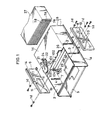
- a main chassis 1 comprises a pair of side walls 1a, 1b, and a top wall 1c, and has a lift chassis 5 disposed in its interior space.
- the main chassis 1 is formed in its top wall 1c with an opening 2 opposed to the lift chassis 5, and in its side walls 1a, 1b with vertical guide slits 3, 3 and 4.
- the lift chassis 5 has pins 6, 6 and 7 projecting from its opposite ends and serving as cam followers. These pins 6, 6 and 7 are slidably inserted through the guide slits 3, 3 and 4 in the main chassis 1, respectively for guiding the chassis 5 for upward and downward movement.
- the main chassis 1 is provided with a pair of drive slides 8, 9 along its side walls 1a, 1b.
- Each of the sldies 8 (9) has three horizontal slide slits 10, 10, 10 (11, 11, 11).
- a pipe piece 1d is inserted through each slide slit and fastened to the main chassis 1 with a screw to guide the horizontal movement of the drive slide.
- the drive slide 8 on the right side of the main chassis is formed with a pair of slanting slits 12, 12 extending downward from the opening (2) side.
- the drive slide 9 on the left side of the main chassis has a single slanting slit 13 extending downward from the opening side in a direction opposite to the slits 12. These slanting slits 12, 12 and 13 provide cam portions in engagement with the cam followers.
- the heads of the pins 6, 6, 7 projecting from the lift chassis 5 are inserted through the slanting slits 12, 12, 13, respectively.
- each of the slanting slits 12, 12, 13 is continuous with a horizontal slit portion which does not contribute to the driving of the lift chassis 5 but serves to move a tray box discharge mechanism with the movement of the drive slide 9 as will be stated later.
- a horizontally extending rack gear 14 is provided along the upper end of the left drive slide 9.
- a drive gear 15 mounted on the top wall 1c of the main chassis 1 is in mesh with the rack gear 14.
- the rack gear 14 and the drive gear 15 provide an intermittent feed mechanism as will be described later, such that the left drive slide 9 is reciprocatingly movable stepwise by drivingly rotating the drive gear 15.
- the drive slide 9 is coupled to the other drive slide 8 by a pivotal lever, and the two drive slides 8 and 9 are driven in opposite directions to each other at the same time.
- the drive gear 15 has a large gear portion 17 and a small gear portion 18.
- the large gear portion 17 is symmetrically formed with a pair of diametrically opposed slits 19 and 20.
- the top wall 1c of the main chassis 1 has mounted thereon a first transmssion gear 21 in mesh with the drive gear 15, a second transmission gear 22 meshing with the gear 21, and a motor 23 coupled to the gear 22 by a belt 24.
- the drive gear 15 is driven by the motor 23.
- the intermittent feed mechanism for driving the drive slide 9 stepwise comprises the small gear portion 18 integral with the drive gear 15, and the rack gear 14 integral with the drive slide 9.
- the small gear portion 18 has a solid cylindrical body formed with a pair of diametrically opposed gear grooves 18a and 18a in its outer periphery in a symmetric arrangement. Between the two gear grooves, the axially upper half of the outer periphery provides engaging portions 18c, 18c, and the lower half thereof has a pair of cutouts 18b, 18b over a specified angular range.
- the rack gear 14 is provided with first ridges 14a having a pitch P1, and second ridges 14b having one-half the length of the first ridges 14a and the same pitch P1 and each formed between two adjacent first ridges 14a at a distance P2, i.e. one-half of the pitch P1, therefrom.
- first ridges 14a having a pitch P1
- second ridges 14b having one-half the length of the first ridges 14a and the same pitch P1 and each formed between two adjacent first ridges 14a at a distance P2, i.e. one-half of the pitch P1, therefrom.
- the mechanism When the drive gear 15 rotates in the direction of arrow A shown in Fig. 7, the mechanism is repeatedly subjected to an operation cycle which comprises a first drive mode wherein the side wall of the small gear portion 18 defining the gear groove 18a drives the first ridge 14a of the rack gear 14, a second drive mode wherein one of the side walls arranged circumferentially of the portion 18 and defining the cutouts 18b drives the second ridge 14b of the rack gear 14, and an idle rotation mode for a change from the first drive mode to the second drive mode.
- the rack gear 14 In the first and second drive modes, the rack gear 14 is driven in the direction of arrow B.
- the second ridge 14b is accommodated in the cutout 18b, and the small gear portion 18 idly rotates for a period of time until the side wall defining the cutout 18b comes into contact with the second ridge 14b, interrupting the transmission of power to the rack gear 14.
- the engaging portion 18c of the small gear portion 18 is in intimate engagement with the rack gear 14 between two adjacent first ridges 14a, 14a to lock the rack gear 14. Consequently, with the continuous rotation of the drive gear 15, the rack gear 14 intermittently moves by one pitch P1 at a time every time the drive gear 15 rotates by one-half turn.
- the ridge pitch P1 of the rack gear 14 is determined according to the tray pitch of the tray box 27. More specifically, the pitch P1 is so determined that when the drive slide 9 moves by one pitch of the rack gear 14, the lift chassis 5 moves upward or downward by a distance equal to the tray pitch of the tray box 27.
- the first ridges 14a and the second ridges 14b of the rack gear 14 can be in a staggered arrangement and given a length about one-half of the width of the rack gear 14.
- the gear grooves 18a in the small gear portion 18 are shortened in corresponding relation to the length of the first ridges 14a.
- an optical sensor 25 opposed to an outer peripheral portion of the drive gear 15 is mounted on the top wall 1c of the main chassis 1.
- the sensor 25 comprises a light-emitting element and a photodetector arranged on the opposite sides of the outer peripheral portion of the gear 15. Every time the slits 19, 20 of the drive gear 15 pass between the light-emitting element and the photodetector, i.e., every time the gear 15 rotates by one-half turn, the sensor 25 produces one electric pulse signal for detecting the number of revolutions and the rotated position of the gear 15. As shown in Fig.
- the slits 19, 20 of the drive gear 15 are disposed on a diametrical line through the midportions of the engaging portions 18c, 18c of the small gear portion 18.
- the sensor 25 is so positioned as to detect the slit 20 when the drive gear 15 is in the rotated position shown in Fig. 7. Accordingly, the sensor 25 emits the pulse signal when the first drive mode changes to the idle mode, i.e., when the small gear portion 18 intermittently comes out of meshing engagement with the rack gear 14, whereby the completion of movement of the lift chassis 5 by a unit step is detected.
- the top wall 1c of the main chassis 1 has a raised piece 102 at the opening 2.
- a restraining lever 101 pivotally movable in a vertical plane is attached to the raised piece 102.
- a tongue 103 having a lug 106 at its lower end extends downward from the free end of the restraining lever 101.
- a spring 108 connected between the lever 101 and the main chassis 1 biases the lever 101 to rotate downward, causing the tongue 103 to extend into the main chassis 1 through the opening 2.
- the main chassis 1 is fixedly provided with a bottom plate 26, which defines an inlet 28 for the tray box 27.
- a pivotal lever 16 is pivotally movably supported at its center by a pin 16b on the rear side of the bottom plate 26.
- the pair of drive slides 8 and 9 are connected to the respective ends of the pivotal lever 16 and are thereby made movable together in directions opposite to each other as already described.
- the lift chassis 5 has a central opening 29 and an aperture 30 close to the opening 29, and is formed with a projection 104 and a recessed portion 105 at its one end closer to the tray box inlet 28.
- the projection 104 and the tongue 103 of the restraining lever 101 act to register the front ends of trays 78 accommodated in the tray box 27.
- the lift chassis 5 is in its lowered position.
- the tray box 27 is inserted into the inlet 28, the trays 78 are brought into contact with the projection 104 and the tongue 103, whereby the front ends of the trays 78 are registered with one another.
- the recessed portion 105 of the lift chassis 5 comes into contact with the lug 106 of the tongue 103, pivotally moving the restraining member 101 against the action of the spring 108.
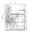
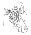
- the signal reproduction unit 31 is mounted on the top of the lift chassis 5 and comprises a spindle motor 34, a turntable 35 fixed to the output shaft of the motor 34 and a pickup 36.
- the turntable 35 and the pickup 36 are projected downward from the opening 29 of the lift chassis 5.
- the lift chassis 5 is provided with a disc loading assembly 33 for drawing the desired tray 78 from the tray box 27 and setting the disc on the tray 78 in position on the reproduction unit 31.
- the disc loading assembly 33 comprises a tray transport mechanism and a disc clamp mechanism.
- a support chassis 68 is disposed below the lift chassis 5 at a given distance from the rear side of the chassis and is fixed to the lift chassis 5 by a plurality of posts 68a.
- Cam gear means 69, a transmission gear 70 and a feed gear 71 are mounted on the upper side of the support chassis 68.
- the cam gear means 69 has a small gear 69a, a large gear 69b and a peripheral wall 72 in the form of a hollow cylinder and projecting from the lower side of the large gear 69b.
- the peripheral wall 72 is partly cut out obliquely to provide a cam portion 73.
- a projection 64a of the clamp lever 64 to be described later is in sliding contact with the peripheral wall 72 of the cam gear means 69 to regulate the angle of rotation of the clamp lever 64.
- the large gear 69b is toothed only over a specified angular range about its axis and is provided over the remaining angular range with a small-diameter hollow cylindrical portion 74 having the same diameter as the root circle of the large gear 69b and with a large-diameter hollow cylindrical portion 74a having the same diameter as the addendum circle of the gear 69b adjacent the portion 74.
- the small gear 69a of the cam gear means 69 is in mesh with a drive gear 75 for drivingly rotating the cam gear means 69.
- the rotation of the motor 58 to be described below is transmitted to the cam gear means 69 through the gear 75.
- the transmission gear 70 meshing with the large gear 69b of the cam gear means 69 has a toothless portion 76 over a specified angular range about its axis over the lower half of its thickness. As will be described later, the engagement of the large-diameter cylindrical portion 74a of the cam gear means 69 with the toothless portion 76 locks the transmission gear 70.
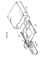
- the tray 78 for placing a disc thereon has a rack gear 79 extending along one side thereof and provided with a projection 80 at its left end.
- the tray 78 has a hooked portion 81 at its front end and a disc accommodating portion 82 formed with a central opening 83.
- the lift chassis 5 has a pair of parallel guide members 61 and 62 spaced apart by a distance corresponding to the width of the tray and each formed with a guide groove for guiding the movement of the tray.
- the tray 78 can be horizontally withdrawn from the tray box 27 through an opening 84 or placed into the box 27 while being guided by the guide members 61, 62 as seen in Fig. 10.
- a clamp lever 64 is pivotally movably supported on the rear side of the lift chassis 5 and is positioned at the midportion between the guide members 61, 62.
- the lever 64 is biased upward by a spring 100 bearing thereon and supported by the chassis 5.
- the clamp lever 64 is provided on its free end with a clamp member 63 opposed to the turntable 35.
- the clamp lever 64 has the projection 64a in sliding contact with the peripheral wall 72 of the cam gear means 69 (see Fig. 8).
- an L-shaped positioning member 65 is supported by a pivot 65a on the lift chassis 5 at the inner portion thereof toward the direction of feed of the tray so as to set the tray in position in the inner portion of the player.
- the member 65 is biased clockwise by a spring 66 and has a free end with a pin 67 projecting upward therefrom. As will be described later, the pin 67 engages with the tray 78 immediately before the completion of feed of the tray, pushing the tray toward the specified set position thereof for positioning.
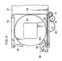
- the lift chassis 5 is provided on its upper side with a mechanism 32 for preventing the disc from slipping off. As shown in Figs. 2 and 9, this mechanism comprises a pivotal chassis 37, a cam slide 38 and a drive gear assembly 39.
- the pivotal chassis 37 is movably supported on a rod 40 supported on the lift chassis 5.
- a spring 43 is connected between a projection 41 formed at the base end of the pivotal chassis 37 and an upright pin 42 on the lift chassis 5 for biasing the pivotal chassis 37 in a direction toward the lift chassis 5.
- the pivotal chassis 37 has bifurcated ends carrying a pair of holding members 44, 45 projecting downward therefrom into the lift chassis 5 through the opening 29 and the aperture 30, respectively.
- the pivotal chassis 37 is further provided on its lower side with a projection 52 opposed to the cam slide 38.
- the cam slide 38 has a pair of slits 46, 47 extending longitudinally thereof.
- a pair of pins 48, 49 extending upright from the lift chassis 5 are inserted through the slits 46, 47, respectively, for guiding the cam slide 38 for reciprocal movement in directions along the rod 40 for the chassis 37.
- a rack gear 50 and a ridge 51 are formed on the respective longitudinal opposite sides of the cam slide 38.
- the ridge 51 comprises a low portion 51a, a high portion 51b and a slanting portion 51c interconnecting these portions.
- the projection 52 on the pivotal chassis 37 is in sliding contact with the top end face of the ridge 51 to regulate the angle of pivotal movement of the chassis 37.
- the drive gear assembly 39 comprises a pulley 53, transmission gears 54, 55 and a drive gear 56 mounted on respective shafts on the lift chassis 5.
- the drive gear 56 is in mesh with the rack gear 50 of the cam slide 38.
- the pulley 53 is coupled by a belt 60 to a pulley 59 fixed to the output shaft of a motor 58, whereby the rotation of the motor 58 is transmitted to the cam slide 38.
- the shaft 57 extending downward from the center of the pulley 53 extends through the lift chassis 5 to the rear side thereof and connected to the gear 75 of the tray transport mechanism provided on the rear side of the lift chassis 5 as already stated (see Fig. 8).
- a pivotal lever 85 carrying an operating pin 88 to be brought into contact with the tray box 27 is supported by a pivot 87 on the upper side of the main chassis bottom plate 26 and biased counterclockwise by a spring 86 connected between the lever 85 and the bottom plate 26.
- a lock lever 89 is supported by a pivot 92 on the bottom plate 26 and biased clockwise by a spring 93 connected between the bottom plate 26 and the lever 89.
- the lock lever 89 has an engaging portion 91 projecting from one free end thereof and engageable in a recessed portion 27a in the tray box 27, and a pin 90 projecting from the other free end thereof and movable by a cam face 16a on the pivotal lever 16.
- the tray box 27 When the tray box 27 is inserted into the player through the inlet 28, the front end of the tray box 27 comes into contact with the operating pin 88. As the tray box 27 is further pushed in against the spring 86, the lock lever 89 is slightly rotated counterclockwise by being pushed by the box 27. When the tray box 27 is set in position, the engaging portion 91 engages in the recessed portion 27a in the tray box 27 to lock the box 27 in its set position.
- the tray box 27 is loaded into the main chassis 1 through the inlet 28 and locked to the main chassis 1 by the lock mechanism described above.
- the operator manipulates a switch to feed an instruction signal to the system controller, specifying the disc in the lowermost position within the tray box 27 for signal reproduction.
- the motor 23 is energized, rotating the drive gear 15 by the first one-half turn and thereby raising the lift chassis 5 by one step, whereupon the motor 23 is deenergized in response to a pulse signal from the sensor 25. Consequently, the projection 80 at the front end of the lowermost tray 78 is engaged by a toothless portion 77 of an upper gear 71a on the feed gear 71 mounted on the lift chassis 5 as seen in Figs. 13 and 14.
- the motor 58 shown in Fig. 9 is energized in response to the pulse signal from the sensor 25, whereby the cam gear means 69 is initiated into clockwise rotation from the state shown in Fig. 8.
- the rotation is transmitted via the transmission gear 70 to the feed gear 71, which in turn is driven clockwise.
- the projection 64a of the clamp lever 64 is disengaged from the cam portion 73 of the cam gear means 69, whereby the clamp lever 64 is retained as pivotally moved in a direction opposite to the biasing direction.
- the clamp member 63 is at a sufficient distance away from the turntable 35.
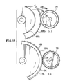
- the toothless portion 76 of the transmission gear 70 comes into engagement with the large-diameter cylindrical portion 74a of the cam gear means 69, with the toothed portion of the gear 70 above the toothless portion 76 thereof facing the small-diameter cylindrical portion 74 of the cam gear means 69 as shown in Figs. 15 (a) and (b). Consequently, transmission gear 70 no longer rotates despite further rotation of the cam gear means 69 but is locked by the engagement of the toothless portion 76 with the cylindrical portion 74a as seen in Figs. 16 (a) and (b). Thus, the tray 78 is completely fed by the feed gear 71.
- a bevel face 81a of the hooked portion 81 of the tray 78 shown in Fig. 11 comes into contact with the pin 67 on the positioning member 65. Further travel of the tray 78 to the terminal end rotates the positioning member 65 against the spring 66, eventually causing the pin 67 to pass over the bevel face 81a and fit in an engaging portion 81b of the hooked portion 81. During the engagement of the pin 67 in the engaging portion 81b, the tray 78 is further pushed in by the force of the spring 66, precluding the feed gear 71 from backlashing relative to the rack gear 79. As a result, the tray 78 is positioned in place, whereby the tray feeding operation is completed.
- the projection 64a of the clamp lever 64 shown in Fig. 12 reaches the cam portion 73 of the cam gear means 69.
- the clamp lever 64 is pivotally moved upward by the action of the spring 100, thereby raising the clamp member 63.
- the clamp member 63 is projected upward through the central opening 83 of the tray 78 which is positioned above the clamp member 63, whereby the disc on the tray 78 is raised off the tray by the clamp member 63 and pressed against the turntable 35.
- the disc is prevented from slipping off by the mechanism 32 as described below.
- the cam slide 38 In the initial state shown in Fig. 2 before the tray feed operation, the cam slide 38 is in the terminal position of its movement in the direction of arrow D. At this time, the projection on the pivotal chassis 37 is in sliding contact with the low portion 51a of the ridge 51 of the cam slide 38 shown in Fig. 9, with the holding members 44, 45 projecting downward beyond the lift chassis 5 through the opening 29 and the aperture 30.
- the rotation of the motor 58 is delivered via the pulley 53 and the transmission gears 54, 55 to the drive gear 56, which in turn drives the cam slide 38 in the direction of arrow D ⁇ .
- the projection 52 of the pivotal chassis 5 slides along the low portion 51a of the cam slide 38, with the holding members 44, 45 held projected downward beyond the lift chassis 5 until the projection 52 reaches the slanting portion 51c of the ridge 51.
- the projection 52 reaches the slanting portion 51c when the tray 78 is completely brought to the fed position.
- the holding members 44, 45 held projected beyond the lower surface of the lift chassis 5 are thereby maintained slightly above the disc on the tray 78 to prevent the disc from slipping off the tray 78 as by impact.
- the reproduction unit 31 operates for the reproduction of signals.
- the disc After the disc has been played for reproduction, the disc is returned to the tray box 27 by a procedure reverse to the above.
- the sixth disc from the lowermost position is selected by the following operation.
- the motor 23 is driven to rotate the drive gear 15 and thereby raise the lift chassis 5 stepwise.
- the number of pulse signals from the sensor 25 is counted by the system controller, and when five pulses have been counted up, the motor 23 is deenergized. Consequently, the lift chassis 5 is raised by five steps and positioned at the level for the sixth tray.
- the toothless portion 77 of the feed gear 71 on the lift chassis 5 repeatedly engages with and disengages from the projections 80 at the front ends of the trays 78 with the rise of the lift chassis 5.
- the feed gear 71 will not be caught by the tray 78, permitting the lift chassis 5 to move smoothly.
- the tray is fed, the disc is clamped and prevented from slipping off, and the reproduction unit 31 operates for signal reproduction in the same manner as already described.
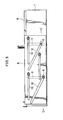
- the lift chassis 5 When no instruction is given for reproducing the signals from another disc after one disc has been played, the lift chassis 5 is lowered to the lowermost position, and the tray box 27 can be then discharged. More specifically, from the state shown in Fig. 5, the drive slide 8 is driven in the direction of arrow C, and the drive slide 9 in the direction of arrow C ⁇ , whereby the pins 6, 6, 7 through the drive slides 8, 9 are fitted into the horizontal portions continuous with the slanting slits 12, 12, 13 without moving the lift chassis 5.
- the slanting slits 12, 12, 13 in the drive slides 8, 9 are straight, so that the pins 6, 7 on the lift chassis 5 can be driven without any marked change in the load to move the lift chassis 5 stepwise smoothly.
- the slanting slits 12, 12, 13 are each formed at one end with the horizontal portion for discharging the tray.
- the drive slides 8, 9 can therefore be of a shorter length than the conventional drive slides formed with steplike slanting slits, consequently shortening the dimension of the disc player in the direction along the slides.
- the engaging portion 18b of the small gear portion 18 of the drive gear 15 comes into intimate contact with the rack gear 14 between the first ridges 14a, 14a to lock the rack gear 14, thereby preventing the movement of the drive slides 8, 9. Consequently, the lift chassis 5 can be held properly at the specified level.
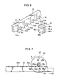
- the drive mechanism for discharging the tray box 27 may comprise a pivotal arm 94 operatively associated with the drive slide 8 as seen in Figs. 17 to 20.
- the pivotal arm 94 is supported by a pivot 97 on the bottom plate of the main chassis 1, and the drive slide 8 is provided with a projection 8a at its one end.
- the pivotal arm 94 has at its opposite ends pins 95 and 96 opposed to the projection 8a and the tray box 27, respectively.
- the projection 8a pushes the pin 95 to move the arm 94 counterclockwise. With this movement, the pin 96 on the arm 94 pushes the tray box 27 toward the discharging direction.
- the tray box 27 can be discharged with good stability by this arrangement regardless of the number of discs accommodated in the tray box 27, i.e., of the weight of the box 27.
- the lock lever 89 can be adapted to disengage from the tray box 27 by a pin 98 mounted on the lock lever 89 and in engagement with the projection 8a on the drive slide 8.
- the drive slide 8 when moved, moves the lock lever 89 counterclockwise, disengaging the engaging portion 91 from the recessed portion 27a of the tray box 27.
- Figs. 17 and 18 has the drawback that since the drive slide 8 is moved stepwise, the tray box 27 is discharged by an intermittent movement. It is desirable that the drive slide be driven continuously during the discharge of the tray box 27.
- Fig. 6B shows gear means constructed from such viewpoint.
- the small gear portion 18 has an auxiliary ridge 18d at an intermediate position in the cutout 18b.
- the rack gear 14 is formed with third ridges 14c along with first ridges 14a at the gear terminal end portion (section Q shown).
- the auxiliary ridge 18d has such a length as to engage only with the third ridge 14c.
- the auxiliary ridge 18d of the small gear portion 18 is held out of engagement with the second ridge 14b, so that the portion 18 idly rotates between two adjacent first ridges 14a, 14a, whereby the rack gear 14 can be advanced stepwise in the same manner as already stated.
- the auxiliary ridge 18d engages with the third ridge 14c on the rack gear 14 without permitting the idle rotation of the gear portion 18 to continuously drive the rack gear 14.
- the tray box 27 can be discharged through a continuous movement when the section Q is provided at the portion of the drive slide 8 which contributes to the discharge of the tray box.
Landscapes
- Feeding And Guiding Record Carriers (AREA)
- Automatic Disk Changers (AREA)
Applications Claiming Priority (4)
| Application Number | Priority Date | Filing Date | Title |
|---|---|---|---|
| JP4950687A JPH0636271B2 (ja) | 1987-03-04 | 1987-03-04 | デイスクプレ−ヤのオ−トチエンジヤ− |
| JP49506/87 | 1987-03-04 | ||
| JP165605/87 | 1987-10-29 | ||
| JP1987165605U JPH0636526Y2 (ja) | 1987-10-29 | 1987-10-29 | デイスクプレーヤ |
Publications (3)
| Publication Number | Publication Date |
|---|---|
| EP0284815A2 true EP0284815A2 (de) | 1988-10-05 |
| EP0284815A3 EP0284815A3 (en) | 1989-12-06 |
| EP0284815B1 EP0284815B1 (de) | 1993-11-03 |
Family
ID=26389903
Family Applications (1)
| Application Number | Title | Priority Date | Filing Date |
|---|---|---|---|
| EP88103301A Expired - Lifetime EP0284815B1 (de) | 1987-03-04 | 1988-03-03 | Plattenspieler |
Country Status (6)
| Country | Link |
|---|---|
| US (1) | US4796244A (de) |
| EP (1) | EP0284815B1 (de) |
| KR (1) | KR910003937B1 (de) |
| CN (1) | CN1013529B (de) |
| CA (1) | CA1307587C (de) |
| DE (1) | DE3885326T2 (de) |
Cited By (12)
| Publication number | Priority date | Publication date | Assignee | Title |
|---|---|---|---|---|
| EP0492764A1 (de) * | 1990-12-19 | 1992-07-01 | Pioneer Electronic Corporation | Plattenspieler mit Magazin |
| EP0493034A1 (de) * | 1990-12-22 | 1992-07-01 | Sony Corporation | Plattenspieler |
| EP0500396A2 (de) * | 1991-02-22 | 1992-08-26 | Sony Corporation | Bandkassette |
| EP0506458A2 (de) * | 1991-03-29 | 1992-09-30 | Sony Corporation | Automatisches Plattenwechsel-Wiedergabegerät |
| EP0581518A2 (de) * | 1992-07-27 | 1994-02-02 | Sony Corporation | Plattenwechsler für Plattenspieler |
| EP0594118A2 (de) * | 1992-10-19 | 1994-04-27 | CLARION Co., Ltd. | Aufzeichnungs- und Wiedergabegerät |
| EP0614183A2 (de) * | 1993-03-05 | 1994-09-07 | Nakamichi Corporation | Magazinplattenspieler mit umschaltbarer Antriebsvorrichtung |
| EP0712126A3 (de) * | 1994-11-12 | 1997-01-22 | Sanyo Electric Co | Mehrplattenspieler |
| EP0813195A2 (de) * | 1996-06-10 | 1997-12-17 | Eastman Kodak Company | Gerät zum Entnehmen eines Plattenträgers aus und/oder dessen Wiedereinführen in ein Wechselmagazin |
| EP0817184A2 (de) * | 1996-07-04 | 1998-01-07 | Pioneer Electronic Corporation | Automstischer Plattenwechsler mit Plattenspieler-Trägervorrichtung |
| EP0871168A2 (de) * | 1997-04-08 | 1998-10-14 | Sony Corporation | Plattenaufzeichnungs/Wiedergabegerät und darin verwendeter Plattenbehälter |
| CN1042371C (zh) * | 1993-12-14 | 1999-03-03 | 阿尔派株式会社 | 选择式盘重放装置 |
Families Citing this family (22)
| Publication number | Priority date | Publication date | Assignee | Title |
|---|---|---|---|---|
| JPH0510280Y2 (de) * | 1987-07-03 | 1993-03-12 | ||
| DE3728587A1 (de) * | 1987-08-27 | 1989-03-09 | Thomson Brandt Gmbh | Vorrichtung zur entnahme und zum abspielen eines plattenfoermigen aufzeichnungstraegers aus den faechern eines magazins |
| JPH0197447U (de) * | 1987-12-21 | 1989-06-28 | ||
| NL8800859A (nl) * | 1988-04-05 | 1989-11-01 | Philips Nv | Platenwisselaar, alsmede platenspeler voorzien van de platenwisselaar. |
| US5191569A (en) * | 1989-05-15 | 1993-03-02 | Pioneer Electronic Corporation | Disk playback device |
| GB2241104A (en) * | 1990-02-16 | 1991-08-21 | Pioneer Electronic Corp | Stopper for trays in a magazine of a cd player |
| JP3076587B2 (ja) * | 1990-05-31 | 2000-08-14 | ナカミチ株式会社 | チェンジャー型ディスク再生装置 |
| US5241529A (en) * | 1990-05-31 | 1993-08-31 | Nakamichi Corporation | Disk player with disk-carrier lock-up device |
| US5239527A (en) * | 1990-05-31 | 1993-08-24 | Nakamichi Corporation | Disc changer for inserting, ejecting and playing discs |
| JP2616512B2 (ja) * | 1991-06-06 | 1997-06-04 | 松下電器産業株式会社 | ディスクチェンジャー装置 |
| DE4317546A1 (de) * | 1992-05-27 | 1994-01-20 | Funai Electric Co | Plattenspieler mit automatischem Plattenwechsler |
| JPH06259864A (ja) * | 1993-03-05 | 1994-09-16 | Nakamichi Corp | ディスク再生装置 |
| EP0614178A3 (de) * | 1993-03-05 | 1994-10-12 | Nakamichi Corp | Plattenspieler mit Compact-Disktransportvorrichtung. |
| JP3183744B2 (ja) * | 1993-03-05 | 2001-07-09 | ナカミチ株式会社 | チェンジャ機能を備えたディスク再生装置 |
| US5508994A (en) * | 1993-03-05 | 1996-04-16 | Nakamichi Corporation | Disk player with compact arrangement of a reader and disk storage magazine |
| JPH06259869A (ja) * | 1993-03-05 | 1994-09-16 | Nakamichi Corp | ディスク再生装置 |
| JP2596255Y2 (ja) * | 1993-03-23 | 1999-06-07 | ナカミチ株式会社 | ディスク再生装置 |
| JPH06349186A (ja) * | 1993-06-03 | 1994-12-22 | Nakamichi Corp | ディスク再生装置 |
| US5802021A (en) * | 1994-04-14 | 1998-09-01 | Sony Corporation | Disc recording and/or reproducing apparatus and disc recording media exchange apparatus |
| JPH09231738A (ja) * | 1996-02-28 | 1997-09-05 | Sony Corp | スライドトレーにおける接地構造 |
| DE69815036T2 (de) * | 1997-03-10 | 2004-04-08 | Mitsubishi Denki K.K. | Plattenvorrichtung |
| US8250993B2 (en) * | 2009-12-18 | 2012-08-28 | Krueger International, Inc. | Laptop computer storage assembly for a work surface |
Citations (5)
| Publication number | Priority date | Publication date | Assignee | Title |
|---|---|---|---|---|
| US4561085A (en) * | 1983-09-30 | 1985-12-24 | Pioneer Electronic Corporation | Front loading disc player |
| US4574372A (en) * | 1983-01-18 | 1986-03-04 | Staar S.A. | Locking device for record player apparatus |
| US4587585A (en) * | 1982-12-21 | 1986-05-06 | Alps Electric Co., Ltd. | Loading/ejecting device for a magnetic disk cartridge |
| FR2578676A1 (fr) * | 1985-03-08 | 1986-09-12 | Pioneer Electronic Corp | Appareil a plusieurs disques d'audiofrequences et a lecteur incorpores |
| JPS62239375A (ja) * | 1986-04-08 | 1987-10-20 | Mitsubishi Electric Corp | 情報処理装置 |
Family Cites Families (3)
| Publication number | Priority date | Publication date | Assignee | Title |
|---|---|---|---|---|
| US4561078A (en) * | 1982-08-11 | 1985-12-24 | U.S. Philips Corporation | Disc changer and disc holder and box for use with such a changer |
| JPS6065279U (ja) * | 1983-10-08 | 1985-05-09 | 日本マランツ株式会社 | コンパクトデイスクプレ−ヤのトレイボツクス |
| EP0168107A3 (de) * | 1984-07-11 | 1988-01-13 | Koninklijke Philips Electronics N.V. | Magazin für eine Vielzahl von in Behältern aufgenommenen plattenförmigen Informationsträgern und Kombination eines Plattenspielers mit solch einem Magazin |
-
1988
- 1988-03-02 KR KR1019880002210A patent/KR910003937B1/ko not_active IP Right Cessation
- 1988-03-02 CA CA000560355A patent/CA1307587C/en not_active Expired - Lifetime
- 1988-03-03 EP EP88103301A patent/EP0284815B1/de not_active Expired - Lifetime
- 1988-03-03 DE DE88103301T patent/DE3885326T2/de not_active Expired - Lifetime
- 1988-03-03 US US07/163,913 patent/US4796244A/en not_active Expired - Lifetime
- 1988-03-04 CN CN88101181A patent/CN1013529B/zh not_active Expired
Patent Citations (5)
| Publication number | Priority date | Publication date | Assignee | Title |
|---|---|---|---|---|
| US4587585A (en) * | 1982-12-21 | 1986-05-06 | Alps Electric Co., Ltd. | Loading/ejecting device for a magnetic disk cartridge |
| US4574372A (en) * | 1983-01-18 | 1986-03-04 | Staar S.A. | Locking device for record player apparatus |
| US4561085A (en) * | 1983-09-30 | 1985-12-24 | Pioneer Electronic Corporation | Front loading disc player |
| FR2578676A1 (fr) * | 1985-03-08 | 1986-09-12 | Pioneer Electronic Corp | Appareil a plusieurs disques d'audiofrequences et a lecteur incorpores |
| JPS62239375A (ja) * | 1986-04-08 | 1987-10-20 | Mitsubishi Electric Corp | 情報処理装置 |
Cited By (29)
| Publication number | Priority date | Publication date | Assignee | Title |
|---|---|---|---|---|
| US5226025A (en) * | 1990-12-19 | 1993-07-06 | Pioneer Electronic Corporation | Magazine disk player having an improved magazine detecting feature |
| EP0492764A1 (de) * | 1990-12-19 | 1992-07-01 | Pioneer Electronic Corporation | Plattenspieler mit Magazin |
| EP0493034A1 (de) * | 1990-12-22 | 1992-07-01 | Sony Corporation | Plattenspieler |
| US5956300A (en) * | 1990-12-22 | 1999-09-21 | Sony Corporation | Compact audio disc changer with disc drive mounted on movable elevator |
| EP0500396A2 (de) * | 1991-02-22 | 1992-08-26 | Sony Corporation | Bandkassette |
| EP0500396A3 (en) * | 1991-02-22 | 1993-07-14 | Sony Corporation | Tape cassette |
| EP0506458A3 (de) * | 1991-03-29 | 1995-03-01 | Sony Corp | |
| EP0506458A2 (de) * | 1991-03-29 | 1992-09-30 | Sony Corporation | Automatisches Plattenwechsel-Wiedergabegerät |
| EP0581518A2 (de) * | 1992-07-27 | 1994-02-02 | Sony Corporation | Plattenwechsler für Plattenspieler |
| EP0813196A2 (de) * | 1992-07-27 | 1997-12-17 | Sony Corporation | Plattenwechsler für Plattenspieler |
| EP0581518A3 (de) * | 1992-07-27 | 1994-11-30 | Sony Corp | Plattenwechsler für Plattenspieler. |
| EP0813196A3 (de) * | 1992-07-27 | 1997-12-29 | Sony Corporation | Plattenwechsler für Plattenspieler |
| US5481513A (en) * | 1992-07-27 | 1996-01-02 | Sony Corporation | Disc changing apparatus for disc player including improved translating chassis and eject mechanism for disc magazine |
| EP0594118A3 (en) * | 1992-10-19 | 1996-08-28 | Clarion Co Ltd | Recording and playback unit |
| EP0779620A3 (de) * | 1992-10-19 | 1998-05-20 | CLARION Co., Ltd. | Plattengerät |
| EP0594118A2 (de) * | 1992-10-19 | 1994-04-27 | CLARION Co., Ltd. | Aufzeichnungs- und Wiedergabegerät |
| EP0614183A3 (de) * | 1993-03-05 | 1994-11-23 | Nakamichi Corp | Magazinplattenspieler mit umschaltbarer Antriebsvorrichtung. |
| EP0614183A2 (de) * | 1993-03-05 | 1994-09-07 | Nakamichi Corporation | Magazinplattenspieler mit umschaltbarer Antriebsvorrichtung |
| US5528442A (en) * | 1993-03-05 | 1996-06-18 | Nakamichi Corporation | Disk player with magazine switched drive source |
| CN1042371C (zh) * | 1993-12-14 | 1999-03-03 | 阿尔派株式会社 | 选择式盘重放装置 |
| EP0712126A3 (de) * | 1994-11-12 | 1997-01-22 | Sanyo Electric Co | Mehrplattenspieler |
| EP0813195A3 (de) * | 1996-06-10 | 1998-01-14 | Eastman Kodak Company | Gerät zum Entnehmen eines Plattenträgers aus und/oder dessen Wiedereinführen in ein Wechselmagazin |
| US5847901A (en) * | 1996-06-10 | 1998-12-08 | Eastman Kodak Company | Apparatus for removing a plate holder from and/or returning it to an exchangeable magazine |
| EP0813195A2 (de) * | 1996-06-10 | 1997-12-17 | Eastman Kodak Company | Gerät zum Entnehmen eines Plattenträgers aus und/oder dessen Wiedereinführen in ein Wechselmagazin |
| EP0817184A3 (de) * | 1996-07-04 | 1998-01-28 | Pioneer Electronic Corporation | Automstischer Plattenwechsler mit Plattenspieler-Trägervorrichtung |
| EP0817184A2 (de) * | 1996-07-04 | 1998-01-07 | Pioneer Electronic Corporation | Automstischer Plattenwechsler mit Plattenspieler-Trägervorrichtung |
| EP0871168A2 (de) * | 1997-04-08 | 1998-10-14 | Sony Corporation | Plattenaufzeichnungs/Wiedergabegerät und darin verwendeter Plattenbehälter |
| EP0871168A3 (de) * | 1997-04-08 | 1998-12-23 | Sony Corporation | Plattenaufzeichnungs-/-wiedergabegerät und darin verwendeter Plattenbehälter |
| US6307828B1 (en) | 1997-04-08 | 2001-10-23 | Sony Corporation | Disc recording/reproducing apparatus and disc container casing used therein |
Also Published As
| Publication number | Publication date |
|---|---|
| DE3885326T2 (de) | 1994-03-03 |
| EP0284815A3 (en) | 1989-12-06 |
| CN88101181A (zh) | 1988-09-14 |
| CN1013529B (zh) | 1991-08-14 |
| KR880011771A (ko) | 1988-10-31 |
| EP0284815B1 (de) | 1993-11-03 |
| KR910003937B1 (ko) | 1991-06-17 |
| CA1307587C (en) | 1992-09-15 |
| DE3885326D1 (de) | 1993-12-09 |
| US4796244A (en) | 1989-01-03 |
Similar Documents
| Publication | Publication Date | Title |
|---|---|---|
| US4796244A (en) | Disc player | |
| KR0147065B1 (ko) | 디스크 플레이어 | |
| US5247500A (en) | Elevating and lowering system in a multi-disk player | |
| US5140579A (en) | Disk loading device for disk player | |
| US5963533A (en) | Disk playback device with changer allowing playback of one disk while another can be exchanged | |
| EP1610319B1 (de) | Plattengerät | |
| EP1482496A1 (de) | Platten-Abspielgerät mit Plattenwechsler | |
| US6198713B1 (en) | Power transmitting mechanism for disk apparatus | |
| JP2721800B2 (ja) | ディスクチェンジャー | |
| JP2698257B2 (ja) | ディスクのローディング装置 | |
| US4477889A (en) | Recording media selecting mechanism | |
| KR940005010Y1 (ko) | 멀티 콤팩트 디스크 플레이어의 매거진 및 트레이 로딩장치 | |
| JPS63217561A (ja) | ディスクプレ−ヤ | |
| JP2731111B2 (ja) | クランパー支持構造 | |
| JP2679072B2 (ja) | マルチディスクプレーヤ | |
| KR100186264B1 (ko) | 디스크의 로딩 장치 | |
| JPH0752549B2 (ja) | デイスクプレ−ヤのオ−トチエンジヤ− | |
| JPH0636270B2 (ja) | デイスクプレ−ヤのオ−トチエンジヤ− | |
| JPH01151058A (ja) | マルチディスクプレヤー | |
| JPH0320826B2 (de) | ||
| KR960014397B1 (ko) | 멀티디스크 플레이어의 로딩, 언로딩장치 | |
| JP3933858B2 (ja) | ディスク選択式ディスク装置 | |
| JPS63217564A (ja) | デイスクプレ−ヤのオ−トチエンジヤ− | |
| JP3108980B2 (ja) | ディスク演奏装置 | |
| JP2531641Y2 (ja) | マルチディスクプレーヤのディスク取出し位置記憶装置 |
Legal Events
| Date | Code | Title | Description |
|---|---|---|---|
| PUAI | Public reference made under article 153(3) epc to a published international application that has entered the european phase |
Free format text: ORIGINAL CODE: 0009012 |
|
| AK | Designated contracting states |
Kind code of ref document: A2 Designated state(s): DE FR GB IT |
|
| PUAL | Search report despatched |
Free format text: ORIGINAL CODE: 0009013 |
|
| AK | Designated contracting states |
Kind code of ref document: A3 Designated state(s): DE FR GB IT |
|
| 17P | Request for examination filed |
Effective date: 19900525 |
|
| 17Q | First examination report despatched |
Effective date: 19920224 |
|
| GRAA | (expected) grant |
Free format text: ORIGINAL CODE: 0009210 |
|
| AK | Designated contracting states |
Kind code of ref document: B1 Designated state(s): DE FR GB IT |
|
| PG25 | Lapsed in a contracting state [announced via postgrant information from national office to epo] |
Ref country code: IT Free format text: LAPSE BECAUSE OF FAILURE TO SUBMIT A TRANSLATION OF THE DESCRIPTION OR TO PAY THE FEE WITHIN THE PRESCRIBED TIME-LIMIT;WARNING: LAPSES OF ITALIAN PATENTS WITH EFFECTIVE DATE BEFORE 2007 MAY HAVE OCCURRED AT ANY TIME BEFORE 2007. THE CORRECT EFFECTIVE DATE MAY BE DIFFERENT FROM THE ONE RECORDED. Effective date: 19931103 |
|
| REF | Corresponds to: |
Ref document number: 3885326 Country of ref document: DE Date of ref document: 19931209 |
|
| ET | Fr: translation filed | ||
| PLBE | No opposition filed within time limit |
Free format text: ORIGINAL CODE: 0009261 |
|
| STAA | Information on the status of an ep patent application or granted ep patent |
Free format text: STATUS: NO OPPOSITION FILED WITHIN TIME LIMIT |
|
| 26N | No opposition filed | ||
| REG | Reference to a national code |
Ref country code: GB Ref legal event code: IF02 |
|
| PGFP | Annual fee paid to national office [announced via postgrant information from national office to epo] |
Ref country code: GB Payment date: 20070228 Year of fee payment: 20 |
|
| PGFP | Annual fee paid to national office [announced via postgrant information from national office to epo] |
Ref country code: DE Payment date: 20070301 Year of fee payment: 20 |
|
| REG | Reference to a national code |
Ref country code: GB Ref legal event code: PE20 |
|
| PGFP | Annual fee paid to national office [announced via postgrant information from national office to epo] |
Ref country code: FR Payment date: 20070308 Year of fee payment: 20 |
|
| PG25 | Lapsed in a contracting state [announced via postgrant information from national office to epo] |
Ref country code: GB Free format text: LAPSE BECAUSE OF EXPIRATION OF PROTECTION Effective date: 20080302 |