EP0281759B1 - Einrichtung zur Halterung der Entmagnetisierungsspule an der Bildröhre - Google Patents
Einrichtung zur Halterung der Entmagnetisierungsspule an der Bildröhre Download PDFInfo
- Publication number
- EP0281759B1 EP0281759B1 EP88101509A EP88101509A EP0281759B1 EP 0281759 B1 EP0281759 B1 EP 0281759B1 EP 88101509 A EP88101509 A EP 88101509A EP 88101509 A EP88101509 A EP 88101509A EP 0281759 B1 EP0281759 B1 EP 0281759B1
- Authority
- EP
- European Patent Office
- Prior art keywords
- bracket
- picture tube
- coil
- centre
- mounting
- Prior art date
- Legal status (The legal status is an assumption and is not a legal conclusion. Google has not performed a legal analysis and makes no representation as to the accuracy of the status listed.)
- Expired - Lifetime
Links
- 230000005347 demagnetization Effects 0.000 title description 6
- 239000002184 metal Substances 0.000 claims description 8
- 229910052751 metal Inorganic materials 0.000 claims description 8
- OKTJSMMVPCPJKN-UHFFFAOYSA-N Carbon Chemical compound [C] OKTJSMMVPCPJKN-UHFFFAOYSA-N 0.000 claims description 4
- 239000004952 Polyamide Substances 0.000 claims description 2
- 239000011248 coating agent Substances 0.000 claims description 2
- 238000000576 coating method Methods 0.000 claims description 2
- 239000011521 glass Substances 0.000 claims description 2
- 229920002647 polyamide Polymers 0.000 claims description 2
- 239000004033 plastic Substances 0.000 description 4
- 230000002093 peripheral effect Effects 0.000 description 2
- RYGMFSIKBFXOCR-UHFFFAOYSA-N Copper Chemical compound [Cu] RYGMFSIKBFXOCR-UHFFFAOYSA-N 0.000 description 1
- 230000032683 aging Effects 0.000 description 1
- 229910052802 copper Inorganic materials 0.000 description 1
- 239000010949 copper Substances 0.000 description 1
- 230000001419 dependent effect Effects 0.000 description 1
- 238000011161 development Methods 0.000 description 1
- 230000018109 developmental process Effects 0.000 description 1
- 210000005069 ears Anatomy 0.000 description 1
- 230000000694 effects Effects 0.000 description 1
- 239000003365 glass fiber Substances 0.000 description 1
- 230000001771 impaired effect Effects 0.000 description 1
- 238000002347 injection Methods 0.000 description 1
- 239000007924 injection Substances 0.000 description 1
- 230000005389 magnetism Effects 0.000 description 1
- 230000003068 static effect Effects 0.000 description 1
- 230000035882 stress Effects 0.000 description 1
Images
Classifications
-
- H—ELECTRICITY
- H04—ELECTRIC COMMUNICATION TECHNIQUE
- H04N—PICTORIAL COMMUNICATION, e.g. TELEVISION
- H04N9/00—Details of colour television systems
- H04N9/12—Picture reproducers
- H04N9/16—Picture reproducers using cathode ray tubes
- H04N9/29—Picture reproducers using cathode ray tubes using demagnetisation or compensation of external magnetic fields
-
- H—ELECTRICITY
- H01—ELECTRIC ELEMENTS
- H01J—ELECTRIC DISCHARGE TUBES OR DISCHARGE LAMPS
- H01J29/00—Details of cathode-ray tubes or of electron-beam tubes of the types covered by group H01J31/00
- H01J29/003—Arrangements for eliminating unwanted electromagnetic effects, e.g. demagnetisation arrangements, shielding coils
-
- H—ELECTRICITY
- H01—ELECTRIC ELEMENTS
- H01J—ELECTRIC DISCHARGE TUBES OR DISCHARGE LAMPS
- H01J2229/00—Details of cathode ray tubes or electron beam tubes
- H01J2229/0007—Elimination of unwanted or stray electromagnetic effects
- H01J2229/0046—Preventing or cancelling fields within the enclosure
- H01J2229/0053—Demagnetisation
Definitions
- a demagnetizing coil is required on the picture tube in a color television receiver. This is fed with a decaying alternating current each time the receiver is switched on and brings about demagnetization of the shadow mask, since otherwise magnetism of the shadow mask due to earth fields and the like can cause color purity errors.
- the demagnetizing coil consists, for example, of two saddle-shaped coils or also a continuously wound coil which is placed around the cone of the picture tube in the front area. The coil must therefore be held on the relatively bulky glass tube of the picture tube, which has few fastening options. This bracket requires several parts such as Clips, plastic straps, springs and the like. The manual attachment of the coil or coils to the picture tube therefore takes a relatively long time. It has also been shown that the demagnetization coil is not always in the optimal position relative to the picture tube due to improper attachment or signs of aging of the fastening, so that the demagnetization does not work optimally and color purity errors remain.
- the invention has for its object to provide a device for holding the demagnetizing coil on the picture tube, which is structurally simple, requires few components and allows quick and easy manual attachment of the coil to the picture tube.
- the device according to the invention has several advantages. While known devices for holding the coil required a larger number of about ten individual parts, only the brackets need to be snapped into the edge of the bilotube at both ends of the invention. Then the coil is hung in brackets on the bracket. The spring action of the deflected brackets then causes the coils to be held tightly on the cone part of the picture tube. Additional individual parts for fastening the bracket to the picture tube or the coil to the bracket are not necessary. This results in a particularly simple and quick assembly of the coil on the picture tube. The optimal position of the coil for demagnetization relative to the picture tube is maintained practically without major deviations. This always results in optimal demagnetization with low copper expenditure for the coil.
- the bracket can also be used to hold the so-called ground strap, which causes the Aquadag coating of the picture tube to be grounded. Preferably two brackets are provided for holding two coils between the brackets.
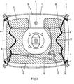
- FIG. 1 shows the picture tube 1 with the four flanges or ears 2 for attachment to the front panel of the television receiver, the Aquadag covering 3, the peripheral edge 4 of the metal frame surrounding the picture tube 1 and the high-voltage connection 5.
- a plastic bracket 6 is provided on both vertical sides of the picture tube 1 .
- the bracket 6 is placed with its two ends by a positive locking connection 7 on the peripheral edge 4 of the metal frame.
- the bracket 6 has at its two ends a receptacle 9 and outside two receptacles 8, in each of which a demagnetizing coil 10 is inserted.
- the receptacles 8, 9 are rounded on the support of the coil 10 and adapted to the course and shape or coil 10 so that the coil 10 is not kinked, pressed in or otherwise impaired by the brackets 8, 9.
- the bracket 6 is resilient in its central region 11 by a wave-shaped configuration, sc that the two coils 10 are held tightly in a defined position on the picture tube 1 by the spring action of the bracket 6.
- the bracket 6 is formed symmetrically on both sides of its center 11.
- the two brackets 6 thus form a total of eight mounting points for the two coils 10.
- the brackets 6 on both vertical sides of the picture tube 1 also serve to hold the ground strap 12, which rests on the Aquadag covering 3 and is used to ground this covering.
- the ground strap 12 is preferably designed as a conductive rubber strap according to the earlier application EP-A 0 248 367.
- the two demagnetizing coils 10 are connected via the plug 13 to the alternating voltage source of the receiver circuit which supplies the demagnetizing current.
- the two brackets 6 consist of a plastic, e.g. made of a glass fiber reinforced polyamide.
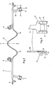
- FIG. 2 shows a top view of the structural design of the bracket 6.
- the two brackets 9 at the two ends of the bracket 6 are shaped as a fork-shaped, rounded design, against which the coil 10 bears without any significant buckling or other stress.
- the brackets 8 have an approximately part-circular course and form soft deflection points for the coils 10.
- the latching means 7 are designed in the form of a fork-shaped clamp and can be snapped onto the edge 4 of the metal frame in a corresponding manner in corresponding recesses.
- the bracket 6 In the area of its center 11, the bracket 6 has a sinusoidal shape with a sine half-wave 14 directed towards the picture tube axis and towards the coil 10, on the two sides of which two further sine half-waves 15, 16 lie in the opposite direction.
- This sinusoidal shape of the bracket 6 achieves the following:
- the latching means 7 at the two ends of the bracket 6 form, to a certain extent, fixed points after the bracket 6 is attached to the edge 4. That way te the bracket 6 can no longer be resilient because a length compensation is necessary for a spring effect.
- This length compensation is achieved by the sine half-waves 14-16.
- the bracket 6 is stressed, that is to say the deflection in the direction of the picture tube axis by the coils 10, the three sine half-waves 14, 15, 16 shown are advantageously stretched uniformly, that is to say they are used uniformly to achieve the spring action.
- the angle at the sinus domes ie the angle that the straight lines form there with the slope of the zero crossings, is increased from approximately 75 ° to 80 ° to 110 ° . It is particularly important and advantageous that the sine half-wave 14 is directed in the middle in the direction of the resilient loading, that is to say in the direction of the picture tube axis. This configuration also achieves an optimal connection of the resilient part 14-16 to the adjoining, essentially rigid part of the bracket 6 between the brackets 8, 9.
- Figure 3 shows the design of the locking connections 7.
- a fork-shaped clamping device 17 is connected via an arm 18.
- the clamping device 17 contains an essentially rigid web 19 which engages with a barb 20 in a form-fitting manner in a recess in the edge 4.
- the ground strap 12 is clamped between the web 19 and the resilient ribs 21 arranged on both sides and is thereby pressed against the edge 4 of the metal frame. Since the metal frame surrounding the picture tube 1 is grounded with the edge 4 via the conductive ground strap 12 connected to the device ground, which is necessary to avoid static charges.
- All parts shown in Figure 2, 3 consist of a plastic injection molded part.
Landscapes
- Physics & Mathematics (AREA)
- Electromagnetism (AREA)
- Engineering & Computer Science (AREA)
- Multimedia (AREA)
- Signal Processing (AREA)
- Video Image Reproduction Devices For Color Tv Systems (AREA)
- Clamps And Clips (AREA)
- Image-Pickup Tubes, Image-Amplification Tubes, And Storage Tubes (AREA)
- Transforming Light Signals Into Electric Signals (AREA)
- Vessels, Lead-In Wires, Accessory Apparatuses For Cathode-Ray Tubes (AREA)
- Studio Devices (AREA)
Description
- In einem Farbfernsehempfänger ist an der Bildröhre eine Entmagnetisierungsspule erforderlich. Diese wird jeweils beim Einschalten des Empfängers mit einem abklingenden Wechselstrom gespeist und bewirkt eine Entmagnetisierung der Lochmaske, da sonst durch Magnetisierung der Lochmaske durch Erdfelder und dergleichen Farbreinheitsfehler auftreten können. Die Entmagnetisierungsspule besteht beispielsweise aus zwei sattelförmigen Spulen oder auch einer durchgehend gewickelten Spule, die um den Konus der Bildröhre im vorderen Bereich herumgelegt ist. Die Spule muß daher an dem relativ unförmigen und wenig Befestigungsmöglichkeiten aufweisenden Glaskolben der Bildröhre gehaltert werden. Diese Halterung erfordert mehrere Teile wie z.B. Klemmen, Kunststoffbänder, Federn und dergleichen. Die manuelle Anbringung der Spule oder der Spulen an der Bildröhre benötigt daher relativ viel Zeit. Es hat sich auch gezeigt, daß die Entmagnetisierungsspule durch mangelhafte Anbringung oder durch Alterungserscheinungen der Befestigung nicht immer die optimale Lage zur Bildröhre hat, so daß die Entmagnetisierung nicht optimal wirkt und Farbreinheitsfehler verbleiben.
- Der Erfindung liegt die Aufgabe zugrunde, eine Einrichtung zur Halterung der Entmagnetisierungsspule an der Bildröhre zu schaffen, die konstruktiv einfach ist, wenig Bauteile erfordert und eine schnelle und leichte manuelle Befestigung der Spule an der Bildröhre ermöglicht.
- Diese Aufgabe wird durch die im Anspruch 1 beschriebene Erfindung gelöst. Vorteilhafte Weiterbildungen der Erfindung sind in den abhängigen Ansprüchen beschrieben.
- Die erfindungsgemäße Einrichtung hat mehrere Vorteile. Während bekannte Einrichtungen zur Halterung der Spule eine größere Zahl von etwa zehn Einzelteilen benötigte, brauchen bei der Erfindung nur die Bügel an ihren beiden Enden in den Rand der Bilröhre eingerastet zu werden. Danach wird die Spule in Halterungen an dem Bügel eingehängt. Die Federwirkung der ausgelenkten Bügel bewirkt dann eine stramme Halterung der Spulen an dem Konusteil der Bildröhre. Zusätzliche Einzelteile zur Befestigung des Bügels an der Bildröhre oder der Spule an dem Bügel sind nicht notwendig. Dadurch ergibt sich eine besonders einfache und schnelle Montage der Spule an der Bildröhre. Die für die Entmagnetisierung optimale Lage der Spule relativ zur Bildröhre wird praktisch ohne große Abweichungen eingehalten. Dadurch ergibt sich stets eine optimale Entmagnetisierung bei geringem Kupferaufwand für die Spule. Der Bügel kann zusätzlich zur Halterung des sog. Massebandes dienen, das eine Erdung des Aquadag-Belages der Bildröhre bewirkt. Vorzugsweise sind zwei Bügel zur Halterung von zwei Spulen zwischen den Bügeln vorgesehen.
- Die Erfindung wird im folgenden anhand der Zeichnung erläutert. Darin zeigen
- Figur 1 eine Rückansicht einer Bildröhre mit der Entmagnetisierungsspule und dem Bügel,
- Figur 2 die konstruktive Ausbildung des Bügels und
- Figur 3 die konstruktive Ausbildung der Rastmittel.
- Figur 1 zeigt die Bildröhre 1 mit den zur Befestigung an der Frontplatte des Fernsehempfängers dienenden vier Flanschen oder Ohren 2, dem Aquadag-Belag 3, dem umlaufenden Rand 4 des die Bildröhre 1 umgebenden Metallrahmens und dem Hochspannungsanschluß 5. An beiden senkrechten Seiten der Bildröhre 1 ist je ein aus Kunststoff bestehender Bügel 6 vorgesehen. Der Bügel 6 ist mit seinen beiden Enden durch eine formschlüssige Rastverbindung 7 auf den umlaufenden Rand 4 des Metallrahmens aufgesetzt. Der Bügel 6 hat an seinen beiden Enden eine Aufnahme 9 und außendem zwei Aufnahmen 8, in die jeweils eine Entmagnetisierungsspule 10 eingelegt ist. Die Aufnahmen 8, 9 sind an der Auflage der Spule 10 abgerundet und dem Verlauf und der Form oder Spule 10 so angepaßt, daß die Spule 10 durch die Halterungen 8, 9 nicht geknickt, eingedrückt oder sonstwie beeinträchtigt wird. Der Bügel 6 ist in seinem mittleren Bereich 11 durch eine wellenförmige Ausbildung federnd ausgebildet, sc daß die beiden Spulen 10 durch die Federwirkung der Bügel 6 in definierter Lage stramm an der Bildröhre 1 gehaltert werden. Der Bügel 6 ist zu beiden Seiten seiner Mitte 11 symmetrisch ausgebildet. Durch die beiden Bügel 6 werden also für die beiden Spulen 10 insgesamt acht Halterungspunkte gebildet. Die Bügel 6 zu beiden senkrechten Seiten der Bildröhre 1 dienen zusätzlich zur Halterung des Massebandes 12, das an dem Aquadag-Belag 3 anliegt und zur Erdung dieses Belags dient. Das Masseband 12 ist vorzugsweise als leitendes Gummiband entsprechend der älteren Anmeldung EP-A 0 248 367 ausgebildet. Die beiden Entmagnetisierungsspulen 10 sind über den Stecker 13 an die den Entmagnetisierungsstrom liefernde Wechselspannungsquelle der Empfängerschaltung angeschlossen. Die beiden Bügel 6 bestehen aus einem Kunststoff, z.B. aus einem glasfaserverstärkten Polyamid.
- Figur 2 zeigt in einer Draufsicht die konstruktive Ausbildung des Bügels 6. Die beiden Halterungen 9 an den beiden Enden des Bügels 6 sind als gabelförmige, abgerundete Ausbildung geformt, an die sich die Spule 10 ohne nennenswerte Knickung oder sonstige Beanspruchung anlegt. Die Halterungen 8 haben etwa teilkreisförmigen Verlauf und bilden weiche Umlenkpunkte für die Spulen 10. Die Rastmittel 7 sind in Form einer gabelförmigen Klammer ausgebildet und können formschlüssig auf den Rand 4 des Metallrahmens in entsprechende Ausnehmungen eingeschnappt werden. Im Bereich seiner Mitte 11 hat der Bügel 6 einen sinusförmigen Verlauf mit einer zur Bildröhrenachse und zur Spule 10 hin gerichteten Sinushalbwelle 14, zu deren beiden Seiten zwei weitere Sinushalbwellen 15,16 mit entgegengesetzter Richtung liegen. Durch diesen sinusförmigen Verlauf des Bügels 6 wird folgendes erreicht: Die Rastmittel 7 an den beiden Enden des Bügels 6 bilden nach der Befestigung des Bügels 6 an dem Rand 4 gewissermassen Fixpunkte. Dadurch könnte der Bügel 6 nicht mehr federnd ausgebildet sein, weil für eine Federwirkung ein Längenausgleich notwendig ist. Dieser Längenausgleich wird durch die Sinushalbwellen 14 - 16 erreicht. Bei der Beanspruchung des Bügels 6, also der Auslenkung in Richtung zur Bildröhrenachse durch die Spulen 10, werden in vorteilhafter Weise die drei dargestellten Sinushalbwellen 14,15,16 gleichmäßig gedehnt, also zur Erzielung der Federwirkung gleichmäßig ausgenutzt. Der Winkel an den Sinuskuppen, d.h. der Winkel, den dort die Geraden mit der Steigung der Nulldurchgänge bilden, wird dabei etwa von 75° bis 80° auf 110° erhöht. Besonders wichtig und vorteilhaft ist dabei, daß die Sinushalbwelle 14 in der Mitte in Richtung der federnden Beanspruchung, also in Richtung der Bildröhrenachse gerichtet ist. Durch diese Ausbildung wird auch eine optimale Anbindung des federnden Teils 14 - 16 an den anschließenden, im wesentlichen starren Teil des Bügels 6, zwischen den Halterungen 8,9 erreicht.
- Figur 3 zeigt die Ausbildung der Rastverbindungen 7. Mit dem Längssteg des Bügels 6 ist eine gabelförmige Klemmvorrichtung 17 über einen Arm 18 verbunden. Die Klemmvorrichtung 17 enthält einen im wesentlichen starren Steg 19, der mit einem Widerhaken 20 in eine Ausnehmung des Randes 4 formschlüssig eingreift. Zwischen dem Steg 19 und den beidseits angeordneten federnden Rippen 21 ist das Masseband 12 eingeklemmt und wird dadurch an den Rand 4 des Metallrahmens gedrückt. Da durch ist der die Bildröhre 1 umgebende Metallrahmen mit dem Rand 4 über das mit Gerätemasse verbundene leitende Masseband 12 geerdet, was zur Vermeidung statischer Aufladungen notwendig ist. Alle in Figur 2, 3 dargestellten Teile bestehen aus einem Kunststoff-Spritzteil.
Claims (9)
Priority Applications (1)
| Application Number | Priority Date | Filing Date | Title |
|---|---|---|---|
| AT88101509T ATE59247T1 (de) | 1987-02-12 | 1988-02-03 | Einrichtung zur halterung der entmagnetisierungsspule an der bildroehre. |
Applications Claiming Priority (2)
| Application Number | Priority Date | Filing Date | Title |
|---|---|---|---|
| DE3704341 | 1987-02-12 | ||
| DE19873704341 DE3704341A1 (de) | 1987-02-12 | 1987-02-12 | Einrichtung zur halterung der entmagnetisierungsspule an der bildroehre |
Publications (2)
| Publication Number | Publication Date |
|---|---|
| EP0281759A1 EP0281759A1 (de) | 1988-09-14 |
| EP0281759B1 true EP0281759B1 (de) | 1990-12-19 |
Family
ID=6320816
Family Applications (1)
| Application Number | Title | Priority Date | Filing Date |
|---|---|---|---|
| EP88101509A Expired - Lifetime EP0281759B1 (de) | 1987-02-12 | 1988-02-03 | Einrichtung zur Halterung der Entmagnetisierungsspule an der Bildröhre |
Country Status (7)
| Country | Link |
|---|---|
| EP (1) | EP0281759B1 (de) |
| JP (1) | JP3001890B2 (de) |
| KR (1) | KR880010615A (de) |
| AT (1) | ATE59247T1 (de) |
| DE (2) | DE3704341A1 (de) |
| ES (1) | ES2019976B3 (de) |
| GR (1) | GR3001620T3 (de) |
Families Citing this family (3)
| Publication number | Priority date | Publication date | Assignee | Title |
|---|---|---|---|---|
| FR2639409B1 (fr) * | 1988-11-24 | 1990-12-28 | Loire Electronique | Dispositif de fixation de boucle de demagnetisation de televiseur |
| US6671007B1 (en) * | 1999-12-30 | 2003-12-30 | Thomson Licensing, S.A. | Method and apparatus for mounting a degaussing coil |
| ES1054219Y (es) * | 2002-12-05 | 2003-10-16 | Richco Espanola S L U | Pieza para la conexion entre el tubo de rayos catodicos y el chasis de un televisor. |
Family Cites Families (13)
| Publication number | Priority date | Publication date | Assignee | Title |
|---|---|---|---|---|
| DE6945729U (de) * | 1969-11-26 | 1970-04-30 | Licentia Gmbh | Fabrfernsehbildrohre mit entmagnetisierungsvorrichtung |
| DE7517755U (de) * | 1975-06-04 | 1975-10-09 | Loewe Opta Gmbh | Vorrichtung zum Spannen der an der Rückseite einer Fernsehbildröhre angebrachten Entmagnetisierungsspulen |
| IT1064513B (it) * | 1976-11-29 | 1985-02-18 | Itw Fastex Italia Spa | Dispositivo per mantenere tese le bobine di smagnetizzazione nei televisori a colori |
| DE2855528C2 (de) * | 1977-06-04 | 1985-03-14 | Gebr. Roth oHG Transformatorenwerk Zell/Odw., 6123 Bad König | Entmagnetisierungseinrichtung für Farbfernseher |
| JPS5626342A (en) * | 1979-08-10 | 1981-03-13 | Hitachi Ltd | Spring for holding shield part |
| DE2946061A1 (de) * | 1979-11-15 | 1981-05-21 | Robert Bosch Gmbh, 7000 Stuttgart | Spulenanordnung |
| JPS5726448Y2 (de) * | 1980-04-28 | 1982-06-09 | ||
| DE3228661A1 (de) * | 1982-07-31 | 1984-02-02 | Blaupunkt-Werke Gmbh, 3200 Hildesheim | Befestigung der entmagnetisierungsspule auf farbbildroehren |
| JPS60106286A (ja) * | 1983-11-14 | 1985-06-11 | Matsushita Electric Ind Co Ltd | 映像管装置 |
| DE8434451U1 (de) * | 1984-11-24 | 1985-05-30 | Deusta Herstellung und Vertrieb von Fassondrehteilen aus Eisen und Stahl, GmbH, 4591 Cappeln | Halter zur positionierung einer entmagnetisierungsspule |
| DE8501295U1 (de) * | 1985-01-19 | 1985-05-30 | Loewe Opta Gmbh, 8640 Kronach | Halter zum Befestigen und Spannen von Entmagnetisierungsspulen auf der Rückseite einer Bildröhre in Farbfernsehempfangsgeräten |
| US4943755A (en) * | 1985-05-20 | 1990-07-24 | Mitsubishi Denki Kabushiki Kaisha | Magnetic shielding with constant-current coils for CRT |
| US4700260A (en) * | 1986-05-30 | 1987-10-13 | Rca Corporation | Degaussing coil and ground strap mounting arrangement |
-
1987
- 1987-02-12 DE DE19873704341 patent/DE3704341A1/de not_active Withdrawn
-
1988
- 1988-02-03 ES ES88101509T patent/ES2019976B3/es not_active Expired - Lifetime
- 1988-02-03 EP EP88101509A patent/EP0281759B1/de not_active Expired - Lifetime
- 1988-02-03 AT AT88101509T patent/ATE59247T1/de not_active IP Right Cessation
- 1988-02-03 DE DE8888101509T patent/DE3861292D1/de not_active Expired - Fee Related
- 1988-02-10 JP JP63027824A patent/JP3001890B2/ja not_active Expired - Fee Related
- 1988-02-12 KR KR1019880001358A patent/KR880010615A/ko not_active Ceased
-
1991
- 1991-03-18 GR GR91400337T patent/GR3001620T3/el unknown
Also Published As
| Publication number | Publication date |
|---|---|
| KR880010615A (ko) | 1988-10-10 |
| EP0281759A1 (de) | 1988-09-14 |
| DE3704341A1 (de) | 1988-08-25 |
| ES2019976B3 (es) | 1991-07-16 |
| DE3861292D1 (de) | 1991-01-31 |
| JPH01218287A (ja) | 1989-08-31 |
| JP3001890B2 (ja) | 2000-01-24 |
| ATE59247T1 (de) | 1991-01-15 |
| GR3001620T3 (en) | 1992-11-23 |
Similar Documents
| Publication | Publication Date | Title |
|---|---|---|
| EP0281759B1 (de) | Einrichtung zur Halterung der Entmagnetisierungsspule an der Bildröhre | |
| DE69212873T2 (de) | Farbbildröhre mit verringertem Fleckwachstum | |
| DE69015014T2 (de) | Farbbildwiedergaberöhre mit Drallkorrekturmitteln. | |
| DE69405382T2 (de) | Elektronenstrahl-Ablenksystem für Kathodenstrahlröhren | |
| US4700260A (en) | Degaussing coil and ground strap mounting arrangement | |
| DE2946061A1 (de) | Spulenanordnung | |
| DE3633070C2 (de) | Videosichtgerät | |
| DE69408443T2 (de) | Elektronenstrahl-Ablenksystem für Kathodenstrahlröhren | |
| DE3209767C2 (de) | Verfahren und Vorrichtung zur Magnetisierung eines um den Elektronenstrahlweg einer Farbbildröhre herum angeordneten magnetisierbaren Materials | |
| DE19649671C2 (de) | Videodisplaygerät mit Vorrichtung zum Abschirmen eines von einem Ablenkspulenjoch emittierten elektromagnetischen Felds | |
| DE2630190A1 (de) | Einstellbarer ablenkspulensatz fuer eine farbfernsehbildroehre | |
| DE2730544A1 (de) | Montageteil fuer ein ablenkjoch | |
| DE2717334A1 (de) | Farbbildanordnung mit elektromagnetischer ablenkung und einem in-line strahlerzeugersystem bestehend aus einer farbbildroehre und einer ablenkeinrichtung | |
| DE2600331A1 (de) | Einstellbares federelement fuer die befestigung eines ablenkjoches an einer kathodenstrahlroehre | |
| DE3728684C2 (de) | Videoanzeigeeinrichtung mit einer Kathodenstrahlröhre | |
| DE60006725T2 (de) | Verfahren und vorrichtung zum befestigen einer entmagnetisierungsspule | |
| DE69215758T2 (de) | Stecklampenfassung | |
| DE1292175B (de) | Konvergenzschaltung fuer Farbfernsehempfaenger mit einer Mehrstrahlfarbbildroehre | |
| DE3534150A1 (de) | Farbbildroehre mit einer entmagnetisierungsspule | |
| EP0273993B1 (de) | Als Geräteanschluss- und Schaltklemme ausgebildete elektrische Klemmvorrichtung | |
| DE2949851C2 (de) | Vorrichtung zum Magnetisieren einer Konvergenzeinrichtung für Inline-Farbbildröhren | |
| DE3543746C2 (de) | Vorrichtung zur Befestigung eines Reflektors an einem eine Leuchtstofflampe halternden Lampensockel | |
| DE571411C (de) | Experimentierkasten fuer Versuche aus der Lehre der elektrischen Schwingungen | |
| DE8501295U1 (de) | Halter zum Befestigen und Spannen von Entmagnetisierungsspulen auf der Rückseite einer Bildröhre in Farbfernsehempfangsgeräten | |
| DE4109274A1 (de) | Farbbildroehre |
Legal Events
| Date | Code | Title | Description |
|---|---|---|---|
| PUAI | Public reference made under article 153(3) epc to a published international application that has entered the european phase |
Free format text: ORIGINAL CODE: 0009012 |
|
| AK | Designated contracting states |
Kind code of ref document: A1 Designated state(s): AT BE CH DE ES FR GB GR IT LI LU NL SE |
|
| 17P | Request for examination filed |
Effective date: 19890215 |
|
| 17Q | First examination report despatched |
Effective date: 19900503 |
|
| GRAA | (expected) grant |
Free format text: ORIGINAL CODE: 0009210 |
|
| ITF | It: translation for a ep patent filed | ||
| AK | Designated contracting states |
Kind code of ref document: B1 Designated state(s): AT BE CH DE ES FR GB GR IT LI LU NL SE |
|
| REF | Corresponds to: |
Ref document number: 59247 Country of ref document: AT Date of ref document: 19910115 Kind code of ref document: T |
|
| REF | Corresponds to: |
Ref document number: 3861292 Country of ref document: DE Date of ref document: 19910131 |
|
| GBT | Gb: translation of ep patent filed (gb section 77(6)(a)/1977) | ||
| ET | Fr: translation filed | ||
| PLBE | No opposition filed within time limit |
Free format text: ORIGINAL CODE: 0009261 |
|
| STAA | Information on the status of an ep patent application or granted ep patent |
Free format text: STATUS: NO OPPOSITION FILED WITHIN TIME LIMIT |
|
| 26N | No opposition filed | ||
| ITTA | It: last paid annual fee | ||
| REG | Reference to a national code |
Ref country code: GR Ref legal event code: FG4A Free format text: 3001620 |
|
| PGFP | Annual fee paid to national office [announced via postgrant information from national office to epo] |
Ref country code: LU Payment date: 19930121 Year of fee payment: 6 |
|
| PGFP | Annual fee paid to national office [announced via postgrant information from national office to epo] |
Ref country code: BE Payment date: 19930203 Year of fee payment: 6 |
|
| PGFP | Annual fee paid to national office [announced via postgrant information from national office to epo] |
Ref country code: AT Payment date: 19930210 Year of fee payment: 6 |
|
| PGFP | Annual fee paid to national office [announced via postgrant information from national office to epo] |
Ref country code: SE Payment date: 19930223 Year of fee payment: 6 |
|
| PGFP | Annual fee paid to national office [announced via postgrant information from national office to epo] |
Ref country code: GR Payment date: 19930225 Year of fee payment: 6 |
|
| PGFP | Annual fee paid to national office [announced via postgrant information from national office to epo] |
Ref country code: CH Payment date: 19930226 Year of fee payment: 6 |
|
| PGFP | Annual fee paid to national office [announced via postgrant information from national office to epo] |
Ref country code: NL Payment date: 19930228 Year of fee payment: 6 |
|
| EPTA | Lu: last paid annual fee | ||
| PG25 | Lapsed in a contracting state [announced via postgrant information from national office to epo] |
Ref country code: AT Effective date: 19940203 Ref country code: LU Free format text: LAPSE BECAUSE OF NON-PAYMENT OF DUE FEES Effective date: 19940203 |
|
| PG25 | Lapsed in a contracting state [announced via postgrant information from national office to epo] |
Ref country code: SE Effective date: 19940204 |
|
| PG25 | Lapsed in a contracting state [announced via postgrant information from national office to epo] |
Ref country code: LI Effective date: 19940228 Ref country code: CH Effective date: 19940228 Ref country code: BE Effective date: 19940228 |
|
| BERE | Be: lapsed |
Owner name: EWD ELECTRONIC-WERKE DEUTSCHLAND G.M.B.H. Effective date: 19940228 |
|
| PG25 | Lapsed in a contracting state [announced via postgrant information from national office to epo] |
Ref country code: GR Free format text: THE PATENT HAS BEEN ANNULLED BY A DECISION OF A NATIONAL AUTHORITY Effective date: 19940831 |
|
| PG25 | Lapsed in a contracting state [announced via postgrant information from national office to epo] |
Ref country code: NL Effective date: 19940901 |
|
| NLV4 | Nl: lapsed or anulled due to non-payment of the annual fee | ||
| REG | Reference to a national code |
Ref country code: CH Ref legal event code: PL |
|
| REG | Reference to a national code |
Ref country code: GR Ref legal event code: MM2A Free format text: 3001620 |
|
| EUG | Se: european patent has lapsed |
Ref document number: 88101509.3 Effective date: 19940910 |
|
| REG | Reference to a national code |
Ref country code: GB Ref legal event code: 746 Effective date: 19971022 |
|
| REG | Reference to a national code |
Ref country code: GB Ref legal event code: IF02 |
|
| PGFP | Annual fee paid to national office [announced via postgrant information from national office to epo] |
Ref country code: DE Payment date: 20050218 Year of fee payment: 18 |
|
| PGFP | Annual fee paid to national office [announced via postgrant information from national office to epo] |
Ref country code: FR Payment date: 20050222 Year of fee payment: 18 |
|
| PGFP | Annual fee paid to national office [announced via postgrant information from national office to epo] |
Ref country code: GB Payment date: 20060116 Year of fee payment: 19 |
|
| PGFP | Annual fee paid to national office [announced via postgrant information from national office to epo] |
Ref country code: ES Payment date: 20060220 Year of fee payment: 19 |
|
| PGFP | Annual fee paid to national office [announced via postgrant information from national office to epo] |
Ref country code: IT Payment date: 20060228 Year of fee payment: 19 |
|
| PG25 | Lapsed in a contracting state [announced via postgrant information from national office to epo] |
Ref country code: DE Free format text: LAPSE BECAUSE OF NON-PAYMENT OF DUE FEES Effective date: 20060901 |
|
| REG | Reference to a national code |
Ref country code: FR Ref legal event code: ST Effective date: 20061031 |
|
| GBPC | Gb: european patent ceased through non-payment of renewal fee |
Effective date: 20070203 |
|
| PG25 | Lapsed in a contracting state [announced via postgrant information from national office to epo] |
Ref country code: FR Free format text: LAPSE BECAUSE OF NON-PAYMENT OF DUE FEES Effective date: 20060228 |
|
| PG25 | Lapsed in a contracting state [announced via postgrant information from national office to epo] |
Ref country code: GB Free format text: LAPSE BECAUSE OF NON-PAYMENT OF DUE FEES Effective date: 20070203 |
|
| REG | Reference to a national code |
Ref country code: ES Ref legal event code: FD2A Effective date: 20070205 |
|
| PG25 | Lapsed in a contracting state [announced via postgrant information from national office to epo] |
Ref country code: ES Free format text: LAPSE BECAUSE OF NON-PAYMENT OF DUE FEES Effective date: 20070205 |
|
| PG25 | Lapsed in a contracting state [announced via postgrant information from national office to epo] |
Ref country code: IT Free format text: LAPSE BECAUSE OF NON-PAYMENT OF DUE FEES Effective date: 20070203 |