EP0280855A2 - Nasenplättchen für Brillen - Google Patents
Nasenplättchen für Brillen Download PDFInfo
- Publication number
- EP0280855A2 EP0280855A2 EP88100655A EP88100655A EP0280855A2 EP 0280855 A2 EP0280855 A2 EP 0280855A2 EP 88100655 A EP88100655 A EP 88100655A EP 88100655 A EP88100655 A EP 88100655A EP 0280855 A2 EP0280855 A2 EP 0280855A2
- Authority
- EP
- European Patent Office
- Prior art keywords
- anchoring pins
- eye
- nose plate
- plate according
- edge
- Prior art date
- Legal status (The legal status is an assumption and is not a legal conclusion. Google has not performed a legal analysis and makes no representation as to the accuracy of the status listed.)
- Granted
Links
Images

Classifications
-
- G—PHYSICS
- G02—OPTICS
- G02C—SPECTACLES; SUNGLASSES OR GOGGLES INSOFAR AS THEY HAVE THE SAME FEATURES AS SPECTACLES; CONTACT LENSES
- G02C5/00—Constructions of non-optical parts
- G02C5/12—Nose pads; Nose-engaging surfaces of bridges or rims
- G02C5/126—Nose pads; Nose-engaging surfaces of bridges or rims exchangeable or otherwise fitted to the shape of the nose
-
- G—PHYSICS
- G02—OPTICS
- G02C—SPECTACLES; SUNGLASSES OR GOGGLES INSOFAR AS THEY HAVE THE SAME FEATURES AS SPECTACLES; CONTACT LENSES
- G02C5/00—Constructions of non-optical parts
- G02C5/12—Nose pads; Nose-engaging surfaces of bridges or rims
Definitions
- the invention relates to a nose plate for glasses, consisting of a hard base made of plastic or metal and a cover made of soft, skin-friendly and non-slip material, the base protruding from the cover and forming fasteners for connection to the glasses.
- the fastening means is a block-like pin that can be screwed or snapped onto a bridge arm, which in turn is connected to the eye rim of the glasses.
- DE-OS 33 19 827 shows a "nose flank support plate", which can also be used with plastic glasses; the support plate shown is constructed in one piece from silicone rubber and can be "buttoned” into a passage opening in the eye edge by means of a handle and a locking bolt.
- the through opening is in particular designed as an elongated hole and is completely filled by the stem of the pad, in which case the locking bolt formed at the end of the stem engages behind the edge of the eye.
- the locking bar that engages behind the edge of the eye protrudes into the glass area of the glasses, which has an aesthetically unsatisfactory effect, at least for certain colors of the glasses.
- the extremely soft material of the known pad is therefore unsatisfactory in terms of its anchoring properties.
- the object of the invention is therefore to design a nose plate for glasses so that a secure mounting is ensured and the assembly is nevertheless easy to carry out.
- the fastening means consists of at least two anchoring pins which are held directly in bores in the edge of the eye, and in that the length of the anchoring pins is less than or at most equal to the thickness of the edge of the eye in the bore region.
- the invention uses this concept to use the optimal means for the intended purpose, that is, the hard body to achieve a permanent and safe Anchoring in the eye rim and the soft cover to ensure comfortable wearing properties.
- the anchoring pins according to the invention are part of the hard base body embedded in the nasal plate, a corresponding positioning of this base body in the cover, i.e. by varying the thickness of the cover on the front and back of the base body with an unchanged base body, means that a variable bridge width, i.e. a variable adjustment of the distance between two opposing nose plates on the glasses can be achieved.
- the nose plate initially consists of a base body 10, which consists of a tough, abrasion-resistant material such as polycarbonate and is essentially designed as a flat part, which is covered with a jacket-like cover 11 made of soft plastic material, for example silicone rubber.
- Breakthroughs 10a, 10b are provided in the base body 10, through which the coating 11 likewise extends and thus is additionally held in its position relative to the base body 10.
- two anchoring pins 12, 13 of the same design extend perpendicular to the surface of the base body 10. These anchoring pins have a circumferential groove 12a, 13a in their front part, which protrudes from the covering 11.
- This groove 12a, 13a in the anchoring pins 12, 13 works together with a bore 22 in the edge of the eye 20.
- This bore 22 consists of a front part which opens like a cone in the direction of the coating 11 and a cylindrical rear part which extends in the direction of the spectacle lens , wherein in the transition area between these two parts is also a cylindrical bore part is provided, which has a smaller internal width than said outer bore part, so that a circumferential ring shoulder is formed, or below this ring shoulder an annular bead 22a, 23a, which is dimensioned so that it engages so far in the circumferential groove 12a, 13a of the anchoring pins 12, 13 that they can be snapped into the bore from the front.
- the length of the anchoring pins 12, 13 is dimensioned such that the anchoring pins do not protrude beyond the edge of the eye in the area of the respective hole, but are countersunk there.
- the cylindrical transition area of the two halves of the hole serves to provide a certain tolerance range for the depth of the inner, cylindrical To create a hole without the risk that the passage cross section for the rear end of the anchoring pin is too large if the cylindrical bore part would be driven too far into the conical bore part.
- two anchoring pins 12, 13 are provided, which together fulfill the required double function, i.e. securing the nasal plate against tension in the longitudinal axis of the anchoring pins on the one hand, and securing the nasal plate against twisting in the Level of the base body 10.
Landscapes
- Physics & Mathematics (AREA)
- Health & Medical Sciences (AREA)
- General Physics & Mathematics (AREA)
- Ophthalmology & Optometry (AREA)
- Optics & Photonics (AREA)
- Eyeglasses (AREA)
- Dowels (AREA)
- Addition Polymer Or Copolymer, Post-Treatments, Or Chemical Modifications (AREA)
Abstract
Description
- Die Erfindung betrifft ein Nasenplättchen für Brillen, bestehend aus einem harten Grundkörper aus Kunststoff oder Metall und einem Überzug aus weichem, hautverträglichem und rutschfesten Material, wobei der Grundkörper aus dem Überzug herausragt und Befestigungsmittel zur Verbindung mit der Brille bildet.
- Derartige Nasenplättchen (Pads) sind im Handel weit verbreitet, das Befestigungsmittel ist ein blockartiger Zapfen, der an einem Stegarm verschraubt oder eingerastet werden kann, der seinerseits mit der Augenrand der Brille verbunden ist.
- Die DE-OS 33 19 827 zeigt ein "Nasenflanken-Stützplättchen", das auch bei Kunststoffbrillen verwendet werden kann; das dargestellte Stützplättchen ist einstückig aus Silikon-Kautschuk aufgebaut und mittels eines Stiels und eines Sperriegels in eine Durchgangsöffnung im Augenrand "einknöpfbar". Die Durchgangsöffnung ist insbesondere als Langloch ausgebildet und wird vom Stiel des Pads voll ausgefüllt, wobei dann der am Ende des Stiels ausgebildete Sperriegel den Augenrand hintergreift.
- Die Ausbildung eines derartigen Langlochs ist nur bei solchen Kunststoffbrillen einfach zu bewerkstelligen, die im Spritzsgußverfahren hergestellt worden sind. Zunehmend gewinnen jedoch wieder solche Kunststoffbrillen an Bedeutung, die durch Ausfräsen aus Kunststoffplatten hergestellt werden, wobei zwar größere Mengen an Ausschuß anfallen, insbesondere die gestalterischen Möglichkeiten aber größer sind als beim Spritzgußverfahren. Es versteht sich von selbst, daß in Kunststoffplatten ein Langloch sehr viel schwerer einzubringen ist, als beim Spritzgußverfahren, wo dieses Langloch durch eine entsprechende Form mit erzeugt wird. Der Anwendungsbereich dieses vorbekannten Stützplättchens erstreckt sich also weitgehend auf Kunststoffbrillen, die im Spritzgußverfahren hergestellt werden.
- Bei dem extrem weichen Kunststoffmaterial des einstückigen Pads bei der vorbekannten Lösung besteht auch die Gefahr, daß der Pad sich im Langloch leicht verschiebt oder auch unbeabsichtigt wieder "herausgeknöpft" werden kann, wegen der mit der Weichheit verbundenen hohen Kompressibilität des Kunststoffmaterials. Auch die Halterung des Pads im Langloch im Augenrand gewährleistet daher keine Sicherheit gegen Verschiebung und Verdrehen des sehr weichen Pads im Augenrand.
- Darüberhinaus ragt der Sperriegel, der den Augenrand hintergreift, in den Glasbereich der Brille hinein, was zumindest bei bestimmten Farbgebungen der Brille ästhetisch unbefriedigend wirkt.
- Das extrem weiche Material des vorbekannten Pads, so vorteilhaft es hinsichtlich seiner Trageigenschaften für den Benutzer sein mag, ist also hinsichtlich seiner Verankerungseigenschaften nicht zufriedenstellend.
- Aufgabe der Erfindung ist es daher, ein Nasenplättchen für Brillen so zugestalten, daß eine sichere Halterung gewährleistet und die Montage dennoch leicht durchführbar ist.
- Erfindungsgemäß wird diese Aufgabe dadurch gelöst, daß das Befestigungsmittel aus mindestens zwei Verankerungsstiften besteht, die unmittelbar in Bohrungen des Augenrandes gehalten sind, und daß die Länge der Verankerungsstifte geringer oder höchstens gleich der Dicke des Augenrandes im Bohrungsbereich ist.
- Im Gegensatz zum Stützplättchen nach der DE-OS 33 19 827, das auf "Spezial-Einglagen" bewußt verzichtet, benutzt die Erfindung diese Konzeption, um das jeweils optimale Mittel für den beabsichtigten Zweck einzusetzen, also den harten Grundkörper zur Erzielung einer dauerhaften und sicheren Verankerung im Augenrand und den weichen Überzug zur Gewährleistung angenehmer Trageigenschaften.
- Durch mindestens zwei Verankerungsstifte, die vorzugsweise in ihrer Grundform zylindrisch ausgebildet sind, und in der Längsachse des Pads liegen, kann man anstelle des bei aus Plattenmaterial gefrästen Brillen nur mühsam einzubringenden Langlochs zylindrische oder kegelstumpfförmige Bohrungen mit den üblichen Werkzeugen einbringen, wobei die Bohrungen selbst so ausgestaltet sind, daß sie die Verankerungsstifte halten können, so daß die Verankerungsstifte selbst nicht mehr saus dem Augenrand herausstehen.
- Gemäß einer Ausbildung der Erfindung können die Verankerungsstifte zur Arretierung gegen Zug in ihrer zugehörigen Bohrung eine umlaufende Rinne aufweisen, die in einer entsprechenden Ausformung oder einem Ringwulst ihrer zugehörigen Bohrung einrastet. Ergänzend zu mindestens einem solchen Verankerungsstift können auch Verankerungsstifte vorgesehen sein, die ohne derartige Formgebung ausgestattet sind, und lediglich zur Sicherung gegen Verdrehen in eine zylindrische Durchgangsbohrung im Augenrand eingreifen.
- Dadurch, daß die Verankerungsstifte gemäß der Erfindung Teil des im Nasenplättchen eingebetteten harten Grundkörpers sind, kann durch eine entsprechende Positionierung dieses Grundkörpers im Überzug, also durch eine Variierung der Dicke des Überzugs auf der Vorderund Rückseite des Grundkörpers bei unverändertem Grundkörper eine variable Brückenweite, also eine variable Einstellung des Abstandes zwischen zwei gegenüberliegenden Nasenplättchen auf der Brille erreicht werden.
- Weitere Ausgestaltungen sind den Unteransprüchen zu entnehmen, zwei Ausführungsbeispiele des erfindungsgemäßen Pads werden nun anhand von Zeichnungen näher erläutert, es zeigen:
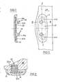
- Figur 1: Einen Längsschnitt durch ein Nasenplättchen gemäß einem ersten Ausführungsbeispiel in der Ebene I-I der Figur 2,
- Figur 2: eine Aufsicht auf das am Augenrand montierte Nasenplättchen gemäß Figur 1,
- Figur 3: einen Querschnitt durch das montierte Nasenplättchen gemäß Figur 1 in der Ebene III-III der Figur 2, und
- Figur 4-7: Darstellung eines Nasenplättchens gemäß einem zweiten Ausführungsbeispiel der Erfindung.
- Das Nasenplättchen besteht zunächst aus einem Grundkörper 10, der aus einem zähen, abriebfesten Material wie zum Beispiel Polycarbonat besteht und im wesentlichen als Flachteil ausgebildet ist, das mit einem mantelartigen Überzug 11 aus weichem Kunststoffmaterial, beispielsweise Silikon-Kautschuk überzogen ist. Im Grundkörper 10 sind Durchbrüche 10a,10b vorgesehen, durch die sich der Überzug 11 ebenfalls erstreckt und somit zusätzlich in seiner Position relativ zum Grundkörper 10 gehalten ist. Auf der Rückseite des Grundkörpers 10 erstrecken sich zwei gleich ausgebildete Verankerungsstifte 12,13 senkrecht zur Fläche des Grundkörpers 10. Diese Verankerungsstifte weisen eine Umfangsrinne 12a,13a in ihrem vorderen, aus dem Überzug 11 ragenden Teil auf.
- Diese Rinne 12a,13a in den Veerankerungsstiften 12,13 arbeitet zusammen mit einer Bohrung 22 im Augenrand 20. Diese Bohrung 22 besteht aus einem sich konusartig in Richtung des Überzuges 11 öffnenden, vorderen Teil und einem sich in Richtung zum Brillenglas erstreckenden, zylindrischen hinteren Teil, wobei im Übergangsbereich zwischen diesen beiden Teilen ein ebenfalls zylindrischer Bohrungsteil vorgesehen ist, der eine geringere lichte Weite als der genannte äußere Bohrungsteil aufweist, so daß eine umlaufende Ringschulter gebildet wird, bzw. unterhalb dieser Ringschulter eine Ringwulst 22a,23a, die so bemessen ist, daß sie so weit in die umlaufende Rinne 12a,13a der Verankerungsstifte 12,13 eingreift, daß diese von der Vorderseite her in die Bohrung eingerastet werden können. Die Länge der Verankerungsstifte 12,13 ist dabei so bemessen, daß die Verankerungsstifte nicht über den Augenrand im Bereich der jeweiligen Bohrung hinausstehen, sondern dort versenkt sind.Der zylindrische Übergangsbereich der beiden Bohrungshälften dient dazu, einen gewissen Toleranzbereich bei der Tiefe der inneren, zylindrischen Bohrung zu schaffen, ohne daß die Gefahr besteht, daß der Durchtrittsquerschnitt für das hintere Ende des Verankerungsstiftes zu groß wird, wenn der zylindrische Bohrungsteil zu weit in den konusförmigen Bohrungsteil hineingetrieben würde.
- Bei dem in den Figuren 1 bis 3 dargestellten ersten Ausführungsbeispiel sind zwei Verankerungsstifte 12,13 vorgesehen, die zusammen die erforderliche Doppelfunktion erfüllen, also die Sicherung des Nasenplättchens gegen Zug in der Längsachse der Verankerungsstifte einerseits, als auch die Sicherung des Nasenplättchens gegen Verdrehen in der Ebene des Grundkörpers 10.
- Bei dem in Figur 4 dargestellten zweiten Ausführungsbeispiel werden diese Funktionen verteilt, hier weist lediglich der mittlere Verankerungsstift 15 in Zusammenarbeit mit seiner zugehörigen Bohrung 25 die oben beschriebene Struktur auf und sichert somit das Nasenplättchen gegen Zug, wobei beidseits dieses Verankerungsstiftes 15 zwei weitere Verankerungsstifte 14 und 16 vorgesehen sind, die lediglich als zylindrische Zapfen ausgebildet sind und in entsprechende zylindrische Bohrungen im Augenrand einsteckbar sind. Letztere beiden Verankerungsstifte 14 und 16 dienen also lediglich der Sicherung des Nasenplättschens gegen Verdrehen.
- Es versteht sich von selbst, daß auch andere Kombinationen und Ausgestaltungen solcher Verankerungsstifte in Anpassung an die spezielle Situation ohne weiteres möglich sind.
Claims (9)
Priority Applications (1)
| Application Number | Priority Date | Filing Date | Title |
|---|---|---|---|
| AT88100655T ATE101929T1 (de) | 1987-03-06 | 1988-01-19 | Nasenplaettchen fuer brillen. |
Applications Claiming Priority (2)
| Application Number | Priority Date | Filing Date | Title |
|---|---|---|---|
| DE3707297 | 1987-03-06 | ||
| DE19873707297 DE3707297A1 (de) | 1987-03-06 | 1987-03-06 | Nasenplaettchen fuer brillen |
Publications (3)
| Publication Number | Publication Date |
|---|---|
| EP0280855A2 true EP0280855A2 (de) | 1988-09-07 |
| EP0280855A3 EP0280855A3 (en) | 1990-04-25 |
| EP0280855B1 EP0280855B1 (de) | 1994-02-23 |
Family
ID=6322464
Family Applications (1)
| Application Number | Title | Priority Date | Filing Date |
|---|---|---|---|
| EP88100655A Expired - Lifetime EP0280855B1 (de) | 1987-03-06 | 1988-01-19 | Nasenplättchen für Brillen |
Country Status (6)
| Country | Link |
|---|---|
| US (1) | US4904076A (de) |
| EP (1) | EP0280855B1 (de) |
| JP (1) | JP2823198B2 (de) |
| AT (1) | ATE101929T1 (de) |
| DE (2) | DE3707297A1 (de) |
| ES (1) | ES2050123T3 (de) |
Families Citing this family (18)
| Publication number | Priority date | Publication date | Assignee | Title |
|---|---|---|---|---|
| JPH0377934U (de) * | 1989-11-30 | 1991-08-06 | ||
| DE9106837U1 (de) * | 1991-06-04 | 1991-08-08 | Schimpf, Karl-Heinz, 7136 Ötisheim | Brillenbügel oder Bügelende aus thermoplastischem Kunststoff |
| DE4402983A1 (de) * | 1994-02-01 | 1995-08-03 | Frey & Winkler | Halterung für Nasenpads an einem Brillengestell |
| US6929364B1 (en) * | 1995-04-04 | 2005-08-16 | Oakley, Inc. | Contoured metal eyeglass frames |
| US6056399A (en) * | 1997-01-29 | 2000-05-02 | Oakley, Inc. | Interchangeable nosepiece system |
| US5872612A (en) * | 1998-01-13 | 1999-02-16 | The Hilsinger Company Lp | Dual-purpose nose pad insert assembly |
| WO2006111984A1 (en) * | 2005-04-18 | 2006-10-26 | SAFILO Società Azionaria Fabbrica Italiana Lavorazione | Nasal support pad for spectacle frames and spectacles including said pad |
| US7448750B2 (en) * | 2006-09-22 | 2008-11-11 | Oakley, Inc. | Quadrilateral lens |
| USD837871S1 (en) | 2017-09-01 | 2019-01-08 | Roka Sports, Inc. | Sport eyeglasses |
| WO2019075089A1 (en) | 2017-10-11 | 2019-04-18 | Roka Sports, Inc. | INTERCHANGEABLE LENS GLASSES |
| USD849823S1 (en) | 2018-03-13 | 2019-05-28 | Roka Sports, Inc. | Sport eyeglasses |
| USD849825S1 (en) | 2018-03-13 | 2019-05-28 | Roka Sports, Inc. | Sport eyeglasses |
| USD870802S1 (en) | 2018-03-28 | 2019-12-24 | Roka Sports, Inc. | Sport eyeglasses |
| USD871497S1 (en) | 2018-04-06 | 2019-12-31 | Roka Sports, Inc | Eyeglass temples |
| USD912722S1 (en) | 2018-04-06 | 2021-03-09 | Roka Sports, Inc. | Snap-in nose pads for eyewear |
| EP4042235A4 (de) * | 2019-10-11 | 2023-12-20 | Looloops, LLC | Rutschfestes brillensystem mit komfortsitz |
| US20210278698A1 (en) * | 2020-03-04 | 2021-09-09 | LooLoops, LLC | Comfort fit slip-resistant eyewear system |
| TWM650252U (zh) * | 2023-10-06 | 2024-01-01 | 華美光學科技股份有限公司 | 可拆卸鼻墊 |
Family Cites Families (19)
| Publication number | Priority date | Publication date | Assignee | Title |
|---|---|---|---|---|
| DE510758C (de) * | 1928-03-31 | 1930-10-23 | Percy Kirk | Augenglas |
| US1930556A (en) * | 1931-05-01 | 1933-10-17 | Arthur R Hilsinger | Nose-guard pad for eyeglasses |
| US2020265A (en) * | 1933-10-16 | 1935-11-05 | Sadler Bros Inc | Ophthalmic mounting |
| US2065098A (en) * | 1934-03-10 | 1936-12-22 | Menrad Ferdinand | Method of making plaquets for spectacles or eye-glasses |
| US2082084A (en) * | 1936-02-25 | 1937-06-01 | Tanasso Vincent | Nose pad coupling means for eyeglass frames |
| DE757047C (de) * | 1938-07-26 | 1954-07-12 | Theodor Kaehne & Soehne | Brille mit einsetzbaren Seitenstegen |
| GB516759A (en) * | 1939-04-24 | 1940-01-10 | American Optical Corp | Improvements in mountings for eyeglasses |
| DE1122736B (de) * | 1957-09-17 | 1962-01-25 | Paul Jaehrling | Nasenseitenauflage aus druckminderndem, elastischem Material wie Schwammgummi od. dgl fuer Brillengestelle aus Kunststoff oder aehnlichem Material ohne eigene harte Seitenstege |
| JPS5186437U (de) * | 1974-12-28 | 1976-07-10 | ||
| JPS52170543U (de) * | 1976-06-18 | 1977-12-24 | ||
| JPS5379544U (de) * | 1976-12-03 | 1978-07-03 | ||
| DE2750910A1 (de) * | 1977-11-14 | 1979-05-17 | Nitsche & Guenther Optische We | Seitenstegplaettchen mit weicher nasenauflage fuer brillenfassungen |
| DE3303749A1 (de) * | 1983-02-04 | 1984-08-09 | Ferdinand Wagner GmbH & Co, 7530 Pforzheim | Padbefestigung |
| DE3319827A1 (de) * | 1983-06-01 | 1984-12-06 | Marwitz & Hauser GmbH, 7000 Stuttgart | Brille |
| JPS6022117A (ja) * | 1983-07-18 | 1985-02-04 | Shiyaruman Megane:Kk | 合成樹脂メガネフレ−ムにおけるアジヤスタブルクリンガ−パツド,およびこれに用いるア−ム |
| DE3345992C1 (de) * | 1983-12-20 | 1984-08-16 | Optische Werke G. Rodenstock, 8000 München | Weicher Brillen-Sattelsteg |
| DE3417255A1 (de) * | 1984-05-10 | 1985-11-14 | Herbert 7531 Eisingen Speer | Halterung fuer pads |
| JPS61127939A (ja) * | 1984-11-26 | 1986-06-16 | Kawasaki Heavy Ind Ltd | エンジンのバランサ |
| DE3533641A1 (de) * | 1985-09-20 | 1987-04-02 | Josef Rocek | Nasenauflage fuer brillen, insbesondere in form eines pads |
-
1987
- 1987-03-06 DE DE19873707297 patent/DE3707297A1/de not_active Withdrawn
-
1988
- 1988-01-19 DE DE88100655T patent/DE3887908D1/de not_active Expired - Fee Related
- 1988-01-19 EP EP88100655A patent/EP0280855B1/de not_active Expired - Lifetime
- 1988-01-19 AT AT88100655T patent/ATE101929T1/de not_active IP Right Cessation
- 1988-01-19 ES ES88100655T patent/ES2050123T3/es not_active Expired - Lifetime
- 1988-03-04 US US07/164,469 patent/US4904076A/en not_active Expired - Lifetime
- 1988-03-07 JP JP63051814A patent/JP2823198B2/ja not_active Expired - Fee Related
Also Published As
| Publication number | Publication date |
|---|---|
| EP0280855A3 (en) | 1990-04-25 |
| JPS63231312A (ja) | 1988-09-27 |
| US4904076A (en) | 1990-02-27 |
| EP0280855B1 (de) | 1994-02-23 |
| DE3707297A1 (de) | 1988-09-15 |
| ATE101929T1 (de) | 1994-03-15 |
| DE3887908D1 (de) | 1994-03-31 |
| ES2050123T3 (es) | 1994-05-16 |
| JP2823198B2 (ja) | 1998-11-11 |
Similar Documents
| Publication | Publication Date | Title |
|---|---|---|
| EP0280855B1 (de) | Nasenplättchen für Brillen | |
| EP0400224B1 (de) | Enossales Einzelzahnimplantat sowie Konterwerkzeug zur Verwendung bei einem derartigen Implantat | |
| DE2723850A1 (de) | Moebelscharnier | |
| DE19509118A1 (de) | Zahnimplantatanordnung | |
| DE7906391U1 (de) | Nasenteil fuer brillengestell und entsprechendes brillengestell | |
| DE3609130A1 (de) | Padsystem | |
| CH697669B1 (de) | Uhr. | |
| DE3429089C2 (de) | Brille mit Brücke und Stegstützen | |
| WO1997019384A1 (de) | Randloser vorhänger für brillen | |
| DE2906516A1 (de) | Brillenscharnier | |
| DE3521296C2 (de) | Ohrbügel für Brillengestelle | |
| WO1985002913A1 (fr) | Pont de lunettes mou | |
| DE3506073C2 (de) | ||
| DE3419509A1 (de) | Buegelende eines brillenbuegels | |
| EP0899601B1 (de) | Brillenglashalterung | |
| DE29801490U1 (de) | Verbinder für einen Profilzylinder | |
| DE69213206T2 (de) | Schraubsicherungsmechanismus für Brille | |
| DE3403569A1 (de) | Padbefestigung fuer brillenfassungen | |
| DE69923293T2 (de) | Türgriff für elektrische Geräte, insbesondere für Kühlschränke | |
| EP0255508A2 (de) | Brillenscharnier | |
| DE4400163C2 (de) | Verbindungssystem für Scheren | |
| DE2550254C3 (de) | Hilfsgerät zur Anwendung beim Einträufeln von Augentropfen | |
| DE2549727A1 (de) | Kunststoff-moebelbeschlagteil | |
| DE29600441U1 (de) | Brillenbügel | |
| DE9114045U1 (de) | Schraubsicherung für Schließblöcke an Brillenfassungen |
Legal Events
| Date | Code | Title | Description |
|---|---|---|---|
| PUAI | Public reference made under article 153(3) epc to a published international application that has entered the european phase |
Free format text: ORIGINAL CODE: 0009012 |
|
| AK | Designated contracting states |
Kind code of ref document: A2 Designated state(s): AT DE ES FR GB IT |
|
| ITCL | It: translation for ep claims filed |
Representative=s name: CALVANI SALVI VERONELLI |
|
| PUAL | Search report despatched |
Free format text: ORIGINAL CODE: 0009013 |
|
| AK | Designated contracting states |
Kind code of ref document: A3 Designated state(s): AT DE ES FR GB IT |
|
| 17P | Request for examination filed |
Effective date: 19900515 |
|
| 17Q | First examination report despatched |
Effective date: 19920917 |
|
| GRAA | (expected) grant |
Free format text: ORIGINAL CODE: 0009210 |
|
| AK | Designated contracting states |
Kind code of ref document: B1 Designated state(s): AT DE ES FR GB IT |
|
| REF | Corresponds to: |
Ref document number: 101929 Country of ref document: AT Date of ref document: 19940315 Kind code of ref document: T |
|
| REF | Corresponds to: |
Ref document number: 3887908 Country of ref document: DE Date of ref document: 19940331 |
|
| REG | Reference to a national code |
Ref country code: ES Ref legal event code: FG2A Ref document number: 2050123 Country of ref document: ES Kind code of ref document: T3 |
|
| ITF | It: translation for a ep patent filed | ||
| ET | Fr: translation filed | ||
| GBT | Gb: translation of ep patent filed (gb section 77(6)(a)/1977) |
Effective date: 19940527 |
|
| PLBE | No opposition filed within time limit |
Free format text: ORIGINAL CODE: 0009261 |
|
| STAA | Information on the status of an ep patent application or granted ep patent |
Free format text: STATUS: NO OPPOSITION FILED WITHIN TIME LIMIT |
|
| 26N | No opposition filed | ||
| PGFP | Annual fee paid to national office [announced via postgrant information from national office to epo] |
Ref country code: DE Payment date: 20011120 Year of fee payment: 15 |
|
| REG | Reference to a national code |
Ref country code: GB Ref legal event code: IF02 |
|
| PGFP | Annual fee paid to national office [announced via postgrant information from national office to epo] |
Ref country code: GB Payment date: 20020102 Year of fee payment: 15 |
|
| PGFP | Annual fee paid to national office [announced via postgrant information from national office to epo] |
Ref country code: AT Payment date: 20020123 Year of fee payment: 15 |
|
| PGFP | Annual fee paid to national office [announced via postgrant information from national office to epo] |
Ref country code: FR Payment date: 20020124 Year of fee payment: 15 |
|
| PGFP | Annual fee paid to national office [announced via postgrant information from national office to epo] |
Ref country code: ES Payment date: 20020205 Year of fee payment: 15 |
|
| PG25 | Lapsed in a contracting state [announced via postgrant information from national office to epo] |
Ref country code: GB Free format text: LAPSE BECAUSE OF NON-PAYMENT OF DUE FEES Effective date: 20030119 Ref country code: AT Free format text: LAPSE BECAUSE OF NON-PAYMENT OF DUE FEES Effective date: 20030119 |
|
| PG25 | Lapsed in a contracting state [announced via postgrant information from national office to epo] |
Ref country code: ES Free format text: LAPSE BECAUSE OF NON-PAYMENT OF DUE FEES Effective date: 20030120 |
|
| PG25 | Lapsed in a contracting state [announced via postgrant information from national office to epo] |
Ref country code: DE Free format text: LAPSE BECAUSE OF NON-PAYMENT OF DUE FEES Effective date: 20030801 |
|
| GBPC | Gb: european patent ceased through non-payment of renewal fee | ||
| PG25 | Lapsed in a contracting state [announced via postgrant information from national office to epo] |
Ref country code: FR Free format text: LAPSE BECAUSE OF NON-PAYMENT OF DUE FEES Effective date: 20030930 |
|
| REG | Reference to a national code |
Ref country code: FR Ref legal event code: ST |
|
| REG | Reference to a national code |
Ref country code: ES Ref legal event code: FD2A Effective date: 20030120 |
|
| PG25 | Lapsed in a contracting state [announced via postgrant information from national office to epo] |
Ref country code: IT Free format text: LAPSE BECAUSE OF NON-PAYMENT OF DUE FEES;WARNING: LAPSES OF ITALIAN PATENTS WITH EFFECTIVE DATE BEFORE 2007 MAY HAVE OCCURRED AT ANY TIME BEFORE 2007. THE CORRECT EFFECTIVE DATE MAY BE DIFFERENT FROM THE ONE RECORDED. Effective date: 20050119 |