EP0280694B1 - Vorrichtung zum zusammenführen und ablegen von gefalzten druckprodukten in schuppenformation auf eine fördereinrichtung - Google Patents
Vorrichtung zum zusammenführen und ablegen von gefalzten druckprodukten in schuppenformation auf eine fördereinrichtung Download PDFInfo
- Publication number
- EP0280694B1 EP0280694B1 EP19870904803 EP87904803A EP0280694B1 EP 0280694 B1 EP0280694 B1 EP 0280694B1 EP 19870904803 EP19870904803 EP 19870904803 EP 87904803 A EP87904803 A EP 87904803A EP 0280694 B1 EP0280694 B1 EP 0280694B1
- Authority
- EP
- European Patent Office
- Prior art keywords
- drum
- compartments
- groups
- section
- compartment
- Prior art date
- Legal status (The legal status is an assumption and is not a legal conclusion. Google has not performed a legal analysis and makes no representation as to the accuracy of the status listed.)
- Expired - Lifetime
Links
Images
Classifications
-
- B—PERFORMING OPERATIONS; TRANSPORTING
- B65—CONVEYING; PACKING; STORING; HANDLING THIN OR FILAMENTARY MATERIAL
- B65H—HANDLING THIN OR FILAMENTARY MATERIAL, e.g. SHEETS, WEBS, CABLES
- B65H29/00—Delivering or advancing articles from machines; Advancing articles to or into piles
- B65H29/66—Advancing articles in overlapping streams
- B65H29/6681—Advancing articles in overlapping streams merging two or more streams into an overlapping stream
-
- B—PERFORMING OPERATIONS; TRANSPORTING
- B65—CONVEYING; PACKING; STORING; HANDLING THIN OR FILAMENTARY MATERIAL
- B65H—HANDLING THIN OR FILAMENTARY MATERIAL, e.g. SHEETS, WEBS, CABLES
- B65H29/00—Delivering or advancing articles from machines; Advancing articles to or into piles
- B65H29/38—Delivering or advancing articles from machines; Advancing articles to or into piles by movable piling or advancing arms, frames, plates, or like members with which the articles are maintained in face contact
- B65H29/40—Members rotated about an axis perpendicular to direction of article movement, e.g. star-wheels formed by S-shaped members
-
- B—PERFORMING OPERATIONS; TRANSPORTING
- B65—CONVEYING; PACKING; STORING; HANDLING THIN OR FILAMENTARY MATERIAL
- B65H—HANDLING THIN OR FILAMENTARY MATERIAL, e.g. SHEETS, WEBS, CABLES
- B65H29/00—Delivering or advancing articles from machines; Advancing articles to or into piles
- B65H29/66—Advancing articles in overlapping streams
- B65H29/6609—Advancing articles in overlapping streams forming an overlapping stream
-
- B—PERFORMING OPERATIONS; TRANSPORTING
- B65—CONVEYING; PACKING; STORING; HANDLING THIN OR FILAMENTARY MATERIAL
- B65H—HANDLING THIN OR FILAMENTARY MATERIAL, e.g. SHEETS, WEBS, CABLES
- B65H2301/00—Handling processes for sheets or webs
- B65H2301/40—Type of handling process
- B65H2301/44—Moving, forwarding, guiding material
- B65H2301/447—Moving, forwarding, guiding material transferring material between transport devices
- B65H2301/4473—Belts, endless moving elements on which the material is in surface contact
- B65H2301/44732—Belts, endless moving elements on which the material is in surface contact transporting articles in overlapping stream
-
- B—PERFORMING OPERATIONS; TRANSPORTING
- B65—CONVEYING; PACKING; STORING; HANDLING THIN OR FILAMENTARY MATERIAL
- B65H—HANDLING THIN OR FILAMENTARY MATERIAL, e.g. SHEETS, WEBS, CABLES
- B65H2301/00—Handling processes for sheets or webs
- B65H2301/40—Type of handling process
- B65H2301/44—Moving, forwarding, guiding material
- B65H2301/447—Moving, forwarding, guiding material transferring material between transport devices
- B65H2301/44765—Rotary transport devices with compartments
Definitions
- the invention relates to a device for merging and depositing folded printed products in scale formation on a conveying device, having a cylindrical drum which can be rotated about a horizontal axis and which is equipped with a plurality of compartments which open to the drum circumference and are curved in the drum cross section to accommodate one folded printed product each. the printed products are fed individually to the compartments on the drum circumference and placed on the conveyor in the lower half of the drum rotation.
- Devices of this type which are used to form a shingled stream, are predominantly used in folders of printing machines in order to receive the printed products folded by folding cylinders and to deposit them one after the other in shingled formation on a conveyor belt.
- the invention aims to provide a device of the type specified in the introduction, which makes it possible to combine the products obtained from the two folding apparatuses into a single row placed in a scale formation, in order in this way to arrange the downstream ones. To have to provide further processing machines only once.
- the device according to the invention is characterized in that the compartments of the drum are arranged side by side in two groups in the longitudinal direction of the drum and the compartments of the two groups alternate in the circumferential direction of the drum, the compartments of each group moving inwards from a drum end face in alignment with an associated printed product feed device extend and the compartments of the other group overlap in a central section corresponding to the size of a printed product, and that each compartment is provided with a slide which can be moved parallel to the drum axis and is biased against the drum end face and which is operated by a scanner running on a control curve during a Section of the drum rotation with displacement of the printed product in the overlap section of the two compartment groups against the longitudinal center of the drum is movable.
- This construction makes it possible to combine the printed products emerging from two parallel folding devices in the form of a shingled stream into a single shingled stream.
- the high processing speed of the downstream processing machines can be exploited, e.g. up to 2 x 60,000 products / h, therefore can be up to 120,000 products / h.
- each section is a cam or the like in the area of entry of the individual printed products into the compartments. assigned to lifting the leading edge of each printed product in order to prevent the printed product from bumping against a compartment edge.
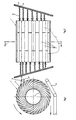
- the device has a rotatably mounted drum 1 with a cylindrical core 1 'and compartments 2 which extend radially away from it and have a substantially U-shaped cross section and open towards the drum circumference.
- the compartments 2 are arranged side by side over the drum length in two groups, the compartments of each group extending inwards from one end face of the drum and the compartments of the other group overlapping in a central drum section which corresponds to the width of a printed product.
- the compartments 2 of the two groups are thus arranged alternately in the drum circumferential direction.
- a closed drum section 3 is provided next to each compartment of the one group and extends to the other end of the drum.
- the folded printed products D which leave the folders (not shown) on conveyors in two parallel rows, are fed to the compartments 2 essentially horizontally in an upper drum peripheral section.
- the leading edges of the printed products D are raised immediately before entering the compartments by means of a cam 4, so that they do not hit the boundary edge of the neighboring compartments; In this way, the individual printed products enter the subjects of the assigned subject groups one after the other.
- the slide 5 is actuated by a scanner 6, which is on a of the drum end face associated control cam 7, which causes the slide 5 during the drum rotation in. Tray is pushed inwards towards the transverse median plane of the drum.
- the printed products D contained in the compartments are centered in a row with respect to the transverse median plane of the drum and slide in the lower section the rotation of the drum under the action of gravity from the compartments 2 onto a downstream conveyor belt 8, on which they come to rest in scale formation.
Landscapes
- Engineering & Computer Science (AREA)
- Mechanical Engineering (AREA)
- Collation Of Sheets And Webs (AREA)
- Folding Of Thin Sheet-Like Materials, Special Discharging Devices, And Others (AREA)
Description
- Die Erfindung betrifft eine Vorrichtung zum Zusammenführen und Ablegen von gefalzten Druckprodukten in Schuppenformation auf eine Fördereinrichtung, mit einer um eine horizontale Achse drehbaren zylindrischen Trommel, die mit mehreren, sich zum Trommelumfang öffnenden, im Trommelquerschnitt gekrümmten Fächern zur Aufnahme je eines gefalzten Druckproduktes ausgestattet ist, wobei die Druckprodukte den Fächern am Trommelumfang vereinzelt zugeführt und in der unteren Hälfte der Trommeldrehung auf die Fördereinrichtung abgelegt werden.
- Vorrichtungen dieser Art, die zur Bildung eines Schuppenstromes dienen, werden vorwiegend in Falzapparaten von Druckmaschinen eingesetzt, um die von Falzzylindern gefalzten Druckprodukte aufzunehmen und nacheinander in Schuppenformation auf ein Förderband abzulegen.
- Um die Produktion zu steigern, erfolgt bei Rollen-Rotationsdruckmaschinen eine Doppelproduktion über zwei Falzapparate, was zur Folge hat, daß zwei Ströme von schuppenförmig gelegten Druckprodukten die Druckmaschine verlassen und alle nachgeschalteten Weiterverarbeitungsmaschinen in doppelter Zahl parallelgeschaltet vorgesehen werden müssen, was mit beträchtlichen Anlagen-, Bedienungs- und Wartungskosten verbunden ist und die Störanfälligkeit erhöht.
- Die Erfindung zielt darauf ab, eine Vorrichtung der einleitend angegebenen Art zu schaffen, die es ermöglicht, die aus den beiden Falzapparaten anfallenden Produkte zu einer einzigen in Schuppenformation gelegten Reihe zusammenzuführen, um auf diese Weise die nachgeschalteten. Weiterverarbeitungsmaschinen nur ein Mal vorsehen zu mussen.
- Die erfindungsgemäße Vorrichtung zeichnet sich dadurch aus, daß die Fächer der Trommel in Trommellängsrichtung in zwei Gruppen nebeneinander angeordnet sind und die Fächer der beiden Gruppen einander in Trommelumfangsrichtung abwechseln, wobei die Fächer jeder Gruppe sich von einer Trommelstirnseite in Ausrichtung mit einer zugeordneten Druckprodukt-Zuführeinrichtung einwärts erstrecken und die Fächer der anderen Gruppe in einem mittleren, der Größe eines Druckproduktes entsprechenden Abschnitt überlappen, und daß jedes Fach mit einem parallel zur Trommelachse bewegbaren, gegen die Trommelstirnseite vorgespannten Schieber versehen ist, der von einem trommelstirnseitigen, auf einer Steuerkurve ablaufenden Abtaster während eines Abschnittes der Trommeldrehung unter Verschiebung des Druckproduktes in den Uberlappungsabschnitt der beiden Fachgruppen gegen die Trommellängsmitte hin bewegbar ist.
- Diese Konstruktion ermöglicht es, die aus zwei parallelgeschalteten Falzapparaten in Form je eines Schuppenstromes austretenden Druckprodukte zu einem einzigen Schuppenstrom zusammenzuführen. Auf diese Weise kann die hohe Verarbeitungsgeschwindigkeit der nachgeschalteten Weiterverarbeitungsmaschinen ausgenützt werden, die z.B. bis zu 2 x 60.000 Produkte/h, daher bis zu 120.000 Produkte/h betragen kann.
- Gemäß einer bevorzugten Ausführungsform der Erfindung ist jeder Fachgruppe im Bereich des Eintrittes der vereinzelten Druckprodukte in die Fächer ein Nocken od.dgl. zum Anheben der Vorderkante jedes Druckproduktes zugeordnet, um ein Anstoßen des Druckproduktes an einer Fachkante zu vermeiden.
- Weitere Merkmale der Erfindung werden nachfolgend an einem Ausführungsbeispiel unter Bezugnahme auf die Zeichnungen näher erläutert, in denen.
-
- Figur 1 einen schematischen Schnitt einer erfindungsgemäßen Vorrichtung nach der Linie I-I in Figur 2,
- Figur 2 eine schematische Stirnansicht der Vorrichtung und
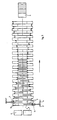
- Figur 3 eine schematische Abwicklung der Darstellung nach Figur 2 zeigen.
- Die Vorrichtung weist eine drehbar gelagerte Trommel 1 mit einem zylindrischen Kern l' und sich von diesem gekrümmt radial wegerstreckenden Fächern 2 auf, die im wesentlichen U-förmigen Querschnitt haben und sich zum Trommelumfang hin öffnen. Die Fächer 2 sind über die Trommellänge in zwei Gruppen nebeneinander angeordnet, wobei die Fächer jeder Gruppe sich von einer Trommelstirnseite her einwärts erstrekken und die Fächer der anderen Gruppe in einem mittleren Trommelabschnitt überlappen, welcher der Breite eines Druckproduktes entspricht. Die Fächer 2 der beiden Gruppen sind somit in Trommelumfangsrichtung abwechselnd angeordnet.
- Wie Figur 2 zeigt, ist in Richtung der Trommelachse neben jedem Fach der einen Gruppe ein geschlossener Trommelabschnitt 3 vorgesehen, der sich bis zur anderen Trommelstirnseite erstreckt. Die gefalzten Druckprodukte D, welche die nicht gezeigten Falzapparate auf Fördereinrichtungen in zwei parallelen Reihen verlassen, werden den Fächern 2 in einem oberen Trommelumfangsabschnitt im wesentlichen horizontal zugeführt. Die Vorderkanten der Druckprodukte D werden unmittelbar vor dem Eintritt in die Fächer mittels eines Nockens 4 angehoben, damit sie nicht gegen die Begrenzungskante der benachbarten Fächer stoßen; auf diese Weise treten die vereinzelten Druckprodukte nacheinander in die Fächer der zugeordneten Fachgruppen ein.
- Wie aus den Figuren 2 und 3 ferner hervorgeht, ist in jedem Fach 2 ein gegen die Trommelstirnseite federnd vorgespannter Schieber 5 angeordnet, der an dem in das Fach eingetretenen Druckprodukt D seitlich angreift, Der Schieber 5 wird von einem Abtaster 6 betätigt, der auf einer der Trommelstirnseite zugeordneten Steuerkurve 7 abrollt, die bewirkt daß der Schieber 5 während der Trommeldrehun im. Fach fortschreitend nach innen in Richtung auf die Quermittelebene der Trommel geschoben wird. Dadurch werden die in den Fächern enthaltenen Druckprodukte D bezüglich der Quermittelebene der Trommel in einer Reihe zentriert und gleiten im unteren Abschnitt der Trommeldrehung unter Schwerkraftwirkung aus den Fächern 2 auf ein nachgeschaltetes Förderband 8, auf dem sie in Schuppenformation zu liegen kommen.
- Es versteht sich, daß das dargestellte und beschriebene Ausführungsbeispiel im Rahmen des allgemeinen Erfindungsgedankens hinsichtlich der konstruktiven Einzelheiten, speziell der Schieber und deren Führung, und zur Unterstützung der Schwerkraftwirkung beim Austritt der Druckprodukte aus den Fächern durch mechanische Mittel verschiedentlich abgewandelt werden kann.
Claims (3)
Applications Claiming Priority (2)
| Application Number | Priority Date | Filing Date | Title |
|---|---|---|---|
| AT212486A AT385747B (de) | 1986-08-06 | 1986-08-06 | Vorrichtung zum zusammenfuehren und ablegen von gefalzten druckprodukten in schuppenformation auf eine foerdereinrichtung |
| AT2124/86 | 1986-08-06 |
Publications (2)
| Publication Number | Publication Date |
|---|---|
| EP0280694A1 EP0280694A1 (de) | 1988-09-07 |
| EP0280694B1 true EP0280694B1 (de) | 1990-10-24 |
Family
ID=3528291
Family Applications (1)
| Application Number | Title | Priority Date | Filing Date |
|---|---|---|---|
| EP19870904803 Expired - Lifetime EP0280694B1 (de) | 1986-08-06 | 1987-08-04 | Vorrichtung zum zusammenführen und ablegen von gefalzten druckprodukten in schuppenformation auf eine fördereinrichtung |
Country Status (5)
| Country | Link |
|---|---|
| EP (1) | EP0280694B1 (de) |
| AT (1) | AT385747B (de) |
| DK (1) | DK164695C (de) |
| FI (1) | FI87341C (de) |
| WO (1) | WO1988000919A1 (de) |
Families Citing this family (4)
| Publication number | Priority date | Publication date | Assignee | Title |
|---|---|---|---|---|
| DE59503661D1 (de) * | 1994-05-04 | 1998-10-29 | Ferag Ag | Verfahren zum Verarbeiten von Druckereiprodukten |
| JPH07309496A (ja) * | 1994-05-16 | 1995-11-28 | Riso Kagaku Corp | 印刷機の排紙装置 |
| DE19950354C1 (de) * | 1999-10-19 | 2001-06-07 | Boewe Systec Ag | Verfahren und Vorrichtung zum Bilden von Blattgruppen aus einer Mehrzahl von Blättern |
| EP2275373B1 (de) * | 2009-07-16 | 2012-12-26 | Müller Martini Holding AG | Verfahren und Vorrichtung zum kontinuierlichen Zusammenführen von zumindest zwei Schuppenströmen flächiger Druckprodukte |
Family Cites Families (2)
| Publication number | Priority date | Publication date | Assignee | Title |
|---|---|---|---|---|
| US3271023A (en) * | 1963-12-30 | 1966-09-06 | Gen Foods Corp | Sheet collating apparatus |
| CH584153A5 (de) * | 1973-10-10 | 1977-01-31 | Ferag Ag |
-
1986
- 1986-08-06 AT AT212486A patent/AT385747B/de not_active IP Right Cessation
-
1987
- 1987-08-04 EP EP19870904803 patent/EP0280694B1/de not_active Expired - Lifetime
- 1987-08-04 WO PCT/AT1987/000047 patent/WO1988000919A1/de active IP Right Grant
-
1988
- 1988-03-21 FI FI881332A patent/FI87341C/fi not_active IP Right Cessation
- 1988-03-24 DK DK161188A patent/DK164695C/da not_active IP Right Cessation
Also Published As
| Publication number | Publication date |
|---|---|
| EP0280694A1 (de) | 1988-09-07 |
| FI881332A (fi) | 1988-03-21 |
| AT385747B (de) | 1988-05-10 |
| ATA212486A (de) | 1987-10-15 |
| FI881332A0 (fi) | 1988-03-21 |
| FI87341B (fi) | 1992-09-15 |
| DK164695C (da) | 1992-12-21 |
| FI87341C (fi) | 1992-12-28 |
| DK161188A (da) | 1988-03-24 |
| DK161188D0 (da) | 1988-03-24 |
| DK164695B (da) | 1992-08-03 |
| WO1988000919A1 (en) | 1988-02-11 |
Similar Documents
| Publication | Publication Date | Title |
|---|---|---|
| DE3620945C2 (de) | Vorrichtung zum Sammeln von gefalzten Druckbogen | |
| EP0208081B1 (de) | Verfahren und Vorrichtung zum Öffnen von ausserhalb der Mitte gefalteten Druckprodukten | |
| CH652106A5 (de) | Verfahren und vorrichtung zum bilden von einzelnen stapeln aus einer endlosen bahn. | |
| DE3603285C2 (de) | Zusammentragmaschine | |
| DE1013156B (de) | Verfahren und Vorrichtung zum Foerdern von Blaettern in Papier od. dgl. verarbeitenden Maschinen | |
| DE3413952C2 (de) | ||
| EP0265735B1 (de) | Verfahren und Vorrichtung zum Übernehmen von gefalzten Druckereierzeugnissen von Druckmaschinen | |
| DE1761636A1 (de) | Vorrichtung zum Ausrichten und mit der Spitze abwaerts zeigenden Einbringen von Eiern in Aufnahmetaschen besitzende Transportmittel | |
| DE3009927C2 (de) | Einrichtung zum Abziehen und insbesondere Vereinigen von biegsamen Flächengebilden, insbesondere Bogen oder Druckprodukten aus mindestens zwei Stapeln | |
| DE3330681C2 (de) | ||
| EP0280694B1 (de) | Vorrichtung zum zusammenführen und ablegen von gefalzten druckprodukten in schuppenformation auf eine fördereinrichtung | |
| EP0755886A1 (de) | Vorrichtung zum Zubringen von Druckereiprodukten zu einer Weiterverarbeitungsstelle | |
| DE2832660B2 (de) | Vorrichtung zum gruppenweisen Abteilen von geschuppt übereinanderliegend geförderten Werkstücken | |
| DE2452050C2 (de) | Vorrichtung zum passergerechten Anlegen von Bogen in Bogenrotationsdruckmaschinen | |
| AT401740B (de) | Vorrichtung zum trennen von flächig und räumlich ausgeprägten körpern | |
| DE4030643C2 (de) | ||
| DE1510218B2 (de) | Vorrichtung zum kontinuierlichen Entwirren und Ausrichten von textlien Rohfasern | |
| DE2720275A1 (de) | Maschine zur behandlung von behaeltern und insbesondere glasflaschen, die auf einem foerderband kontinuierlich durchlaufen | |
| DE3344114C2 (de) | Zusammentragmaschine | |
| DE19540711C2 (de) | Vorrichtung für die Freigabe von Falzprodukten | |
| EP0806391A1 (de) | Vorrichtung zum Zubringen von Druckereierzeugnissen zu einer Weiterverarbeitungsstelle | |
| DE4436075A1 (de) | Vorrichtung zum Palettieren von Stückgütern zu einem Stückgutstapel | |
| DE2601616C3 (de) | Vorrichtung zum Verteilen von Bogen in Sammelfächer | |
| DE2453530C2 (de) | Vorrichtung zum kontinuierlichen Übertragen von aufeinanderfolgenden Gegenständen von einer ersten auf eine zweite Festplatte | |
| DE477429C (de) | Stapelvorrichtung fuer die aus Bearbeitungsmaschinen von Papier, Pappe u. dgl. heraustretenden bearbeiteten Teile oder Stuecke |
Legal Events
| Date | Code | Title | Description |
|---|---|---|---|
| PUAI | Public reference made under article 153(3) epc to a published international application that has entered the european phase |
Free format text: ORIGINAL CODE: 0009012 |
|
| AK | Designated contracting states |
Kind code of ref document: A1 Designated state(s): AT BE CH DE FR GB IT LI LU NL SE |
|
| 17P | Request for examination filed |
Effective date: 19880721 |
|
| 17Q | First examination report despatched |
Effective date: 19891229 |
|
| GRAA | (expected) grant |
Free format text: ORIGINAL CODE: 0009210 |
|
| AK | Designated contracting states |
Kind code of ref document: B1 Designated state(s): AT BE CH DE FR GB IT LI LU NL SE |
|
| REF | Corresponds to: |
Ref document number: 57672 Country of ref document: AT Date of ref document: 19901115 Kind code of ref document: T |
|
| GBT | Gb: translation of ep patent filed (gb section 77(6)(a)/1977) | ||
| REF | Corresponds to: |
Ref document number: 3765775 Country of ref document: DE Date of ref document: 19901129 |
|
| ITF | It: translation for a ep patent filed |
Owner name: MODIANO & ASSOCIATI S.R.L. |
|
| ET | Fr: translation filed | ||
| PLBE | No opposition filed within time limit |
Free format text: ORIGINAL CODE: 0009261 |
|
| STAA | Information on the status of an ep patent application or granted ep patent |
Free format text: STATUS: NO OPPOSITION FILED WITHIN TIME LIMIT |
|
| ITTA | It: last paid annual fee | ||
| 26N | No opposition filed | ||
| PGFP | Annual fee paid to national office [announced via postgrant information from national office to epo] |
Ref country code: GB Payment date: 19920804 Year of fee payment: 6 |
|
| PGFP | Annual fee paid to national office [announced via postgrant information from national office to epo] |
Ref country code: SE Payment date: 19920811 Year of fee payment: 6 Ref country code: AT Payment date: 19920811 Year of fee payment: 6 |
|
| PGFP | Annual fee paid to national office [announced via postgrant information from national office to epo] |
Ref country code: CH Payment date: 19920813 Year of fee payment: 6 |
|
| PGFP | Annual fee paid to national office [announced via postgrant information from national office to epo] |
Ref country code: FR Payment date: 19920817 Year of fee payment: 6 |
|
| PGFP | Annual fee paid to national office [announced via postgrant information from national office to epo] |
Ref country code: DE Payment date: 19920820 Year of fee payment: 6 |
|
| PGFP | Annual fee paid to national office [announced via postgrant information from national office to epo] |
Ref country code: LU Payment date: 19920826 Year of fee payment: 6 |
|
| PGFP | Annual fee paid to national office [announced via postgrant information from national office to epo] |
Ref country code: BE Payment date: 19920827 Year of fee payment: 6 |
|
| PGFP | Annual fee paid to national office [announced via postgrant information from national office to epo] |
Ref country code: NL Payment date: 19920831 Year of fee payment: 6 |
|
| EPTA | Lu: last paid annual fee | ||
| PG25 | Lapsed in a contracting state [announced via postgrant information from national office to epo] |
Ref country code: LU Free format text: LAPSE BECAUSE OF NON-PAYMENT OF DUE FEES Effective date: 19930804 Ref country code: GB Effective date: 19930804 Ref country code: AT Effective date: 19930804 |
|
| PG25 | Lapsed in a contracting state [announced via postgrant information from national office to epo] |
Ref country code: SE Effective date: 19930805 |
|
| PG25 | Lapsed in a contracting state [announced via postgrant information from national office to epo] |
Ref country code: LI Effective date: 19930831 Ref country code: CH Effective date: 19930831 Ref country code: BE Effective date: 19930831 |
|
| BERE | Be: lapsed |
Owner name: LIEBE-HERZING GRAPHISCHE MASCHINEN K.G. Effective date: 19930831 |
|
| PG25 | Lapsed in a contracting state [announced via postgrant information from national office to epo] |
Ref country code: NL Effective date: 19940301 |
|
| GBPC | Gb: european patent ceased through non-payment of renewal fee |
Effective date: 19930804 |
|
| NLV4 | Nl: lapsed or anulled due to non-payment of the annual fee | ||
| PG25 | Lapsed in a contracting state [announced via postgrant information from national office to epo] |
Ref country code: FR Effective date: 19940429 |
|
| REG | Reference to a national code |
Ref country code: CH Ref legal event code: PL |
|
| PG25 | Lapsed in a contracting state [announced via postgrant information from national office to epo] |
Ref country code: DE Effective date: 19940503 |
|
| REG | Reference to a national code |
Ref country code: FR Ref legal event code: ST |
|
| EUG | Se: european patent has lapsed |
Ref document number: 87904803.1 Effective date: 19940310 |
|
| PG25 | Lapsed in a contracting state [announced via postgrant information from national office to epo] |
Ref country code: IT Free format text: LAPSE BECAUSE OF NON-PAYMENT OF DUE FEES Effective date: 20050804 |