EP0279870A1 - Vorrichtung zum Entleeren von Briefumschlägen - Google Patents
Vorrichtung zum Entleeren von Briefumschlägen Download PDFInfo
- Publication number
- EP0279870A1 EP0279870A1 EP87102460A EP87102460A EP0279870A1 EP 0279870 A1 EP0279870 A1 EP 0279870A1 EP 87102460 A EP87102460 A EP 87102460A EP 87102460 A EP87102460 A EP 87102460A EP 0279870 A1 EP0279870 A1 EP 0279870A1
- Authority
- EP
- European Patent Office
- Prior art keywords
- envelope
- transport plane
- plane
- table segment
- suction
- Prior art date
- Legal status (The legal status is an assumption and is not a legal conclusion. Google has not performed a legal analysis and makes no representation as to the accuracy of the status listed.)
- Granted
Links
- 238000003801 milling Methods 0.000 claims 1
- 238000009966 trimming Methods 0.000 abstract 1
- 241000252169 Catostomus commersonii Species 0.000 description 2
- 238000000926 separation method Methods 0.000 description 2
- 230000000694 effects Effects 0.000 description 1
- 230000002349 favourable effect Effects 0.000 description 1
- 230000001960 triggered effect Effects 0.000 description 1
Images


Classifications
-
- B—PERFORMING OPERATIONS; TRANSPORTING
- B65—CONVEYING; PACKING; STORING; HANDLING THIN OR FILAMENTARY MATERIAL
- B65B—MACHINES, APPARATUS OR DEVICES FOR, OR METHODS OF, PACKAGING ARTICLES OR MATERIALS; UNPACKING
- B65B69/00—Unpacking of articles or materials, not otherwise provided for
-
- B—PERFORMING OPERATIONS; TRANSPORTING
- B43—WRITING OR DRAWING IMPLEMENTS; BUREAU ACCESSORIES
- B43M—BUREAU ACCESSORIES NOT OTHERWISE PROVIDED FOR
- B43M7/00—Devices for opening envelopes
- B43M7/02—Devices for both opening envelopes and removing contents
Definitions
- the invention relates to a device according to the preamble of claim 1.
- a device is known from European Patent 0 036 94l.
- One suction arm of this known device can be moved not only perpendicularly to the envelope plane but also in the envelope plane, so that a relative movement between the envelope and the letter content is generated. This will further distort the envelope, i.e. curled so that it separates safely from the letter content and this can be easily removed. This is to prevent the entire content from being accidentally removed.
- DE-OS 27 32 936 which, however, does not open the possibility of additionally moving one suction arm in the envelope level.
- the invention is based on the object of creating a device of the type mentioned at the outset, with high removal and operational reliability, in order to ensure the emptying of envelopes in a wide variety of formats and also thicker and heavier envelopes.
- envelopes of different sizes e.g. 90 to 180 mm width
- different thicknesses up to 6 mm
- These horizontally moved envelopes are then pivoted up through the table segment in the area of the suction cups, so that the operator can see into the envelope opened by the suction cups without obstructing vision.
- the envelope lies securely on the table segment, even if it is a very thin envelope, for example an airmail envelope.
- the table segment supports the envelope in its actual removal position so that the suction cups can give it the shape that is particularly favorable for removal.
- the lower suction cup is practically firmly connected to the table segment and can therefore be moved together with it.
- This embodiment is simpler and therefore more economical to implement.
- the envelope is distorted, ie it receives one Waveform that differs from that of the content so that the content can be recognized, grasped and extracted safely. It is virtually impossible for the operator to miss the content.
- the additional movement in the envelope plane can advantageously be a tilting movement by a corresponding tilting angle.
- the suction arm carrying the suction cup is rotated about its longitudinal axis. This type of additional movement is effective and is easy to implement.
- the device shown in the drawing shows a removal device 1 and an under-table unit 2, in which the high-voltage part and the vacuum pump are accommodated.
- the removal device can also be used at a different location than the under-table unit.
- a work table 3 carries the removal device and an envelope tray. Furthermore, a sorting compartment is indicated by dash-dotted lines.
- the position 6 for the operator is in front of a removal area labeled 5.
- the envelopes 18 to be opened are arranged in a storage chute 7. They are removed from the storage shaft 7 by a suction device on a suction arm 8. It is controlled by a photocell 20.
- this part is followed by the essentially horizontal transport plane with a conveyor system.
- the cutting unit is labeled l0.
- the cutting tools are adjustable by an adjustment 29.
- the envelopes After being cut open, reach the actual removal station l2 in the transport device indicated by the arrow in FIG.
- the removal station is formed by two suction cups l5 and l6.
- the lower suction l5, which lies in the transport plane 9, is attached to a pivotable table segment l3.
- the upper suction l6 is attached to a suction arm l7.
- stops 14 are provided for different envelope sizes.
- a photocell 20 detects the removal of the envelope content 19 and thereby triggers the next removal cycle or machine cycle.
- a contact switch 24 is located opposite the upper sucker 16.
- a counter holder 25 is located opposite the lower suction cup l5, since the two suction cups l5 and l6 are offset from one another in the envelope plane.
- a projection 26 is provided on the table segment l3 adjacent to the lower suction cup l5.
- the table segment is pivotable about the longitudinal edge, which is parallel to the envelope guide edge 11 but away from it.
- the front edge of the table segment is pivoted approximately to the height of the removal surface 5.
- the envelopes l8 separated by means of the suction arm 8 and opened by the cutting unit 10 at the front edge are conveyed into the removal station l2 by the conveying device in the transport plane 9 until the corresponding stop 14.1 or 14.2 is reached.
- This position is clearly visible in Fig. 3.
- the photocell 22 determines the length of the corresponding envelope and controls the stops 14.1 or 14.2.
- the suction arm 17 with the upper suction device 16 is adjusted Arrival of the envelope in the removal station moves down on the envelope.
- the corresponding end position of the upper suction device 16 is determined by the contact switch 24, which controls the application of the vacuum and the further movements.
- the table segment l3 with the lower suction device and the suction arm l7 with the upper suction device l6 are swiveled up together until the position is reached which is sought for the operator to inspect the envelope.
- the suction arm 17 with the upper suction device 16 continues its movement perpendicular to the envelope plane in order to open the envelope as shown in FIG. 4.
- the suction arm 17 with the upper suction device 16 carries out the movement in the envelope plane, as shown in FIG. 5. This movement is a tilting movement about the tilt angle 23.
- a projection 26 is provided on the table segment l3, which is provided adjacent to the suction cup l5 and in this area ensures further warping and thus safe separation of the envelope and contents.
- FIGS. 4 to 5 The sequence of movements of the suction devices and their effect on the envelope 18 and the contents 19 can be clearly seen in FIGS. 4 to 5. Due to the special pivoting movement of the upper suction device 16, the cover edge 28 is pulled up and the contents which may have been sucked in are separated from the cover. The projection 26 supports this separation.
- the emptying of the envelope is detected by the photocell 20 so that the next removal cycle can be triggered. In this way, the operator himself determines the removal speed.
- the lower sucker l5 is not firmly connected to the table segment l3, but can be moved separately from the latter perpendicular to the envelope plane.
- the suction cup l5 is attached to its own suction arm.
Landscapes
- Engineering & Computer Science (AREA)
- Mechanical Engineering (AREA)
- Supplying Of Containers To The Packaging Station (AREA)
- Sheets, Magazines, And Separation Thereof (AREA)
- Control And Other Processes For Unpacking Of Materials (AREA)
Abstract
Description
- Die Erfindung betrifft eine Vorrichtung nach dem Oberbegriff des Patentanspruches l. Eine derartige Vorrichtung ist aus der europäischen Patentschrift 0 036 94l bekannt. Der eine Saugarm dieser bekannten Vorrichtung ist nicht nur senkrecht zur Umschlagebene sondern auch in der Umschlagebene bewegbar, so daß eine Relativbewegung zwischen Umschlag und Briefinhalt erzeugt wird. Hierdurch wird der Umschlag zusätzlich verzerrt, d.h. gewellt, so daß er sich sicher von dem Briefinhalt trennt und dieser leicht entnommen werden kann. Es soll hierdurch vermieden werden, daß versehentlich nicht der gesamte Inhalt entnommen wird.
- Zum Stand der Technik gehört auch die DE-OS 27 32 936, die aber keine Möglichkeit eröffnet, den einen Saugarm zusätzlich in der Umschlagebene zu bewegen.
- Der Erfindung liegt nun die Aufgabe zugrunde, eine Vorrichtung der eingangs genannten Art zu schaffen, mit hoher Entnahme- und Betriebssicherheit, um die Entleerung von Briefumschlägen in den unterschiedlichsten Formaten und auch dickerer und schwererer Umschläge zu gewährleisten.
- Diese Aufgabe wird grundsätzlich durch das Kennzeichen des Anspruches l gelöst.
- Dadurch, daß der Umschlag waagerecht transportiert wird, können Umschläge unterschiedlicher Größe (z.B. 90 bis l80 mm Breite) und unterschiedlicher Dicke (bis zu 6 mm) bearbeitet werden. Diese waagerecht bewegten Umschläge werden dann durch das Tischsegment im Bereich der Sauger hochgeschwenkt, so daß die Bedienungsperson ohne Sichtbehinderung in den durch die Sauger geöffneten Umschlag einsehen kann. Der Umschlag liegt hierbei sicher auf dem Tischsegment auf und auch zwar dann, wenn es sich um einen sehr dünnen, beispielsweise um einen Luftpostumschlag, handelt. Das Tischsegment stützt den Umschlag in seiner eigentlichen Entnahmestellung, so daß die Sauger ihm die Form geben können, die zur Entnahme besonders günstig ist.
- Es sind nun zwei Ausführungsformen möglich, nämlich eine, bei der der in der Transportebene liegende untere Sauger getrennt von dem Segment ausgebildet und unabhängig von diesem bewegbar ist. Diese Ausführungsform ermöglicht einen sehr universellen Einsatz.
- Bei der anderen Ausführungsform ist der untere Sauger praktisch fest mit dem Tischsegment verbunden und daher mit diesem gemeinsam bewegbar. Diese Ausführungsform ist einfacher und damit wirtschaftlicher zu realisieren.
- In besonders vorteilhafter Weise ist es nun möglich, zu der Bewegung der Sauger senkrecht zur Umschlagebene eine an sich bekannte weitere Bewegung im wesentlichen in der Umschlagebene durch den einen Sauger, vorzugsweise den nicht in der Transportebene liegenden oberen Sauger, sicherzustellen. Hierdurch wird der Umschlag verzerrt, d.h. er bekommt eine Wellenform, die sich von derjenigen des Inhaltes unterscheidet, so daß der Inhalt sicher erkannt, ergriffen und entnommen werden kann. Es ist praktisch ausgeschlossen, daß die Bedienungsperson den Inhalt übersehen kann.
- Die zusätzliche Bewegung in der Umschlagebene kann in vorteilhafter Weise eine Kippbewegung um einen entsprechenden Kippwinkel sein. Hierzu wird der den Sauger tragende Saugarm um seine Längsachse gedreht. Diese Art der zusätzlichen Bewegung ist wirksam und läßt sich einfach realisieren.
- Weitere vorteilhafte Ausgestaltungen sind Gegenstand weiterer Unteransprüche.
- Im folgenden wird die Erfindung unter Hinweis auf die Zeichnung anhand eines Ausführungsbeispieles näher erläutert.
- Es zeigt:
- Fig. l eine perspektivische Ansicht einer Ausführungsform einer Vorrichtung nach der Erfindung;
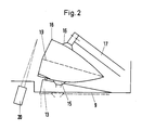
- Fig. 2 eine schematische Schnittdarstellung quer zur Transportebene durch die wesentlichen Teile der Vorrichtung nach Fig. l;
- Fig. 3 eine schematische Ansicht aus der Sicht der Bedienungsperson einschließlich einer darunterliegenden Draufsicht;
- Fig. 4 eine schematische Ansicht aus der Sicht der Bedienungsperson mit senkrecht zur Umschlagebene bewegten Saugern;
- Fig. 5 eine der Fig. 4 entsprechende Ansicht, jedoch mit zusätzlich in der Umschlagebene durch eine Kippbewegung bewegten oberen Sauger; und
- Fig. 6 eine der Fig. 5 entsprechende Ansicht, jedoch mit einem zusätzlichen Vorsprung angrenzend an den unteren Sauger zur Erzeugung einer weiteren Verwerfung der unteren Umschlagseite.
- Die in der Zeichnung, insbesondere in Fig. l, dargestellte Vorrichtung zeigt ein Entnahmegerät l und ein Untertischaggregat 2, in dem der Starkstromteil und die Vakuumpumpe untergebracht sind. Durch die Trennung des Untertischaggregates von dem Entnahmegerät kann das Entnahmegerät auch an einem anderen Ort als das Untertischaggregat eingesetzt werden. Ein Arbeitstisch 3 trägt das Entnahmegerät und eine Umschlagablage. Weiterhin ist ein Sortierfach strichpunktiert angedeutet.
- Der Standpunkt 6 für die Bedienungsperson befindet sich vor einer mit 5 bezeichneten Entnahmefläche. Die zu öffnenden Briefumschläge l8 werden in einem Ablageschacht 7 angeordnet. Aus dem Ablageschacht 7 werden sie durch einen Sauger an einem Saugarm 8 entnommen. Die Steuerung erfolgt durch eine Fotozelle 20.
- An diesen Teil schließt sich in Bearbeitungsrichtung die im wesentlichen waagerecht liegende Transportebene mit einem Fördersystem an. Das Schneidwerk ist mit l0 bezeichnet. Die Schneidwerkzeuge sind durch eine Verstellung 29 verstellbar. Auf der Transportebene 9 gelangen die Umschläge nach dem Aufschneiden an der vorderen Umschlagkante in der durch den Pfeil in Fig. l angedeuteten Transporteinrichtung in die eigentliche Entnahmestation l2.
- Die Entnahmestation wird durch zwei Sauger l5 und l6 gebildet. Der untere Sauger l5, der in der Transportebene 9 liegt, ist an einem schwenkbaren Tischsegment l3 befestigt.
- Der obere Sauger l6 ist an einem Saugarm l7 befestigt.
- Der Fig. l ist zu entnehmen, daß die Transportebene 9 etwas tiefer liegt als die Entnahmefläche 5, so daß eine Umschlagführungskante ll entsteht.
- Für die in Transportrichtung vorne liegende Umschlagkante 28 sind für verschiedene Umschlaggrößen Anschläge l4 vorgesehen.
- Eine Fotozelle 20 erfaßt die Entnahme des Umschlaginhaltes l9 und löst dadurch den nächsten Entnahmetakt bzw. Maschinentakt aus.
- Dem oberen Sauger l6 liegt ein Kontaktschalter 24 gegenüber. Dem unteren Sauger l5 liegt ein Gegenhalter 25 gegenüber, da die beiden Sauger l5 und l6 in der Umschlagebene gegeneinander versetzt sind.
- An dem Tischsegment l3 ist ein Vorsprung 26 angrenzend an den unteren Sauger l5 vorgesehen.
- Das Tischsegment ist um die Längskante schwenkbar, die parallel zu der Umschlagführungskante ll aber von dieser entfernt liegt. Die vordere Kante des Tischsegmentes wird ungefähr auf die Höhe der Entnahmefläche 5 geschwenkt.
- Im Betrieb werden die mit Hilfe des Saugarmes 8 vereinzelten und durch das Schneidwerk l0 an der Vorderkante geöffneten Briefumschläge l8 durch die Fördereinrichtung in der Transportebene 9 in die Entnahmestation l2 gefördert und zwar bis zum Erreichen des entsprechenden Anschlages l4.l oder l4.2. Diese Stellung ist in Fig. 3 gut erkennbar. Die Fotozelle 22 stellt die Länge des entsprechenden Briefumschlages fest und steuert die Anschläge l4.l oder l4.2.. Der Saugarm l7 mit dem oberen Sauger l6 wird nach Eintreffen des Briefumschlages in die Entnahmestation nach unten auf den Umschlag bewegt. Die entsprechende Endstellung des oberen Saugers l6 wird durch den Kontaktschalter 24 ermittelt, der das Anlegen des Vakuums und die weiteren Bewegungen steuert. Nach dem Anlegen des Vakuums werden das Tischsegment l3 mit dem unteren Sauger und der Saugarm l7 mit dem oberen Sauger l6 gemeinsam hochgeschwenkt, bis die Stellung erreicht ist, die für ein Einsehen der Bedienungsperson in den Umschlag angestrebt wird. Der Saugarm l7 mit dem oberen Sauger l6 setzt seine Bewegung senkrecht zur Umschlagebene fort, um den Umschlag so zu öffnen, wie es in Fig. 4 dargestellt ist. Parallel hierzu führt der Saugarm l7 mit dem oberen Sauger l6 die Bewegung in der Umschlagebene durch, wie es in Fig. 5 dargestellt ist. Diese Bewegung ist eine Kippbewegung um den Kippwinkel 23.
- Bei dieser Ausführungsform ist auf dem Tischsegment l3 ein Vorsprung 26 vorgesehen, der angrenzend an den Sauger l5 vorgesehen ist und in diesem Bereich für eine weitere Verwerfung und damit sichere Trennung von Umschlag und Inhalt sorgt.
- Der Bewegungsablauf der Sauger und ihre Wirkung auf den Umschlag l8 und den Inhalt l9 lassen sich deutlich aus den Fig. 4 bis 5 entnehmen. Durch die besondere Schwenkbewegung des oberen Saugers l6 wird die Umschlagkante 28 hochgezogen und dabei der gegebenenfalls mit angesaugte Inhalt von dem Umschlag getrennt. Der Vorsprung 26 unterstützt diese Trennung.
- Die Entleerung des Umschlages wird durch die Fotozelle 20 erfaßt, so daß der nächste Entnahmetakt ausgelöst werden kann. Hierdurch bestimmt die Bedienungsperson die Entnahmegeschwindigkeit selbst.
- Anstelle der Verwendung mehrerer Anschläge l4.l und l4.2 ist es auch möglich, lediglich einen Anschlag l4 vorzusehen, der entsprechend verstellt werden kann.
- Bei einer nicht dargestellten anderen Ausführungsform ist der untere Sauger l5 nicht mit dem Tischsegment l3 fest verbunden, sondern getrennt von diesem senkrecht zur Umschlagebene bewegbar. In diesem Falle ist der Sauger l5 an einem eigenen Saugarm befestigt.
-
- l Entnahmegerät
- 2 Untertischaggregat
- 3 Arbeitstisch
- 4 Umschlagablage
- 5 Entnahmefläche
- 6 Bedienungsperson
- 7 Ablageschacht
- 8 Saugarm
- 9 Transportebene
- l0 Schneidwerk
- ll Umschlagführungskasten
- l2 Entnahmestation
- l3 Tischsegment
- l4 Anschlag
- l5 unterer Sauger
- l6 oberer Sauger
- l7 Saugarm
- l8 Briefumschlag
- l9 Umschlaginhalt
- 20 Fotozelle
- 2l Umschlagstapel
- 22 Fotozelle
- 23 Schwenkwinkel
- 24 Kontaktschalter
- 25 Gegenhalter
- 26 Vorsprung
- 27 Wellenform
- 28 Umschlagkante
- 29 Verstellung
Claims (10)
und daß das Tischsegment (l3) bzw. dessen Vorderkante angrenzend an die Umschlagführungskante (ll) auf die Ebene der Entnahmefläche (5) hochschwenkbar ist.
Priority Applications (4)
| Application Number | Priority Date | Filing Date | Title |
|---|---|---|---|
| AT87102460T ATE52461T1 (de) | 1987-02-21 | 1987-02-21 | Vorrichtung zum entleeren von briefumschlaegen. |
| EP87102460A EP0279870B1 (de) | 1987-02-21 | 1987-02-21 | Vorrichtung zum Entleeren von Briefumschlägen |
| DE8787102460T DE3762594D1 (de) | 1987-02-21 | 1987-02-21 | Vorrichtung zum entleeren von briefumschlaegen. |
| US07/150,381 US4866908A (en) | 1987-02-21 | 1988-01-29 | Table-top mail extraction apparatus having separate, connectable power unit |
Applications Claiming Priority (1)
| Application Number | Priority Date | Filing Date | Title |
|---|---|---|---|
| EP87102460A EP0279870B1 (de) | 1987-02-21 | 1987-02-21 | Vorrichtung zum Entleeren von Briefumschlägen |
Publications (2)
| Publication Number | Publication Date |
|---|---|
| EP0279870A1 true EP0279870A1 (de) | 1988-08-31 |
| EP0279870B1 EP0279870B1 (de) | 1990-05-09 |
Family
ID=8196772
Family Applications (1)
| Application Number | Title | Priority Date | Filing Date |
|---|---|---|---|
| EP87102460A Expired - Lifetime EP0279870B1 (de) | 1987-02-21 | 1987-02-21 | Vorrichtung zum Entleeren von Briefumschlägen |
Country Status (4)
| Country | Link |
|---|---|
| US (1) | US4866908A (de) |
| EP (1) | EP0279870B1 (de) |
| AT (1) | ATE52461T1 (de) |
| DE (1) | DE3762594D1 (de) |
Cited By (3)
| Publication number | Priority date | Publication date | Assignee | Title |
|---|---|---|---|---|
| US5440861A (en) * | 1992-04-09 | 1995-08-15 | Stielow Gmbh & Co. Kg | Method and apparatus for emptying envelopes |
| US5813668A (en) * | 1994-03-31 | 1998-09-29 | Stielow Gmbh & Co. | Apparatus for conveying and staggering envelope contents for review by an operator |
| US20150314903A1 (en) * | 2014-05-02 | 2015-11-05 | Fujifilm Corporation | Automatic taking-out method and device for packaged contents |
Families Citing this family (12)
| Publication number | Priority date | Publication date | Assignee | Title |
|---|---|---|---|---|
| JP2983992B2 (ja) * | 1988-09-01 | 1999-11-29 | 日本テトラパック株式会社 | 包装容器用ブランクの移送装置 |
| US4962624A (en) * | 1989-12-20 | 1990-10-16 | Pitney Bowes Inc. | Envelope opening apparatus |
| US5374152A (en) * | 1992-08-03 | 1994-12-20 | Agissar Corporation | Automatic content separating system |
| US5598686A (en) * | 1995-11-13 | 1997-02-04 | Owen Tri-Cut Limited | Mail processing equipment |
| DE10015756C2 (de) * | 2000-03-29 | 2003-06-12 | Pitney Bowes Technologies Gmbh | Kuvertierstation |
| DE50100264D1 (de) * | 2001-08-16 | 2003-06-26 | Stielow Gmbh | Vorrichtung zum Vereinzeln von Breifumschlägen |
| US7992853B2 (en) * | 2003-06-07 | 2011-08-09 | Opex Corporation | Method and apparatus for processing mail to obtain image data of contents |
| US7537203B2 (en) * | 2003-06-07 | 2009-05-26 | Opex Corporation | Method and apparatus for processing mail obtain image data of contents |
| US8157254B2 (en) * | 2004-06-04 | 2012-04-17 | Opex Corporation | Method and apparatus for processing mail to obtain image data of contents |
| USD574881S1 (en) * | 2005-03-07 | 2008-08-12 | Opex Corporation | Document processing device |
| US7866936B2 (en) * | 2007-05-01 | 2011-01-11 | Northrop Grumman Systems Corporation | System and method for transferring mail between containers |
| BR112012026761A2 (pt) | 2010-04-19 | 2017-10-10 | Opex Corp | aparelho para processamento de documentos, e, método para processamento de documentos |
Citations (4)
| Publication number | Priority date | Publication date | Assignee | Title |
|---|---|---|---|---|
| CH267710A (de) * | 1945-02-20 | 1950-04-15 | Uni Fold Machinery Company Lim | Verfahren und Vorrichtung zum serienweisen Einsetzen von Schriftstücken in Umschläge. |
| US4271656A (en) * | 1979-09-26 | 1981-06-09 | Mail-Ex Corporation | Envelope processing machine |
| EP0036941A1 (de) * | 1980-04-02 | 1981-10-07 | Stielow GmbH | Vorrichtung zum Entleeren von Briefumschlägen |
| EP0041314A1 (de) * | 1980-05-30 | 1981-12-09 | Mail-Ex Corporation | Verfahren und Vorrichtung zum Behandeln von Briefumschlägen |
Family Cites Families (15)
| Publication number | Priority date | Publication date | Assignee | Title |
|---|---|---|---|---|
| US32328A (en) * | 1861-05-14 | Field-bucket | ||
| DE1006310B (de) * | 1953-11-26 | 1957-04-11 | Gustav Schickedanz | Briefoeffnungsmaschine |
| DE963126C (de) * | 1955-11-10 | 1957-05-02 | Gustav Schickedanz Fa | Verfahren und Vorrichtung zum OEffnen von Briefen |
| US3384252A (en) * | 1966-11-22 | 1968-05-21 | Horace M. West | Apparatus for extracting items from envelopes |
| US3691726A (en) * | 1970-11-05 | 1972-09-19 | Stephens Ind Inc | Method and apparatus for opening envelopes |
| US4016708A (en) * | 1974-08-13 | 1977-04-12 | Docutronix, Inc. | Envelope processing machine |
| US3979884A (en) * | 1974-09-30 | 1976-09-14 | Opex Corporation | Mail extracting and sorting desk |
| USRE32328E (en) | 1974-09-30 | 1987-01-13 | Opex Corporation | Mail extracting and sorting desk |
| CH583609A5 (de) * | 1974-11-05 | 1977-01-14 | Aluminiumwerke Ag Rorschach | |
| US4050222A (en) * | 1975-08-29 | 1977-09-27 | Stephens Industries, Inc. | Envelope opening apparatus |
| US4159611A (en) * | 1976-07-22 | 1979-07-03 | Mail-Ex Corporation | Envelope processing machine and method |
| US4318322A (en) * | 1976-07-22 | 1982-03-09 | Mail-Ex Corporation | Envelope cutter apparatus |
| US4110958A (en) * | 1977-04-11 | 1978-09-05 | Stevens Albert F | Extraction of contents from envelopes |
| US4124968A (en) * | 1977-07-08 | 1978-11-14 | Opex Corporation | Content activated envelope extraction |
| US4353197A (en) * | 1977-07-08 | 1982-10-12 | Opex Corporation | Content activated envelope extraction |
-
1987
- 1987-02-21 DE DE8787102460T patent/DE3762594D1/de not_active Expired - Fee Related
- 1987-02-21 EP EP87102460A patent/EP0279870B1/de not_active Expired - Lifetime
- 1987-02-21 AT AT87102460T patent/ATE52461T1/de not_active IP Right Cessation
-
1988
- 1988-01-29 US US07/150,381 patent/US4866908A/en not_active Expired - Fee Related
Patent Citations (4)
| Publication number | Priority date | Publication date | Assignee | Title |
|---|---|---|---|---|
| CH267710A (de) * | 1945-02-20 | 1950-04-15 | Uni Fold Machinery Company Lim | Verfahren und Vorrichtung zum serienweisen Einsetzen von Schriftstücken in Umschläge. |
| US4271656A (en) * | 1979-09-26 | 1981-06-09 | Mail-Ex Corporation | Envelope processing machine |
| EP0036941A1 (de) * | 1980-04-02 | 1981-10-07 | Stielow GmbH | Vorrichtung zum Entleeren von Briefumschlägen |
| EP0041314A1 (de) * | 1980-05-30 | 1981-12-09 | Mail-Ex Corporation | Verfahren und Vorrichtung zum Behandeln von Briefumschlägen |
Cited By (5)
| Publication number | Priority date | Publication date | Assignee | Title |
|---|---|---|---|---|
| US5440861A (en) * | 1992-04-09 | 1995-08-15 | Stielow Gmbh & Co. Kg | Method and apparatus for emptying envelopes |
| US5813668A (en) * | 1994-03-31 | 1998-09-29 | Stielow Gmbh & Co. | Apparatus for conveying and staggering envelope contents for review by an operator |
| US20150314903A1 (en) * | 2014-05-02 | 2015-11-05 | Fujifilm Corporation | Automatic taking-out method and device for packaged contents |
| US9902520B2 (en) * | 2014-05-02 | 2018-02-27 | Fujifilm Corporation | Automatic taking-out method and device for packaged contents |
| US10023343B2 (en) | 2014-05-02 | 2018-07-17 | Fujifilm Corporation | Automatic taking-out method and device for packaged contents |
Also Published As
| Publication number | Publication date |
|---|---|
| US4866908A (en) | 1989-09-19 |
| ATE52461T1 (de) | 1990-05-15 |
| EP0279870B1 (de) | 1990-05-09 |
| DE3762594D1 (de) | 1990-06-13 |
Similar Documents
| Publication | Publication Date | Title |
|---|---|---|
| EP0279870A1 (de) | Vorrichtung zum Entleeren von Briefumschlägen | |
| EP0056874B2 (de) | Vorrichtung zum Schneiden von Papier, Pappe oder dgl | |
| DE2543692A1 (de) | Vorrichtung zum erleichtern des herausnehmens des inhaltes von umschlaegen und zum sortieren des umschlaginhaltes | |
| DE2657694C3 (de) | Spulenwechselvorrichtung an einer Offenendspinnmaschine | |
| DE19710236A1 (de) | Vorrichtung zum Bearbeiten von flachen, flexiblen Gegenständen, wie z. B. Karten aus Kunststoff oder Papier | |
| DE102004016372A1 (de) | Vorrichtung zum Bewegen von Buchblöcken in einer Vorrichtung zum Beschneiden von Buchblöcken | |
| EP0036941B1 (de) | Vorrichtung zum Entleeren von Briefumschlägen | |
| DE3233747C1 (de) | Vorrichtung zum Koepfen gekehlten Fischs | |
| EP0620174A1 (de) | Vorrichtung zum Vereinzeln von Bogen eines Bogenstapels | |
| EP0565837B1 (de) | Verfahren und Vorrichtung zum Entleeren von Briefumschlägen | |
| EP0080185B1 (de) | Verfahren und Einrichtung zum Öffnen von zwei- oder mehrblättrigen Erzeugnissen, insbesondere Druckprodukten | |
| EP1249408A1 (de) | Vorrichtung zum Ergreifen, Transportieren und/oder Positionieren von Stapeln aus blattartigen Materialien | |
| DE69104123T2 (de) | Verfahren und Vorrichtung zum Entleeren von Briefen. | |
| EP0202503A2 (de) | Vorrichtung zum Trennen von gefalteten und perforierten Endlos-Papieren | |
| EP1149791B1 (de) | Vorrichtung zur Probebogenentnahme an einem Ausleger einer Bogendruckmaschine | |
| DE2535889C2 (de) | Maschine zum Entleeren eines insgesamt rechteckigen Briefumschlags | |
| CH664749A5 (de) | Verfahren und vorrichtung zum sammeln einer anzahl blaetter aus einer reihe von stapeln. | |
| EP0262442A2 (de) | Vorrichtung zum Sortieren und Transportieren von Blechzuschnitten | |
| DE102010017416B4 (de) | Vorrichtung zum Sortieren von Gebinden | |
| DE9309930U1 (de) | Vereinzelungs- und Transportvorrichtung für blattförmige Werkstücke | |
| DE3729121C2 (de) | ||
| EP0452708B1 (de) | Bogenausscheidevorrichtung | |
| DE9013640U1 (de) | Vorschubvorrichtung zum Zuführen von Werkstückplatten in Plattensägen | |
| DE506050C (de) | Vorrichtung zum Einstecken oder Zusammentragen von Zeitungen | |
| DE2153051A1 (de) | Verfahren und vorrichtung zum ausrichten von briefen od.dgl. auf ihrem transportweg von einer aufgabestelle zu einer selbsttaetig arbeitenden sortiervorrichtung |
Legal Events
| Date | Code | Title | Description |
|---|---|---|---|
| PUAI | Public reference made under article 153(3) epc to a published international application that has entered the european phase |
Free format text: ORIGINAL CODE: 0009012 |
|
| 17P | Request for examination filed |
Effective date: 19880422 |
|
| AK | Designated contracting states |
Kind code of ref document: A1 Designated state(s): AT BE CH DE ES FR GB IT LI NL SE |
|
| 17Q | First examination report despatched |
Effective date: 19890111 |
|
| GRAA | (expected) grant |
Free format text: ORIGINAL CODE: 0009210 |
|
| AK | Designated contracting states |
Kind code of ref document: B1 Designated state(s): AT BE CH DE ES FR GB IT LI NL SE |
|
| PG25 | Lapsed in a contracting state [announced via postgrant information from national office to epo] |
Ref country code: NL Effective date: 19900509 Ref country code: SE Effective date: 19900509 Ref country code: BE Effective date: 19900509 Ref country code: IT Free format text: LAPSE BECAUSE OF FAILURE TO SUBMIT A TRANSLATION OF THE DESCRIPTION OR TO PAY THE FEE WITHIN THE PRE;WARNING: LAPSES OF ITALIAN PATENTS WITH EFFECTIVE DATE BEFORE 2007 MAY HAVE OCCURRED AT ANY TIME BEFORE 2007. THE CORRECT EFFECTIVE DATE MAY BE DIFFERENT FROM THE ONE RECORDED.SCRIBED TIME-LIMIT Effective date: 19900509 |
|
| REF | Corresponds to: |
Ref document number: 52461 Country of ref document: AT Date of ref document: 19900515 Kind code of ref document: T |
|
| REF | Corresponds to: |
Ref document number: 3762594 Country of ref document: DE Date of ref document: 19900613 |
|
| GBT | Gb: translation of ep patent filed (gb section 77(6)(a)/1977) | ||
| ET | Fr: translation filed | ||
| PG25 | Lapsed in a contracting state [announced via postgrant information from national office to epo] |
Ref country code: ES Free format text: LAPSE BECAUSE OF FAILURE TO SUBMIT A TRANSLATION OF THE DESCRIPTION OR TO PAY THE FEE WITHIN THE PRESCRIBED TIME-LIMIT Effective date: 19900820 |
|
| NLV1 | Nl: lapsed or annulled due to failure to fulfill the requirements of art. 29p and 29m of the patents act | ||
| PG25 | Lapsed in a contracting state [announced via postgrant information from national office to epo] |
Ref country code: AT Effective date: 19910221 |
|
| PG25 | Lapsed in a contracting state [announced via postgrant information from national office to epo] |
Ref country code: CH Effective date: 19910228 Ref country code: LI Effective date: 19910228 |
|
| PLBE | No opposition filed within time limit |
Free format text: ORIGINAL CODE: 0009261 |
|
| STAA | Information on the status of an ep patent application or granted ep patent |
Free format text: STATUS: NO OPPOSITION FILED WITHIN TIME LIMIT |
|
| 26N | No opposition filed | ||
| REG | Reference to a national code |
Ref country code: CH Ref legal event code: PL |
|
| PGFP | Annual fee paid to national office [announced via postgrant information from national office to epo] |
Ref country code: DE Payment date: 19920123 Year of fee payment: 6 |
|
| PGFP | Annual fee paid to national office [announced via postgrant information from national office to epo] |
Ref country code: GB Payment date: 19920205 Year of fee payment: 6 |
|
| PGFP | Annual fee paid to national office [announced via postgrant information from national office to epo] |
Ref country code: FR Payment date: 19920214 Year of fee payment: 6 |
|
| PG25 | Lapsed in a contracting state [announced via postgrant information from national office to epo] |
Ref country code: GB Effective date: 19930221 |
|
| GBPC | Gb: european patent ceased through non-payment of renewal fee |
Effective date: 19930221 |
|
| PG25 | Lapsed in a contracting state [announced via postgrant information from national office to epo] |
Ref country code: FR Effective date: 19931029 |
|
| PG25 | Lapsed in a contracting state [announced via postgrant information from national office to epo] |
Ref country code: DE Effective date: 19931103 |
|
| REG | Reference to a national code |
Ref country code: FR Ref legal event code: ST |