EP0265628B1 - Abschneidevorrichtung für plastische Stränge - Google Patents
Abschneidevorrichtung für plastische Stränge Download PDFInfo
- Publication number
- EP0265628B1 EP0265628B1 EP87112620A EP87112620A EP0265628B1 EP 0265628 B1 EP0265628 B1 EP 0265628B1 EP 87112620 A EP87112620 A EP 87112620A EP 87112620 A EP87112620 A EP 87112620A EP 0265628 B1 EP0265628 B1 EP 0265628B1
- Authority
- EP
- European Patent Office
- Prior art keywords
- cutting
- wire
- guiding element
- column
- cutting wire
- Prior art date
- Legal status (The legal status is an assumption and is not a legal conclusion. Google has not performed a legal analysis and makes no representation as to the accuracy of the status listed.)
- Expired
Links
- 238000005520 cutting process Methods 0.000 title claims abstract description 61
- 239000003000 extruded plastic Substances 0.000 title 1
- 238000004140 cleaning Methods 0.000 claims abstract description 6
- 239000000463 material Substances 0.000 claims description 4
- 230000000284 resting effect Effects 0.000 claims 1
- 239000003054 catalyst Substances 0.000 abstract description 2
- 230000003197 catalytic effect Effects 0.000 abstract 1
- 239000000919 ceramic Substances 0.000 abstract 1
- 238000000034 method Methods 0.000 abstract 1
- 230000000737 periodic effect Effects 0.000 abstract 1
- 230000006835 compression Effects 0.000 description 1
- 238000007906 compression Methods 0.000 description 1
- 238000010276 construction Methods 0.000 description 1
- 238000004519 manufacturing process Methods 0.000 description 1
- 238000000465 moulding Methods 0.000 description 1
Images

Classifications
-
- B—PERFORMING OPERATIONS; TRANSPORTING
- B26—HAND CUTTING TOOLS; CUTTING; SEVERING
- B26D—CUTTING; DETAILS COMMON TO MACHINES FOR PERFORATING, PUNCHING, CUTTING-OUT, STAMPING-OUT OR SEVERING
- B26D1/00—Cutting through work characterised by the nature or movement of the cutting member or particular materials not otherwise provided for; Apparatus or machines therefor; Cutting members therefor
- B26D1/01—Cutting through work characterised by the nature or movement of the cutting member or particular materials not otherwise provided for; Apparatus or machines therefor; Cutting members therefor involving a cutting member which does not travel with the work
- B26D1/547—Cutting through work characterised by the nature or movement of the cutting member or particular materials not otherwise provided for; Apparatus or machines therefor; Cutting members therefor involving a cutting member which does not travel with the work having a wire-like cutting member
-
- B—PERFORMING OPERATIONS; TRANSPORTING
- B28—WORKING CEMENT, CLAY, OR STONE
- B28B—SHAPING CLAY OR OTHER CERAMIC COMPOSITIONS; SHAPING SLAG; SHAPING MIXTURES CONTAINING CEMENTITIOUS MATERIAL, e.g. PLASTER
- B28B11/00—Apparatus or processes for treating or working the shaped or preshaped articles
- B28B11/14—Apparatus or processes for treating or working the shaped or preshaped articles for dividing shaped articles by cutting
- B28B11/16—Apparatus or processes for treating or working the shaped or preshaped articles for dividing shaped articles by cutting for extrusion or for materials supplied in long webs
-
- B—PERFORMING OPERATIONS; TRANSPORTING
- B29—WORKING OF PLASTICS; WORKING OF SUBSTANCES IN A PLASTIC STATE IN GENERAL
- B29C—SHAPING OR JOINING OF PLASTICS; SHAPING OF MATERIAL IN A PLASTIC STATE, NOT OTHERWISE PROVIDED FOR; AFTER-TREATMENT OF THE SHAPED PRODUCTS, e.g. REPAIRING
- B29C48/00—Extrusion moulding, i.e. expressing the moulding material through a die or nozzle which imparts the desired form; Apparatus therefor
- B29C48/001—Combinations of extrusion moulding with other shaping operations
- B29C48/0022—Combinations of extrusion moulding with other shaping operations combined with cutting
-
- B—PERFORMING OPERATIONS; TRANSPORTING
- B29—WORKING OF PLASTICS; WORKING OF SUBSTANCES IN A PLASTIC STATE IN GENERAL
- B29C—SHAPING OR JOINING OF PLASTICS; SHAPING OF MATERIAL IN A PLASTIC STATE, NOT OTHERWISE PROVIDED FOR; AFTER-TREATMENT OF THE SHAPED PRODUCTS, e.g. REPAIRING
- B29C48/00—Extrusion moulding, i.e. expressing the moulding material through a die or nozzle which imparts the desired form; Apparatus therefor
- B29C48/03—Extrusion moulding, i.e. expressing the moulding material through a die or nozzle which imparts the desired form; Apparatus therefor characterised by the shape of the extruded material at extrusion
- B29C48/05—Filamentary, e.g. strands
-
- B—PERFORMING OPERATIONS; TRANSPORTING
- B29—WORKING OF PLASTICS; WORKING OF SUBSTANCES IN A PLASTIC STATE IN GENERAL
- B29C—SHAPING OR JOINING OF PLASTICS; SHAPING OF MATERIAL IN A PLASTIC STATE, NOT OTHERWISE PROVIDED FOR; AFTER-TREATMENT OF THE SHAPED PRODUCTS, e.g. REPAIRING
- B29C2793/00—Shaping techniques involving a cutting or machining operation
- B29C2793/0027—Cutting off
-
- B—PERFORMING OPERATIONS; TRANSPORTING
- B29—WORKING OF PLASTICS; WORKING OF SUBSTANCES IN A PLASTIC STATE IN GENERAL
- B29C—SHAPING OR JOINING OF PLASTICS; SHAPING OF MATERIAL IN A PLASTIC STATE, NOT OTHERWISE PROVIDED FOR; AFTER-TREATMENT OF THE SHAPED PRODUCTS, e.g. REPAIRING
- B29C48/00—Extrusion moulding, i.e. expressing the moulding material through a die or nozzle which imparts the desired form; Apparatus therefor
- B29C48/03—Extrusion moulding, i.e. expressing the moulding material through a die or nozzle which imparts the desired form; Apparatus therefor characterised by the shape of the extruded material at extrusion
- B29C48/12—Articles with an irregular circumference when viewed in cross-section, e.g. window profiles
-
- Y—GENERAL TAGGING OF NEW TECHNOLOGICAL DEVELOPMENTS; GENERAL TAGGING OF CROSS-SECTIONAL TECHNOLOGIES SPANNING OVER SEVERAL SECTIONS OF THE IPC; TECHNICAL SUBJECTS COVERED BY FORMER USPC CROSS-REFERENCE ART COLLECTIONS [XRACs] AND DIGESTS
- Y10—TECHNICAL SUBJECTS COVERED BY FORMER USPC
- Y10T—TECHNICAL SUBJECTS COVERED BY FORMER US CLASSIFICATION
- Y10T83/00—Cutting
- Y10T83/04—Processes
-
- Y—GENERAL TAGGING OF NEW TECHNOLOGICAL DEVELOPMENTS; GENERAL TAGGING OF CROSS-SECTIONAL TECHNOLOGIES SPANNING OVER SEVERAL SECTIONS OF THE IPC; TECHNICAL SUBJECTS COVERED BY FORMER USPC CROSS-REFERENCE ART COLLECTIONS [XRACs] AND DIGESTS
- Y10—TECHNICAL SUBJECTS COVERED BY FORMER USPC
- Y10T—TECHNICAL SUBJECTS COVERED BY FORMER US CLASSIFICATION
- Y10T83/00—Cutting
- Y10T83/929—Tool or tool with support
- Y10T83/9292—Wire tool
Definitions
- the invention relates to a cutting device for plastic strands according to the preamble of claim 1.
- the most common cutters either share the strand with horizontally stretched wires that are passed vertically through the strand or with vertically stretched wires that are passed horizontally.
- a cutting device of the type mentioned in which the cutting wires are arranged in a star shape between an annular wire guide body and its axis of rotation.
- the wire guide body encloses the strand, the support for the strand being arranged laterally next to the axis of rotation.
- circular guides are provided eccentrically to the axis of rotation, which likewise surround the strand. Links run around the guides with wiping lips, which are moved back and forth along the cutting wires to keep them clean.
- the cutting wire executes an entirely or almost entirely vertical movement path at the contact point against the cutting surface. This results in a vertical pressure at the interface, which leads to compression of the plastic material and faster wear of the cutting wires.
- this device has considerable dimensions. This is because the diameter of the annular wire guide body is disproportionately large, because on the one hand the attachment of the wires to the axis of rotation requires sufficient free space for the passage of the strand, and on the other hand the annular wire guide body must enclose the circular guides for the cleaning members.
- the invention has for its object to provide a cutting device of the type mentioned, in which the vertical pressure of the cutting wire is reduced and at the same time the dimensions of the device can be kept as small as possible.
- An advantage of the device according to the invention is that the path of movement of the cutting wire always has a vertical component and a component running in the longitudinal direction of the wire, so that the cutting wire makes a saw-like cutting movement.
- the saw-like cutting prevents the material from being pressed at the interface and at the same time, the cutting wire is less stressed.
- Another advantage is the fact that the strand can pass centrally through the annular wire guide body, so that its diameter only has to be matched to the cross section of the strand.
- the claim 3 represents a very simple execution of the saw-like cutting movement of the cutting wire again.
- the claim 6 contains a measure that allows the cutting wire to be kept clean with the least possible construction effort.
- the cutting device 2 is mounted on a carriage (not shown), which can either be moved synchronously with it or can stand still to cut the strand 1, and is equipped with an annular wire guide body 3, the rotation of which is carried out by an external drive.
- the strand 1 or a strand piece runs through the wire guide body 3 approximately in the middle thereof and is transported on a slotted cutting table 4.
- the cutting wire 5 is on the one hand attached to a wire fastening 10 on the annular wire guide body 3 and, on the other hand, is mounted on a fixed guide body 6, which is arranged outside the annular wire guide body 3 and aligned with the center of the strand height.
- the fixed guide body 6 has a coil 7, onto or from which the cutting wire can be wound or unwound and is held under uniform tension.
- a plurality of cutting planes A, each with a cutting wire 5, can also be provided in parallel for the simultaneous severing of a plurality of moldings, for which purpose a corresponding number of coils must then be provided on the two guide bodies.
- a simplified embodiment for the saw-like cutting movement is shown, in which the wire on the fixed guide body 6 is guided over a deflection roller 7a and held by a weight 8 under constant tension.
- a guide and cleaning bar for the wire 5 is articulated on the fixed guide body 6.
- the wire is articulated on the wire fastening 10 of the annular wire guide body 3.
Landscapes
- Engineering & Computer Science (AREA)
- Mechanical Engineering (AREA)
- Life Sciences & Earth Sciences (AREA)
- Forests & Forestry (AREA)
- Structural Engineering (AREA)
- Chemical & Material Sciences (AREA)
- Ceramic Engineering (AREA)
- Processing Of Stones Or Stones Resemblance Materials (AREA)
- Finish Polishing, Edge Sharpening, And Grinding By Specific Grinding Devices (AREA)
- Devices For Post-Treatments, Processing, Supply, Discharge, And Other Processes (AREA)
Description
- Die Erfindung betrifft eine Abschneidevorrichtung für plastische Stränge gemäß dem Oberbegriff des Anspruches 1.
- Bei plastischen Strängen, insbesondere bei solchen für die Herstellung von Katalysatoren, ist es wesentlich, den Schneidedraht so zu führen, daß möglichst saubere Schnittkanten entstehen und die Stege nicht zerdrückt werden. Ferner müssen verschlissene Drähte erneuerbar sein.
- Die gebräuchlichsten Abschneidevorrichtungen teilen den Strang entweder mit horizontal gespannten Drähten, die vertikal durch den Strang geführt werden, oder mit vertikal gespannten Drähten, die horizontal geführt werden.
- Aus der DE-AS 2 100 819 ist eine Abschneidevorrichtung der eingangs genannten Art bekannt, bei der die Schneidedrähte sternförmig zwischen einem kreisringförmigen Drahtführungskörper und dessen Drehachse angeordnet sind. Der Drahtführungskörper umschließt den Strang, wobei die Auflage für den Strang seitlich neben der Drehachse angeordnet ist. Zur Reinigung der Schneidedrähte sind exzentrisch zur Drehachse kreisförmige Führungen vorgesehen, die ebenfalls den Strang umgeben. In den Führungen laufen Glieder mit Abstreiflippen um, die entlang den Schneidedrähten hin- und herbewegt werden, um diese sauber zu halten.
- Auch bei dieser Abschneidevorrichtung führt der Schneidedraht an der Kontaktstelle eine gänzlich bzw. nahezu gänzlich vertikale Bewegungsbahn gegen die Schnittfläche aus. Dies ergibt an der Schnittstelle einen vertikalen Druck, der zur Verdrückung des plastischen Materials und zu einem rascheren Verschleiß der Schneidedrähte führt.
- Ferner hat diese Vorrichtung erhebliche Ausmaße. Dies liegt daran, daß der Durchmesser des kreisringförmigen Drahtführungskörpers unverhältnismäßig groß ist, weil zum einen die Befestigung der Drähte an der Drehachse ausreichend freien Platz für den Durchgang des Stranges erfordert, zum anderen der kreisringförmige Drahtführungskörper die Kreisführungen für die Reinigungsglieder umschließen muß.
- Der Erfindung liegt die Aufgabe zugrunde, eine Abschneidevorrichtung der eingangs genannten Art zu schaffen, bei der der vertikale Druck des Schneidedrahtes vermindert und zugleich die Abmessungen der Vorrichtung möglichst klein gehalten werden können.
- Diese Aufgabe wird durch die im kennzeichnendenTeil des Anspruchs 1 angegebene Ausbildung gelöst.
- Ein Vorteil der Vorrichtung nach der Erfindung besteht darin, daß die Bewegungsbahn des Schneidedrahtes stets eine vertikale und eine in Längsrichtung des Drahtes verlaufende Komponente hat, so daß der Schneidedraht eine sägeartige Schnittbewegung macht. Durch das sägeartige Schneiden wird ein Verdrücken des Materials an der Schnittstelle vermieden u. zugleich der Schneidedraht weniger beansprucht.
- Ein weiterer Vorteil ist darin zu sehen, daß der Strang zentral den kreisringförmigen Drahtführungskörper durchlaufen kann, so daß dessen Durchmesser nur auf den Querschnitt des Stranges abgestimmt werden muß.
- Weitere Merkmale der Erfindung sind den Ansprüchen 2 bis 7 zu entnehmen.
- Mit der Ausbildung gemäß dem Anspruch 2 wird erreicht, daß der Draht im Schnittbereich kontinuierlich erneuert wird, also ein sofortiges Auswechseln des ganzen Drahtes bei Auftreten von Verschleißstellen entfällt.
- Der Anspruch 3 gibt eine denkbar einfache Ausführung der sägeartigen Schnittbewegung des Schneidedrahtes wieder.
- Der Anspruch 6 enthält eine Maßnahme, die das ständige Sauberhalten des Schneidedrahtes mit geringst möglichem baulichen Aufwand erlaubt.
- Ausführungsbeispiele der Erfindung sind in der Zeichnung dargestellt und im folgenden näher beschrieben. Es zeigen:
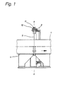
- Fig. 1 die Abschneidevorrichtung quer zum Stranglauf,
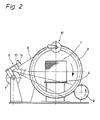
- Fig. 2 dieselbe Vorrichtung in Stranglaufrichtung,
- Fig. 3 eine mögliche Variante der Drahtführung ohne kontinuierliche Seilerneuerung.
- Die Abschneidevorrichtung 2 ist auf einem Schlitten (nicht gezeigt) gelagert, der zum Schneiden des Stranges 1 entweder synchron mit diesem bewegt werden oder stillstehen kann, und mit einem kreisringförmigen Drahtführungskörper 3 ausgerüstet, dessen Drehung durch einen außerhalb gelegenen Antrieb erfolgt.
- Der Strang 1 oder ein Strangstück durchläuft den Drahtführungskörper 3 etwa in dessen Mitte und wird auf einem geschlitzten Schneidetisch 4 transportiert. Der Schneidedraht 5 ist einerseits an einer Drahtbefestigung 10 am kreisringförmigen Drahtführungskörper 3 angebracht und andererseits an einem feststehenden Führungskörper 6 gelagert, der außerhalb des kreisringförmigen Drahtführungskörpers 3 zur Mitte der Stranghöhe ausgerichtet angeordnet ist. Der feststehende Führungskörper 6 weist eine Spule 7 auf, auf die bzw. von der der Schneidedraht auf- bzw. abwickelbar ist und unter gleichmäßiger Spannung gehalten wird.
- Es können auch mehrere Schnittebenen A mit je einem Schneidedraht 5 parallel zum gleichzeitigen Abtrennen mehrerer Formlinge vorgesehen werden, wozu dann an den beiden Führungskörpern eine entsprechende Anzahl von Spulen vorzusehen ist.
- In Fig. 3 ist eine vereinfachte Ausführung für die sägeartige Schnittbewegung dargestellt, bei der am feststehenden Führungskörper 6 der Draht über eine Umlenkrolle 7a geführt und durch ein Gewicht 8 unter gleichbleibender Spannung gehalten wird. Auch hier ist am feststehenden Führungskörper 6 eine Führungs- und Reinigungsleiste für den Draht 5 angelenkt. An der Drahtbefestigung 10 des kreisringförmigen Drahtführungskörpers 3 ist der Draht angelenkt.
Claims (7)
Priority Applications (1)
| Application Number | Priority Date | Filing Date | Title |
|---|---|---|---|
| AT87112620T ATE41345T1 (de) | 1986-10-25 | 1987-08-29 | Abschneidevorrichtung fuer plastische straenge. |
Applications Claiming Priority (2)
| Application Number | Priority Date | Filing Date | Title |
|---|---|---|---|
| DE3636375 | 1986-10-25 | ||
| DE3636375A DE3636375C1 (de) | 1986-10-25 | 1986-10-25 | Abschneidevorrichtung fuer plastische Straenge |
Publications (2)
| Publication Number | Publication Date |
|---|---|
| EP0265628A1 EP0265628A1 (de) | 1988-05-04 |
| EP0265628B1 true EP0265628B1 (de) | 1989-03-15 |
Family
ID=6312473
Family Applications (1)
| Application Number | Title | Priority Date | Filing Date |
|---|---|---|---|
| EP87112620A Expired EP0265628B1 (de) | 1986-10-25 | 1987-08-29 | Abschneidevorrichtung für plastische Stränge |
Country Status (4)
| Country | Link |
|---|---|
| US (1) | US4803905A (de) |
| EP (1) | EP0265628B1 (de) |
| AT (1) | ATE41345T1 (de) |
| DE (1) | DE3636375C1 (de) |
Families Citing this family (6)
| Publication number | Priority date | Publication date | Assignee | Title |
|---|---|---|---|---|
| DE4125556C1 (en) * | 1991-08-02 | 1993-02-25 | Degussa Ag, 6000 Frankfurt, De | Arrangement for sepg. uniform large moulding from extruded plastic material - consisting of rotating cutting element and extruder opening having surrounding crown wheel with wire sections |
| DE59208110D1 (de) * | 1991-11-20 | 1997-04-10 | Sulzer Chemtech Ag | Schneidvorrichtung für eine Extrusionsanlage |
| DE4341812C1 (de) * | 1993-12-08 | 1995-03-23 | Lingl Anlagenbau | Schneidevorrichtung für Tonstrangstücke |
| DE102007049791A1 (de) | 2007-10-17 | 2009-04-23 | Hans Lingl Anlagenbau Und Verfahrenstechnik Gmbh & Co. Kg | Vorrichtung zum Trennen eines längs eines Förderdurchgangs bewegbaren plastischen Stranges, mit wenigstens einem Kerbleisten und Schneidedrahthalter tragendem Trägermodul |
| JP5791270B2 (ja) * | 2010-12-15 | 2015-10-07 | 東芝機械株式会社 | 加熱式工具および工作機械 |
| US20160318171A1 (en) * | 2015-04-30 | 2016-11-03 | Joseph Gonzales | Telescopic saw |
Family Cites Families (11)
| Publication number | Priority date | Publication date | Assignee | Title |
|---|---|---|---|---|
| US1925848A (en) * | 1930-04-07 | 1933-09-05 | Hussmann Ligonier Company | Slicing machine |
| FR787349A (fr) * | 1936-09-04 | 1935-09-20 | Favant Ets | Coupeur automatiques pour briques pleines, tubulaires et tous produits filés |
| US2895514A (en) * | 1954-08-19 | 1959-07-21 | John W Wright | Portable reciprocating power saw |
| DE1584496A1 (de) * | 1964-06-22 | 1970-02-12 | Keller & Co C | Selbsttaetige Abschneidevorrichtung,insbesondere fuer keramische Formlinge |
| NL7010674A (de) * | 1970-07-17 | 1972-01-19 | ||
| DE2100819B1 (de) * | 1971-01-08 | 1972-05-25 | C. Keller U. Co., 4533 Laggenbeck | Einrichtung zum Schneiden von Tonsträngen in Formlinge |
| US4316866A (en) * | 1980-09-26 | 1982-02-23 | R. Martin & Associates | Process and apparatus involving a cutting wire spooling system for cutting brick and tile |
| US4488464A (en) * | 1983-03-28 | 1984-12-18 | Frito-Lay, Inc. | Device for cutting continuous logs of dough |
| DE3434505C1 (de) * | 1984-09-20 | 1986-03-27 | Hebel GmbH Holding, 8080 Emmering | Vorrichtung zum Schneiden eines noch plastischen Porenbetonblockes |
| JPS61237604A (ja) * | 1985-04-13 | 1986-10-22 | 日本碍子株式会社 | セラミック生素地ハニカム構造体の切断装置 |
| US4624163A (en) * | 1985-09-16 | 1986-11-25 | Grace Garland K | Ice cream tub cutter |
-
1986
- 1986-10-25 DE DE3636375A patent/DE3636375C1/de not_active Expired
-
1987
- 1987-08-29 EP EP87112620A patent/EP0265628B1/de not_active Expired
- 1987-08-29 AT AT87112620T patent/ATE41345T1/de not_active IP Right Cessation
- 1987-10-23 US US07/111,740 patent/US4803905A/en not_active Expired - Fee Related
Also Published As
| Publication number | Publication date |
|---|---|
| DE3636375C1 (de) | 1988-01-28 |
| EP0265628A1 (de) | 1988-05-04 |
| US4803905A (en) | 1989-02-14 |
| ATE41345T1 (de) | 1989-04-15 |
Similar Documents
| Publication | Publication Date | Title |
|---|---|---|
| EP0885083B1 (de) | Verfahren zum zerteilen von blöcken aus harten werkstoffen in platten mittels einer drahtsäge und drahtsäge zur durchführung dieses verfahrens | |
| DE3534096C2 (de) | ||
| DE3942671A1 (de) | Drahtsaege zum abtrennen von scheiben von stab- oder blockfoermigen werkstuecken und ihre verwendung | |
| DE3636375C1 (de) | Abschneidevorrichtung fuer plastische Straenge | |
| DE3319935A1 (de) | Edm-schneid-verfahren und -vorrichtung | |
| DE3509338C2 (de) | ||
| AT394508B (de) | Anlage zum herstellen von umreiften drahtgitterrollen | |
| DE2949519C2 (de) | Maschine zum Umschnüren von Packstücken | |
| DE2100819B1 (de) | Einrichtung zum Schneiden von Tonsträngen in Formlinge | |
| DE2506901A1 (de) | Vorrichtung zum zickzackfalten eines bandes | |
| EP0208649B1 (de) | Vorrichtung für einen kurzen Anfahrstrang | |
| DE2412199A1 (de) | Verfahren zur abschnittsweise mit wechselnder drallrichtung bzw. drallaenge erfolgenden verseilung von verseilelementen | |
| DE919284C (de) | Vorrichtung zur Herstellung von Drahtgitterwerken | |
| DE7129507U (de) | Vorrichtung zum Heraustrennen von Profilstücken aus Blöcken aus thermoplastischem Kunststoff, insbesondere aus Schaumstoffblöcken | |
| EP0437231A2 (de) | Umlenkwalze | |
| DE964436C (de) | Abblaseanlage, insbesondere fuer Textilmaschinen | |
| DE2413449A1 (de) | Verfahren zum selbsttaetigen wiederanspinnen eines gebrochenen fadenlaufs | |
| DE3404364C2 (de) | ||
| DE901161C (de) | Selbsttaetige Laengen-Schneidvorrichtung fuer Teigfadenbuendel | |
| DE1113734B (de) | Einrichtung zur kontinuierlichen Herstellung von Isolierschlauch | |
| DE515775C (de) | Verfahren zum Herstellen von Stahlwolle aus Draht | |
| DE834558C (de) | Einrichtung zum Aufhaspeln von aus Metallstrangpressen oder anderen Erzeugungsmaschinen austretenden Draehten oder Baendern | |
| DE2100819C (de) | Einrichtung zum Schneiden von Ton strängen in Formlinge | |
| DE2720933C2 (de) | Verfahren und Vorrichtung zum Schneiden von Ziegelformlingen aus Strangstücken | |
| DE1753694A1 (de) | Verfahren und Vorrichtung zur Herstellung von Kunstleder aus regenerierter Zellulose |
Legal Events
| Date | Code | Title | Description |
|---|---|---|---|
| PUAI | Public reference made under article 153(3) epc to a published international application that has entered the european phase |
Free format text: ORIGINAL CODE: 0009012 |
|
| 17P | Request for examination filed |
Effective date: 19880216 |
|
| AK | Designated contracting states |
Kind code of ref document: A1 Designated state(s): AT BE CH FR GB IT LI NL |
|
| 17Q | First examination report despatched |
Effective date: 19880902 |
|
| GRAA | (expected) grant |
Free format text: ORIGINAL CODE: 0009210 |
|
| AK | Designated contracting states |
Kind code of ref document: B1 Designated state(s): AT BE CH FR GB IT LI NL |
|
| REF | Corresponds to: |
Ref document number: 41345 Country of ref document: AT Date of ref document: 19890415 Kind code of ref document: T |
|
| GBT | Gb: translation of ep patent filed (gb section 77(6)(a)/1977) | ||
| ITF | It: translation for a ep patent filed | ||
| ET | Fr: translation filed | ||
| PLBE | No opposition filed within time limit |
Free format text: ORIGINAL CODE: 0009261 |
|
| STAA | Information on the status of an ep patent application or granted ep patent |
Free format text: STATUS: NO OPPOSITION FILED WITHIN TIME LIMIT |
|
| 26N | No opposition filed | ||
| ITTA | It: last paid annual fee | ||
| PGFP | Annual fee paid to national office [announced via postgrant information from national office to epo] |
Ref country code: AT Payment date: 19970812 Year of fee payment: 11 |
|
| PGFP | Annual fee paid to national office [announced via postgrant information from national office to epo] |
Ref country code: GB Payment date: 19970820 Year of fee payment: 11 |
|
| PGFP | Annual fee paid to national office [announced via postgrant information from national office to epo] |
Ref country code: FR Payment date: 19970827 Year of fee payment: 11 |
|
| PGFP | Annual fee paid to national office [announced via postgrant information from national office to epo] |
Ref country code: CH Payment date: 19970828 Year of fee payment: 11 |
|
| PGFP | Annual fee paid to national office [announced via postgrant information from national office to epo] |
Ref country code: NL Payment date: 19970831 Year of fee payment: 11 |
|
| PGFP | Annual fee paid to national office [announced via postgrant information from national office to epo] |
Ref country code: BE Payment date: 19970911 Year of fee payment: 11 |
|
| PG25 | Lapsed in a contracting state [announced via postgrant information from national office to epo] |
Ref country code: GB Free format text: LAPSE BECAUSE OF NON-PAYMENT OF DUE FEES Effective date: 19980829 Ref country code: AT Free format text: LAPSE BECAUSE OF NON-PAYMENT OF DUE FEES Effective date: 19980829 |
|
| PG25 | Lapsed in a contracting state [announced via postgrant information from national office to epo] |
Ref country code: LI Free format text: LAPSE BECAUSE OF NON-PAYMENT OF DUE FEES Effective date: 19980831 Ref country code: CH Free format text: LAPSE BECAUSE OF NON-PAYMENT OF DUE FEES Effective date: 19980831 Ref country code: BE Free format text: LAPSE BECAUSE OF NON-PAYMENT OF DUE FEES Effective date: 19980831 |
|
| BERE | Be: lapsed |
Owner name: HANS LINGL ANLAGENBAU UND VERFAHRENSTECHNIK G.M.B Effective date: 19980831 |
|
| PG25 | Lapsed in a contracting state [announced via postgrant information from national office to epo] |
Ref country code: NL Free format text: LAPSE BECAUSE OF NON-PAYMENT OF DUE FEES Effective date: 19990301 |
|
| REG | Reference to a national code |
Ref country code: CH Ref legal event code: PL |
|
| GBPC | Gb: european patent ceased through non-payment of renewal fee |
Effective date: 19980829 |
|
| PG25 | Lapsed in a contracting state [announced via postgrant information from national office to epo] |
Ref country code: FR Free format text: LAPSE BECAUSE OF NON-PAYMENT OF DUE FEES Effective date: 19990430 |
|
| NLV4 | Nl: lapsed or anulled due to non-payment of the annual fee |
Effective date: 19990301 |
|
| REG | Reference to a national code |
Ref country code: FR Ref legal event code: ST |
|
| PG25 | Lapsed in a contracting state [announced via postgrant information from national office to epo] |
Ref country code: IT Free format text: LAPSE BECAUSE OF NON-PAYMENT OF DUE FEES;WARNING: LAPSES OF ITALIAN PATENTS WITH EFFECTIVE DATE BEFORE 2007 MAY HAVE OCCURRED AT ANY TIME BEFORE 2007. THE CORRECT EFFECTIVE DATE MAY BE DIFFERENT FROM THE ONE RECORDED. Effective date: 20050829 |