EP0264783B1 - Klappmöbel - Google Patents
Klappmöbel Download PDFInfo
- Publication number
- EP0264783B1 EP0264783B1 EP87114948A EP87114948A EP0264783B1 EP 0264783 B1 EP0264783 B1 EP 0264783B1 EP 87114948 A EP87114948 A EP 87114948A EP 87114948 A EP87114948 A EP 87114948A EP 0264783 B1 EP0264783 B1 EP 0264783B1
- Authority
- EP
- European Patent Office
- Prior art keywords
- legs
- folding
- runners
- folding furniture
- furniture according
- Prior art date
- Legal status (The legal status is an assumption and is not a legal conclusion. Google has not performed a legal analysis and makes no representation as to the accuracy of the status listed.)
- Expired - Lifetime
Links
- 210000001364 upper extremity Anatomy 0.000 claims abstract description 17
- 238000003780 insertion Methods 0.000 claims description 2
- 230000037431 insertion Effects 0.000 claims description 2
- 230000004308 accommodation Effects 0.000 description 2
- 238000006073 displacement reaction Methods 0.000 description 1
- 239000002184 metal Substances 0.000 description 1
- 230000004048 modification Effects 0.000 description 1
- 238000012986 modification Methods 0.000 description 1
- 238000005096 rolling process Methods 0.000 description 1
Images


Classifications
-
- A—HUMAN NECESSITIES
- A47—FURNITURE; DOMESTIC ARTICLES OR APPLIANCES; COFFEE MILLS; SPICE MILLS; SUCTION CLEANERS IN GENERAL
- A47C—CHAIRS; SOFAS; BEDS
- A47C4/00—Foldable, collapsible or dismountable chairs
- A47C4/04—Folding chairs with inflexible seats
- A47C4/08—Folding chairs with inflexible seats having a frame made of wood or plastics
- A47C4/10—Folding chairs with inflexible seats having a frame made of wood or plastics with legs pivotably connected to seat or underframe
- A47C4/12—Folding chairs with inflexible seats having a frame made of wood or plastics with legs pivotably connected to seat or underframe of adjustable type
-
- A—HUMAN NECESSITIES
- A47—FURNITURE; DOMESTIC ARTICLES OR APPLIANCES; COFFEE MILLS; SPICE MILLS; SUCTION CLEANERS IN GENERAL
- A47C—CHAIRS; SOFAS; BEDS
- A47C3/00—Chairs characterised by structural features; Chairs or stools with rotatable or vertically-adjustable seats
- A47C3/02—Rocking chairs
- A47C3/029—Rocking chairs with curved rocking members resting on the floor
Definitions
- the invention relates to folding furniture according to the preamble of patent claim 1.
- the invention relates to folding furniture as a whole, preferably to folding furniture with an adjustable backrest and / or seat, as described in particular in patent application DE-A-36 07 619.
- the invention has for its object to provide a folding furniture of the type mentioned, which can be converted into a rocking chair and can also be folded in this function in a confined space.
- the invention creates a folding piece of furniture, in particular a folding chair, which can be used as a rocking chair or armchair by attaching runners and in doing so retains the originally granted possibility of adjusting the seat inclination and / or backrest inclination, and at the same time together in one form when not in use can be folded with the runners, which due to their compactness requires the least space for accommodation.
- the runners can be easily assembled and disassembled.
- At least one of the cross struts to be provided between the two runners can be used in different positions and thus increases comfort depending on the size of the person using the chair or armchair. It is particularly advantageous that, as a result of the special design of the runners, the armchair can be brought into the fully collapsed state with the runners attached and from the collapsed state to the fully unfolded state with little effort and with minimal force.
- Fig. 1 shows in side view as folding furniture a folding armchair, as described in patent application DE-A-36 07 619 or in patent application DE-A-36 07 581, which has runners according to the invention attached to the lower ends of the legs.
- the folding armchair consists, as usual, of a seat 1, backrest 2, armrests 3, front legs 4, rear legs 5, as well as a cross strut 6 provided between the front legs 4 and a cross strut 7 arranged between the rear legs 5
- Their inclination is adjustable in that a guide and locking mechanism 12 is provided in the area of a connecting device 10, which is preferably arranged laterally between the seat surface 1 and the backrest 2, which enables the seat surface 1, which can be pivoted about an axis of rotation indicated by 13, into different angles of inclination can be adjusted.
- a lateral pin 15 protrudes from the connecting device 10 into a guide groove 16 with different locking grooves 17a, 17b and, by adjusting the pin 15 into the different locking grooves, causes a change in the inclination of the seat surface 1.
- this is described in patent application DE-A -36 07 619.
- the armrest 3 can be adjustable to adjust the inclination of the backrest 2, as is also specified in the patent application DE-A-36 07 619.
- Such a folding armchair can be folded into a very compact form for storage.
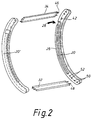
- the folding armchair described with reference to FIG. 1 can be converted into a rocking armchair by attaching runners 20 to the lower sections of its legs 4, 5.
- the runners 20 have a substantially curved course and are preferably designed to run straight at their end sections designated 22a, 22b with respect to the downward-facing bearing surface, which means that when the rocking chair is used, the straight-lying bearing surfaces cause it to tip over 22a, 22b is prevented. Between the areas 22a, 22b, the contact surface of each runner 20 is curved in an arcuate or elliptical manner.
- the runners 20 are each attached from the side to the lower ends of the legs 4, 5.
- the two runners 20 can be easily and quickly assembled or disassembled from the legs 4, 5 by connecting elements to be described.
- the ends of the rear legs 5 are rotatably attached to the end area of one runner 20, while the lower ends of the front legs 4 are adjustable relative to the runner 20.
- a guide element 24 is provided at the lower end of the two front legs 4, which protrudes laterally from the legs 4 and protrudes into a guide groove 26 which extends over the predominant length of the runner 20 and in the inner surface of each runner 20.
- the runners 20 can be attached to the inner surfaces of the legs 4, 5; in this case, each guide groove 26 is located on the outward-facing surface of each runner 20 and the guide element 24 in this case protrudes laterally inwards away from the inner surface of each front leg 4.
- the guide groove 26 has an arcuate course such that this arcuate course corresponds to the path of movement of the guide element 24, which it is when folding the folding chair due to the movement of the two pairs of legs 4, 5 towards each other up to the position shown in Fig. 3 in relation to the rear leg 5 drives through.
- the guide groove 26 extends so far in the direction of the area 22a that any adjustment of the folding armchair and the adjustment of the seat 1, which may result in a spreading of the associated pairs of legs 4, 5 against one another, is possible with the runners 20 attached.
- each guide groove 26 has an approximately slot-shaped opening 28 to the contact edge of each runner 20, designated 30 in FIG. 1.
- This slot-shaped opening 28 preferably has a conically widening shape from the guide groove 26 in the direction of the bearing surface 30.
- the slot-shaped opening 28 lies in the plane of the groove 26 and extends laterally away from it at one end of the groove 26.
- cross struts 32, 34 can be used between the pairs of runners according to FIG. 2, the pairs of runners being designated 20 ⁇ and 20 ⁇ in FIG. 2.
- the folding of the folding armchair is carried out in such a way that the folding armchair is adjusted from the position shown in FIG. 1 by pivoting the seat surface 1 in the direction of the backrest 2. Since the seat 1 in the embodiment shown is rotatably mounted on the front legs 4 in the region of the axis of rotation 13 and, at the same time, the armrest 3 in the embodiment shown is rotatably mounted laterally on the backrest 2 at 36, and the respective front legs and rear legs 4, 5 above an only indicated link 38 are connected to each other, causes the folding of the seat 1 on the backrest 2, or vice versa, that the pair of front legs 4 and the pair of rear legs 5 are brought into a substantially parallel position and in contact with each other, so that the state shown in Fig. 3 is reached.
- the guide elements 24 attached to the lower ends of the front legs 4 move backward within the guide groove 26, ie in the direction of the opening 28, and reach the position within the slot 28 indicated by dashed lines and indicated by the reference numeral 24 ⁇ Reaching the parallel position of the front and rear pairs of legs as shown in Fig. 3.
- Folding the folding chair also causes the pair of runners opposite an axis of rotation 40 of the rear legs 5 performs a pivoting movement such that the angle between the rear pair of legs 5 and the pair of runners 20 becomes smaller and smaller and the runners 20 move about the axis of rotation 40 into the position shown in FIG. 3 before the guide pin 24 by completely collapsing and the movement of the legs 5, 6 in the parallel position shown in FIG. 3 emerges from the opening 28.
- the runners 20 come to lie almost in the plane of the front and rear pairs of legs 4, 5 and, in the preferred folding armchair shown in connection with FIGS. 1 and 3, are in contact with the lower area of the armrest 3 at their front area
- an extremely compact shape is guaranteed, including the articulated runners, which ensures space-saving accommodation of the folded folding armchair or rocking armchair.
- the lower ends of the rear legs 5 are rotatable in the region of the axis of rotation denoted by 40 and are fixedly connected to the runners 20 by connecting elements 42, while the front legs 4 are guided so as to be adjustable in the longitudinal direction of the runners 20.
- the arrangement can also be reversed, i.e. that the runners 20 are rotatably mounted on the lower ends of the front legs 4, while the lower ends of the rear legs 5 are guided along the runners.
- the runners rest on the support surface of the armrests 3.
- FIG. 3 in connection with FIG. 1 is preferred, since in this embodiment an extremely compact shape can be achieved in the folded state.
- the front cross strut 32 can be provided at different distances from the front end of the pair of runners, as by the reference symbol 32 ⁇ is indicated.
- the cross strut 32 can be provided at the point 32, ie far at the front end of the pair of runners 20, if this cross strut is to serve as a footrest or for supporting the feet. If the cross strut 32 is not intended to serve as a footrest and the front area between the footrests should be as free as possible from such a strut in order to avoid a collision with the feet of the chair user, the cross strut is used in a position as close as possible to the end of the front legs 4 provided and indicated with 32 ⁇ .
- Each cross strut 32, 34 for example, has pins 46, 48 which can be inserted into associated bores on the inner surface of the runners 20.
- screws are preferably used in order to firmly connect the cross struts 32, 34 to the runners 20.
- other types of fastening can be used for the fixed arrangement of the struts 32, 34 between the runners 20.
- the bores in the runners 20 corresponding to the item 32 in FIG. 1 are designated by 50 and the bores in the runners 20 corresponding to the item 32 ⁇ are designated by 52.
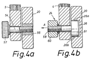
- 4a shows a sectional view along the line IVa-IVa in FIG. 1 for a preferred embodiment of the rotatable fixed mounting of the lower ends of the rear legs 5 relative to the runners 20.
- each rear leg 5 is positioned opposite the runner 20 on the inwardly facing surface of the runner 20.
- the lower end of each rear leg 5 is connected by a connecting element 54, e.g. B. in the form of a screw or knurled screw rotatably with respect to the runner 20, for which purpose the runner 20 has a sleeve 56 with an internal thread, into which the screw 54 is screwed with its threaded area.
- the the area of the connecting element 54 passing through the rear leg 5 preferably has no external thread and is provided at its end facing away from the runner 20 with a head or knurled head 57 which holds the leg 5 rotatably with respect to the runner 20 as soon as the screw 54 into the threaded sleeve 56 is screwed in. If necessary, a metal washer should be provided in the area of the screw connection 54 and between the head 57 and the inner leg 5 to reduce the frictional forces.
- each front leg 4 is slidably supported in the guide groove 26 by a connecting or guiding element 24.
- a screw bolt is provided as the connecting or guide element 24, the head 61 of which has a smaller diameter than the width of the guide groove 26 and is provided with an external thread 58 at its end facing away from the head 61.
- the bolt 24 is passed through a hole in the lower end of the front leg 4 in question and is secured against the lower leg, for example by a nut or a knurled head 60, which is screwed onto the end of the bolt.
- the guide element 24 can thus be slidably inserted into the guide groove 26 by its head, designated 61, and is mounted within the guide groove 26 so as to be displaceable toward one another when the legs or pairs of legs 4, 5 move.
- the guide element 24 can optionally perform a sliding or rolling movement with its head 61 relative to the upper or lower groove walls 26a, 26b of the guide groove 26 facing it, for which purpose the head 61 is preferably cylindrical is. It can be seen that the head 61 is supported by the guide groove 26 so that it can move laterally out of the guide groove 26.
- the essentially U-shaped guide groove 26 does not prevent the guide element 24 from moving in the direction of an arrow A.
- the guide groove 26 can have a dovetail profile, for example, so that the underside of the head 61 slidably rests on the dovetail guide and lateral displacement of the guide element 24 out of the guide groove 26 is avoided.
- a bore corresponding to the diameter of the head 61 is to be provided at a predetermined position of the guide groove in order to allow the insertion or removal of the guide element 24.
- the invention thus creates a folding armchair that can be converted into a rocking armchair by attaching runners and still allows the possible adjustment options, such as adjusting the inclination of the backrest and / or the seat, to be carried out.
- the inventive design of the guide grooves in the two runners allows the folding armchair to be folded into an extremely compact shape when the runners are attached, the course of the guide groove being chosen such that an outwardly extending, preferably conically widening slot is provided at a predetermined position 3, for the purpose of completely collapsing into the shape shown in FIG. 3, allowing the guide element 24 to emerge from the groove 26 and thus ensuring that the end of each runner located in FIG. 3 to the axis of rotation 40 is close to the front edge of the corresponding one Armrest 3 comes to the system, which ensures the compact shape of the folding chair in the folded state.
- a folding armchair for the purpose of using the rocking runners in the area of its legs 4, 5 only has to be provided with transverse bores for carrying out the connecting elements 24 54 serve, while the runners for fastening the connecting elements 54 are provided at a predetermined point with a bore into which a threaded sleeve 56, which has, for example, an internal and external thread, can be screwed.
- the guide element denoted by 24 in FIG. 4b is designed such that the lowest possible frictional resistance occurs between the guide element 24 and the guide groove 26 and thus easy folding of the folding chair with simultaneous movement of the lower end of the front legs 4 along the guide groove 26 in the direction of the rear pair of legs 5 is reached.
Landscapes
- Life Sciences & Earth Sciences (AREA)
- Engineering & Computer Science (AREA)
- Wood Science & Technology (AREA)
- Chairs For Special Purposes, Such As Reclining Chairs (AREA)
- Chairs Characterized By Structure (AREA)
- Special Chairs (AREA)
- Laminated Bodies (AREA)
- Sheet Holders (AREA)
- Chair Legs, Seat Parts, And Backrests (AREA)
Priority Applications (1)
| Application Number | Priority Date | Filing Date | Title |
|---|---|---|---|
| AT87114948T ATE70957T1 (de) | 1986-10-14 | 1987-10-13 | Klappmoebel. |
Applications Claiming Priority (2)
| Application Number | Priority Date | Filing Date | Title |
|---|---|---|---|
| DE3635003 | 1986-10-14 | ||
| DE19863635003 DE3635003A1 (de) | 1986-10-14 | 1986-10-14 | Klappmoebel |
Publications (3)
| Publication Number | Publication Date |
|---|---|
| EP0264783A2 EP0264783A2 (de) | 1988-04-27 |
| EP0264783A3 EP0264783A3 (en) | 1988-07-20 |
| EP0264783B1 true EP0264783B1 (de) | 1992-01-02 |
Family
ID=6311719
Family Applications (1)
| Application Number | Title | Priority Date | Filing Date |
|---|---|---|---|
| EP87114948A Expired - Lifetime EP0264783B1 (de) | 1986-10-14 | 1987-10-13 | Klappmöbel |
Country Status (5)
| Country | Link |
|---|---|
| US (1) | US4807926A (OSRAM) |
| EP (1) | EP0264783B1 (OSRAM) |
| JP (1) | JPS63111816A (OSRAM) |
| AT (1) | ATE70957T1 (OSRAM) |
| DE (2) | DE3635003A1 (OSRAM) |
Families Citing this family (18)
| Publication number | Priority date | Publication date | Assignee | Title |
|---|---|---|---|---|
| EP0551004A2 (en) * | 1992-01-07 | 1993-07-14 | Kazumi Kamachi | Self-locking mounting bolt systems for furniture |
| DE4236996C2 (de) * | 1992-11-02 | 1996-05-23 | Le Griffon Jean Bernard | Zusammenklappbarer Schaukelstuhl |
| US5560675A (en) * | 1994-01-13 | 1996-10-01 | Bemis Manufacturing Company | Folding rocking chair |
| GB2287182A (en) * | 1994-03-08 | 1995-09-13 | Andrew Meek | Rocking reclining chair |
| US5435622A (en) * | 1994-05-05 | 1995-07-25 | La-Z-Boy Chair Company | Swivel recliner/rocker chair having preloaded base assembly |
| CA2171371C (en) * | 1996-03-08 | 1999-12-21 | Donald Shaw | Convertible rocker |
| USD380633S (en) * | 1996-03-14 | 1997-07-08 | Donald Shaw | Rocker attachment |
| US6540292B2 (en) * | 1999-05-28 | 2003-04-01 | Mattel, Inc. | Adjustable rocker seat |
| US7100975B1 (en) | 2000-08-30 | 2006-09-05 | Tofasco Of America, Inc. | Collapsible rocking chair |
| GB2382523B (en) * | 2001-11-30 | 2003-11-05 | Link Treasure Ltd | A structure for an infant's rocker |
| ITMI20021897A1 (it) * | 2002-09-06 | 2004-03-07 | Peg Perego Spa | Seggiolone con dondolo per bambini. |
| US7527560B2 (en) * | 2004-12-08 | 2009-05-05 | Joseph B. Taphorn | Steerable walking rocking horse |
| CN104223818A (zh) * | 2013-06-07 | 2014-12-24 | 汪芳 | 折叠式躺坐健康椅 |
| US9782006B2 (en) * | 2015-06-01 | 2017-10-10 | Recreational Equipment, Inc. | Collapsible rocking chair |
| CN105054633A (zh) * | 2015-07-31 | 2015-11-18 | 韩玉生 | 一种方便折叠的座椅 |
| CN105054630A (zh) * | 2015-07-31 | 2015-11-18 | 韩玉生 | 一种实木座椅 |
| CN108784064B (zh) * | 2018-06-29 | 2021-09-14 | 浙江快绿洁塑业有限公司 | 一种简便的摇摇椅 |
| US10993537B1 (en) * | 2020-04-28 | 2021-05-04 | Carl Lujan | Rocking chair base with pivot point |
Family Cites Families (10)
| Publication number | Priority date | Publication date | Assignee | Title |
|---|---|---|---|---|
| FR963088A (OSRAM) * | 1950-06-30 | |||
| CH1860A (de) * | 1890-02-07 | 1890-05-31 | Adolf Bader | Zusammenlegbares Gestell mit Regulirvorrichtung für Schaukelstühle und Schaukelschemel |
| CH139468A (de) * | 1929-04-03 | 1930-04-30 | Enders Osmar | Zusammenleg- und verstellbarer Schaukelliegestuhl. |
| US2072075A (en) * | 1935-02-07 | 1937-02-23 | Mahoney Chair Company | Folding chair |
| US2715937A (en) * | 1954-06-15 | 1955-08-23 | Clifford S Lupercio | Collapsible rocker |
| US3048440A (en) * | 1960-12-27 | 1962-08-07 | David M Mcpherson | Folding rocking chair |
| US3114572A (en) * | 1961-11-16 | 1963-12-17 | Balcrank Inc | Folding rocking chair |
| US3269771A (en) * | 1965-07-01 | 1966-08-30 | Erdos Edmund | Convertible chair |
| DE1963053U (de) * | 1967-01-31 | 1967-06-29 | Ernst Dipl Ing Lepper | Zusammenklappbarer lehnsessel mit schaukelgestell und bespannung (schaukelsessel). |
| US3671072A (en) * | 1969-07-31 | 1972-06-20 | Chester H Holt | Folding rocking chair with folding seat support |
-
1986
- 1986-10-14 DE DE19863635003 patent/DE3635003A1/de not_active Withdrawn
-
1987
- 1987-10-12 JP JP62257046A patent/JPS63111816A/ja active Granted
- 1987-10-13 EP EP87114948A patent/EP0264783B1/de not_active Expired - Lifetime
- 1987-10-13 US US07/108,194 patent/US4807926A/en not_active Expired - Fee Related
- 1987-10-13 DE DE8787114948T patent/DE3775697D1/de not_active Expired - Lifetime
- 1987-10-13 AT AT87114948T patent/ATE70957T1/de not_active IP Right Cessation
Also Published As
| Publication number | Publication date |
|---|---|
| EP0264783A3 (en) | 1988-07-20 |
| US4807926A (en) | 1989-02-28 |
| ATE70957T1 (de) | 1992-01-15 |
| DE3635003A1 (de) | 1988-04-21 |
| EP0264783A2 (de) | 1988-04-27 |
| DE3775697D1 (de) | 1992-02-13 |
| JPH0458327B2 (OSRAM) | 1992-09-17 |
| JPS63111816A (ja) | 1988-05-17 |
Similar Documents
| Publication | Publication Date | Title |
|---|---|---|
| EP0264783B1 (de) | Klappmöbel | |
| EP0236891B1 (de) | Klappmöbel | |
| DE3637362C2 (OSRAM) | ||
| DE69327907T2 (de) | Sicherheitsmehrzweckmesser | |
| EP0179357A2 (de) | Sitzmöbel | |
| DE3235361A1 (de) | Arretierbare wippvorrichtung fuer sitzteile von sitzmoebeln | |
| DE602004007956T2 (de) | Selbststabilisierende stützanordnung für ein möbelstück | |
| EP3113743B1 (de) | Aufrichtrollstuhl | |
| DE3445885A1 (de) | Scharnier | |
| DE2736550A1 (de) | Vorrichtung zur verstellung der neigung des sitzpolsters bei einem fahrersitz, buerostuhl, drehsessel o.dgl. | |
| AT523440B1 (de) | Scharnieranordnung | |
| EP0775458A1 (de) | Stuhl mit Kniestütze | |
| DE3416485C2 (de) | Ausstelldach für ein Fahrzeug | |
| DE69508618T2 (de) | Klappstuhl | |
| DE2721539A1 (de) | Fahrzeugsitz | |
| DE3130444C2 (de) | Fahrzeugsitz | |
| DE6602305U (de) | Stuhleinstellvorrichtung | |
| EP0264607B1 (de) | Klappmöbel | |
| DE102017205699A1 (de) | Vorrichtung zum Kippen der Rückenlehne von Bürostühlen | |
| DE102023205956A1 (de) | Kindertransporter | |
| DE2808381C2 (de) | Kopfstütze für einen Sitz, insbesondere Kraftfahrzeugsitz | |
| DE69118293T2 (de) | Neigbarer Kindersitz | |
| DE3433590C2 (OSRAM) | ||
| WO1999007257A2 (de) | Stuhl | |
| DE843005C (de) | Klappstuhl |
Legal Events
| Date | Code | Title | Description |
|---|---|---|---|
| PUAI | Public reference made under article 153(3) epc to a published international application that has entered the european phase |
Free format text: ORIGINAL CODE: 0009012 |
|
| AK | Designated contracting states |
Kind code of ref document: A2 Designated state(s): AT BE CH DE ES FR GB GR IT LI LU NL SE |
|
| PUAL | Search report despatched |
Free format text: ORIGINAL CODE: 0009013 |
|
| AK | Designated contracting states |
Kind code of ref document: A3 Designated state(s): AT BE CH DE ES FR GB GR IT LI LU NL SE |
|
| 17P | Request for examination filed |
Effective date: 19890120 |
|
| 17Q | First examination report despatched |
Effective date: 19900105 |
|
| GRAA | (expected) grant |
Free format text: ORIGINAL CODE: 0009210 |
|
| AK | Designated contracting states |
Kind code of ref document: B1 Designated state(s): AT BE CH DE ES FR GB GR IT LI LU NL SE |
|
| PG25 | Lapsed in a contracting state [announced via postgrant information from national office to epo] |
Ref country code: IT Free format text: LAPSE BECAUSE OF FAILURE TO SUBMIT A TRANSLATION OF THE DESCRIPTION OR TO PAY THE FEE WITHIN THE PRE;WARNING: LAPSES OF ITALIAN PATENTS WITH EFFECTIVE DATE BEFORE 2007 MAY HAVE OCCURRED AT ANY TIME BEFORE 2007. THE CORRECT EFFECTIVE DATE MAY BE DIFFERENT FROM THE ONE RECORDED.SCRIBED TIME-LIMIT Effective date: 19920102 Ref country code: SE Effective date: 19920102 Ref country code: NL Effective date: 19920102 Ref country code: GR Free format text: LAPSE BECAUSE OF FAILURE TO SUBMIT A TRANSLATION OF THE DESCRIPTION OR TO PAY THE FEE WITHIN THE PRESCRIBED TIME-LIMIT Effective date: 19920102 Ref country code: FR Effective date: 19920102 Ref country code: BE Effective date: 19920102 Ref country code: GB Effective date: 19920102 |
|
| REF | Corresponds to: |
Ref document number: 70957 Country of ref document: AT Date of ref document: 19920115 Kind code of ref document: T |
|
| REF | Corresponds to: |
Ref document number: 3775697 Country of ref document: DE Date of ref document: 19920213 |
|
| PG25 | Lapsed in a contracting state [announced via postgrant information from national office to epo] |
Ref country code: ES Free format text: LAPSE BECAUSE OF FAILURE TO SUBMIT A TRANSLATION OF THE DESCRIPTION OR TO PAY THE FEE WITHIN THE PRESCRIBED TIME-LIMIT Effective date: 19920413 |
|
| EN | Fr: translation not filed | ||
| NLV1 | Nl: lapsed or annulled due to failure to fulfill the requirements of art. 29p and 29m of the patents act | ||
| GBV | Gb: ep patent (uk) treated as always having been void in accordance with gb section 77(7)/1977 [no translation filed] | ||
| PGFP | Annual fee paid to national office [announced via postgrant information from national office to epo] |
Ref country code: DE Payment date: 19921028 Year of fee payment: 6 |
|
| PG25 | Lapsed in a contracting state [announced via postgrant information from national office to epo] |
Ref country code: LU Free format text: LAPSE BECAUSE OF NON-PAYMENT OF DUE FEES Effective date: 19921031 |
|
| PLBE | No opposition filed within time limit |
Free format text: ORIGINAL CODE: 0009261 |
|
| STAA | Information on the status of an ep patent application or granted ep patent |
Free format text: STATUS: NO OPPOSITION FILED WITHIN TIME LIMIT |
|
| 26N | No opposition filed | ||
| PG25 | Lapsed in a contracting state [announced via postgrant information from national office to epo] |
Ref country code: DE Effective date: 19940701 |
|
| PGFP | Annual fee paid to national office [announced via postgrant information from national office to epo] |
Ref country code: CH Payment date: 19970121 Year of fee payment: 10 |
|
| PG25 | Lapsed in a contracting state [announced via postgrant information from national office to epo] |
Ref country code: LI Free format text: LAPSE BECAUSE OF NON-PAYMENT OF DUE FEES Effective date: 19971031 Ref country code: CH Free format text: LAPSE BECAUSE OF NON-PAYMENT OF DUE FEES Effective date: 19971031 |
|
| REG | Reference to a national code |
Ref country code: CH Ref legal event code: PL |
|
| PGFP | Annual fee paid to national office [announced via postgrant information from national office to epo] |
Ref country code: AT Payment date: 19980924 Year of fee payment: 12 |
|
| PG25 | Lapsed in a contracting state [announced via postgrant information from national office to epo] |
Ref country code: AT Free format text: LAPSE BECAUSE OF NON-PAYMENT OF DUE FEES Effective date: 19991013 |