EP0264105A2 - Verfahren zur Herstellung einer mehrschichtigen Leiterplatte mit metallischem Kern - Google Patents
Verfahren zur Herstellung einer mehrschichtigen Leiterplatte mit metallischem Kern Download PDFInfo
- Publication number
- EP0264105A2 EP0264105A2 EP87114945A EP87114945A EP0264105A2 EP 0264105 A2 EP0264105 A2 EP 0264105A2 EP 87114945 A EP87114945 A EP 87114945A EP 87114945 A EP87114945 A EP 87114945A EP 0264105 A2 EP0264105 A2 EP 0264105A2
- Authority
- EP
- European Patent Office
- Prior art keywords
- wiring board
- multilayer printed
- product portion
- metal plate
- peripheral portion
- Prior art date
- Legal status (The legal status is an assumption and is not a legal conclusion. Google has not performed a legal analysis and makes no representation as to the accuracy of the status listed.)
- Withdrawn
Links
Images


Classifications
-
- H—ELECTRICITY
- H05—ELECTRIC TECHNIQUES NOT OTHERWISE PROVIDED FOR
- H05K—PRINTED CIRCUITS; CASINGS OR CONSTRUCTIONAL DETAILS OF ELECTRIC APPARATUS; MANUFACTURE OF ASSEMBLAGES OF ELECTRICAL COMPONENTS
- H05K3/00—Apparatus or processes for manufacturing printed circuits
- H05K3/44—Manufacturing insulated metal core circuits or other insulated electrically conductive core circuits
- H05K3/445—Manufacturing insulated metal core circuits or other insulated electrically conductive core circuits having insulated holes or insulated via connections through the metal core
-
- H—ELECTRICITY
- H05—ELECTRIC TECHNIQUES NOT OTHERWISE PROVIDED FOR
- H05K—PRINTED CIRCUITS; CASINGS OR CONSTRUCTIONAL DETAILS OF ELECTRIC APPARATUS; MANUFACTURE OF ASSEMBLAGES OF ELECTRICAL COMPONENTS
- H05K3/00—Apparatus or processes for manufacturing printed circuits
- H05K3/46—Manufacturing multilayer circuits
- H05K3/4611—Manufacturing multilayer circuits by laminating two or more circuit boards
- H05K3/4641—Manufacturing multilayer circuits by laminating two or more circuit boards having integrally laminated metal sheets or special power cores
-
- H—ELECTRICITY
- H05—ELECTRIC TECHNIQUES NOT OTHERWISE PROVIDED FOR
- H05K—PRINTED CIRCUITS; CASINGS OR CONSTRUCTIONAL DETAILS OF ELECTRIC APPARATUS; MANUFACTURE OF ASSEMBLAGES OF ELECTRICAL COMPONENTS
- H05K2201/00—Indexing scheme relating to printed circuits covered by H05K1/00
- H05K2201/09—Shape and layout
- H05K2201/09209—Shape and layout details of conductors
- H05K2201/09654—Shape and layout details of conductors covering at least two types of conductors provided for in H05K2201/09218 - H05K2201/095
- H05K2201/0969—Apertured conductors
-
- H—ELECTRICITY
- H05—ELECTRIC TECHNIQUES NOT OTHERWISE PROVIDED FOR
- H05K—PRINTED CIRCUITS; CASINGS OR CONSTRUCTIONAL DETAILS OF ELECTRIC APPARATUS; MANUFACTURE OF ASSEMBLAGES OF ELECTRICAL COMPONENTS
- H05K2203/00—Indexing scheme relating to apparatus or processes for manufacturing printed circuits covered by H05K3/00
- H05K2203/14—Related to the order of processing steps
- H05K2203/143—Treating holes before another process, e.g. coating holes before coating the substrate
-
- H—ELECTRICITY
- H05—ELECTRIC TECHNIQUES NOT OTHERWISE PROVIDED FOR
- H05K—PRINTED CIRCUITS; CASINGS OR CONSTRUCTIONAL DETAILS OF ELECTRIC APPARATUS; MANUFACTURE OF ASSEMBLAGES OF ELECTRICAL COMPONENTS
- H05K3/00—Apparatus or processes for manufacturing printed circuits
- H05K3/0011—Working of insulating substrates or insulating layers
- H05K3/0044—Mechanical working of the substrate, e.g. drilling or punching
- H05K3/0052—Depaneling, i.e. dividing a panel into circuit boards; Working of the edges of circuit boards
Definitions
- the present invention relates to a multilayer printed-wiring board using copper cores as inner conductor layers, and, more particularly, to a method of producing a multilayer printed-wiring board which is suitable for ensuring an insulation at the end surfaces of the board or between its inner conductor layers.
- Figs. 9A to 9F show a multilayer printed-wiring board disclosed in Japanese Patent Application Laid-Open Publication No. 219795/85.
- Fig. 9A shows a board 11 in a state wherein copper cores and layers of insulating material are laminated together.
- the board 11 has a product portion 2, with a non-product portion 3 surrounding the product portion 2 and monolithically formed with the product portion 2.
- a two-dot dashed line 6 indicates a line along which the board 11 is to be separated into the product portion 2 and the non-product portion 3.
- Fig. 9B which is a cross-section taken along the line Z - Z ⁇ in Fig.
- Fig. 9A copper cores 1c and 1d and outer layers 7a and 7b are interleaved with prepregs 8 and laminated together to form the board 11.
- An arrow 6 indicates the position at which the board 11 is cut.
- Fig. 9c shows a multilayer printed-wiring board 12 after it has been cut
- Fig. 9D is a cross-section taken along the line Y - Y ⁇ in Fig. 9C. As can be seen from Fig. 9D, the copper cores 1c and 1d are exposed at the end surfaces of the board 12.
- a portion 13a at the end surface of the copper cores is worked by a NC milling machine or the like, and thereafter, as shown in Fig. 9F, the portion 13a is coated with an insulating resin 13b to prevent the copper cores from being exposed.
- the known technique also has a disadvantage in that, if the formed printed-wiring board is of a type which has two or more copper cores located close to each other, the copper cores may form burrs or become sagged when the external form is cut out or when the side surfaces are worked afterwords, thereby short-circuiting the copper cores.
- the known technique generally employs copper cores which have a thickness of 100 ⁇ m to 500 ⁇ m, the resistance to cutting out the external form becomes increased, thereby deteriorating the machinability.
- an object of the present invention is to provide a method of producing a multilayer printed-wiring board containing as an inner layer plate at least one metal plate which does not allow the inner metal plate to be exposed from the side of the product board when a peripheral portion which is a non-product portion is separated from a product portion surrounded by the peripheral portion after the formation of a multilayer body.
- the present invention provides a method of producing a multilayer printed-wiring board containing as an inner layer plate at least one metal plate, which comprises the steps of: forming a metal plate having a peripheral portion which is a non-product portion, and a product portion surrounded by the peripheral portion, the peripheral portion and the product portion being partially connected; filling an insulating material into non-connecting portions formed between the peripheral portion and the product portion; laminating the metal plate with another inner layer plates to form a multilayer body; and separating the peripheral portion from the product portion within the regions in which the insulating material is filled.
- Fig. 1 shows a metal plate to be contained in a multilayer printed-wiring board according to a first embodiment of the present invention.
- the metal plate is formed of a copper core 1 which has a thickness of 100 ⁇ m or more.
- the copper core 1 has: a peripheral, non-product portion 3 wich is to be cut off in a subsequent process; a product portion 2 which is to be used as a product and on which a circuit pattern (for example, clearances between through-holes, which are not shown to simplify the illustration) is formed; connecting portions 4 which connect the product portion 2 and the peripheral portion 3; and slits 16 for separating the product portion 2 from the peripheral portion 3, the slits 16 being filled with an insulating resin.
- This copper core 1 is produced in the following way: namely, in order to form the product portion 2, peripheral portion 3, and connecting portions 4, as well as the circuit pattern to be formed within the product portion 2, the upper and lower surfaces of the copper plate are coated with resist film according to the respective shapes of these portions and the circuit pattern. The copper plate is then etched to form each portion and the circuit pattern. Subsequently, an insulating resin 10 is filled into the slits 16 formed by the etching.
- Fig. 1B is a cross-section taken along the line O - O ⁇ in Fig. 1A. As can be seen from the figure, the slits 16 are filled with the insulating resin 10.
- the thus-obtained copper cores are stacked to form a multilayer printed-wiring board.
- Fig. 2A shows a multilayer body 20 containing the copper cores 1.
- An hatched region in Fig. 2A corresponds to the copper cores 1.
- Fig. 2B is a cross-section taken along the line P - P ⁇ in Fig. 2A.
- the multilayer body 20 is formed of the copper cores 1, prepregs 7 and outer layer plates 5, the copper cores 1 being interleaved with the prepregs 7 and being bonded to the outer layer plates 5 to form the multilayer body 20.
- the resulting multilayer body comprises a multilayer printed-wiring board 9 constituting the portion of the multilayer body which is located inside a dot dashed line 11, and a carrier frame 15 constituting a portion located outside the dot dashed line 11.
- the thus-obtained multilayer body 20 is provided with required through-holes, and then the surface of each of the outer layers is electroless-plated or electroplated to form plated layers thereon. Each of the plated layers is then coated with resist film, and etched to form the desired circuit pattern.
- the multilayer printed-wiring board 9 is separated from the carrier frame 15 which is the peripheral portion by cutting the multilayer body 20 along the dot dashed line 11 shown in Fig. 2A by a cutter.
- the cutting along the dot dashed line 11 is carried out in such a manner that part of the insulating resin 10 filling the slits 16 is left on the edges of the multilayer printed-wiring board 9.
- the regions of the connecting portions 4 are cut along the dot dashed line 11 in such a manner that recesses are formed on the edges of the multilayer printed-wiring board 9.
- a multilayer printed wiring board is obtained in which most of the peripheries of the inner conductor layers are covered with the remaining insulating resin, with the exposed portions of the same being recessed so that the power source layer or ground layer of the multilayer printed-wiring board cannot short-circuit to the frame of the casing into which the multilayer printed-wiring boards are packaged.
- the multilayer printed-wiring board 9 of this embodiment comprises the multilayer printed-wiring board 9 shown in Fig. 2A, with pads 8 formed as the recesses thereof.
- the pads 8 are electrically connected to the inner copper cores 1, and are therefore formed in such a manner that they do not protrude from the sides of the multilayer printed-wiring board 9.
- each of the connecting portions 4 is cut off by drilling in such a manner that a recess is formed in the multilayer printed-wiring board 9.
- Each surface of the outer layer plates is then electroless-plated or electroplated in the same manner as in the first embodiment to form plated surfaces which are coated with resist film and etched to form the desired pattern.
- each of the recessed portions is provided with an outer layer pad 8 which is large enough for its eventual purpose, but which is formed so that its formation does not make the recess bulge from the multilayer printed-wiring board 9.
- the carrier frame 15 is separated by cutting the multilayer body 20 along the dot dashed line 11 by a cutter.
- the recessed portion of the multilayer printed-wiring board 9 constitutes the pad connected to the inner copper cores, the recessed portion can be used as power supply groove. Further, since the other peripheral portions of the multilayer printed-wiring board are covered with the insulating resin, short-circuiting of the inner copper cores to the frame of the casing can be prevented.
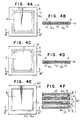
- FIGs. 4A and 4C show a copper core 1a and a copper core 1b, respectively.
- the copper core 1a has connecting portions 4a and the copper core 1b has connecting portions 4b which are not located at positions corresponding to those of the connecting portions 4a, so that the connecting portions 4a and 4b are not aligned when the two copper cores 1a and 1b are stacked. This can be seen more clearly by comparing the cross-sections of the copper cores 1a and 1b.
- Figs. 4B and 4D are cross-sections taken along the lines A - A ⁇ and B - B ⁇ in Figs. 4A and 4C, respectively.
- the connecting portions 4a of the copper core 1a are aligned to insulating resin filling the slits of the copper core 1b.
- Fig. 4E shows the multilayer body 20 fabricated from the copper cores 1a and 1b, the outer layer plates 5 and the prepregs 7.
- Fig. 4F is a cross-section taken along the line C - C ⁇ in Fig. 4E. The thus-obtained multilayer body 20 is then separated along the dot dashed line 11 shown in Fig. 4E.
- the non-alignment of the connecting portions 4a and 4b of the multilayer printed-wiring board 9 in this embodiment can effectively prevent short-circuiting between the inner copper cores or insulation failure which would occur if the coppers in the connecting portions 4a and 4b become sagged or burred when the multilayer printed-wiring board 9 is cut out.
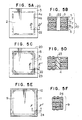
- a multilayer printed-wiring board of this embodiment comprises the multilayer body 20 of the third embodiment which is modified so that the connecting portions 4a and 4b are cut off before the external form of the multilayer body 20 is cut out and that insulating resin is filled into the holes formed after the connecting portions 4a and 4b have been removed so that the copper cores are not exposed after the external form of the multilayer body 20 is cut out.
- Fig. 5A shows the multilayer body 20 having portions 22 which contain the connecting portions 4a and 4b. The portions 22 are cut by a NC router.
- Fig. 5B is a cross-section taken along the line D - D ⁇ in Fig. 5A, showing the multilayer body 20 in which the portion 22 has been cut off to remove the connecting portion 4a and separate the product portion 2 from the peripheral portion 3.
- Fig. 5D is a cross-section taken along the line E - E ⁇ in Fig. 5C.
- the multilayer printed-wiring board 9 is cut out by cutting the multilayer body 20 along the two-dot dashed line 11 shown in Fig. 5C. During this time, the cutting line passes through each of the empty portions 22, so that the edges of the copper cores 1a and 1b are covered with the remaining portions 24 of the insulating resin 23.
- Fig. 5E shows the cut-out multilayer printed-wiring board 9. As can be seen from this figure, the entire peripheries of the copper cores 1a and 1b are covered with the insulating resin 10 and 23.
- Fig. 5F is a cross-section taken along the line F - F ⁇ in Fig. 5E.
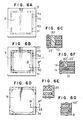
- FIG. 6A to 6E A fifth embodiment of the present invention will now be described with reference to Figs. 6A to 6E.
- holes are made in the connecting portions 4a and 4b of the multilayer body 20 by a drill so as to separate the product portions 2 from the peripheral portions 3, and an insulating resin is filled into and set in the connecting portions 4a and 4b before the external form of the multilayer body 20 is cut out.
- the connecting portions 4a and 4b are drilled and removed to form holes 30 and 31.
- Insulating resin 33 and 34 is then filled in the holes 30 and 31, respectively, as shown in Fig.6B.
- Fig. 6C is a cross-section taken along the line G - G ⁇ in Fig. 6B.
- the multilayer printed-wiring board 9 is cut out by cutting the multilayer body 20 along the two-dot dashed line 11 shown in Fig. 6B. At this time, since the cutting line passes through the holes 30 and 31, parts 35 and 36 of the insulating resin 33 and 34 filling the holes 30 and 31 remain on the edges of the multilayer printed-wiring board.
- a sixth embodiment of the present invention will now be described with reference to Figs. 6F and 6G.
- a multilayer printed-wiring board of this embodiment has connecting portions 4a and 4b drilled and removed as those of the fifth embodiment. However, the connecting portions 4a and 4b are drilled halfway therethrough, whereas the holes 30 and 31 in the fifth embodiment are through-holes.
- Fig. 6F shows a manufacturing process which corresponds to that shown in Fig. 6C.
- a hole 30 ⁇ which corresponds to the hole 30 in Fig. 6C is not a through-hole. This is because the hole 30 ⁇ is drilled for the purpose of removing the connecting portion 4a of the copper core 1a, and this purpose is attained by drilling the connecting portion 4a halfway therethrough.
- the hole 30 ⁇ is filled with an insulating resin 33 ⁇ in the same manner as in the fifth embodiment.
- part 35 ⁇ of the insulating resin 33 ⁇ is left on the sides of the multilayer printed-wiring board 9, as shown in Fig. 6G.
- the copper cores of the multilayer printed-wiring board in the third to sixth embodiments are not exposed at the end surfaces thereof, thereby providing insulation of the end surfaces of the multilayer printed-wiring board. Further, since it is not necessary to cut the copper cores when cutting out the external form of the multilayer printed-wiring board, excellent machining is ensured.
- a seventh embodiment of the present invention will now be described with reference to Fig. 7.
- part of the holes of the multilayer body 20 which have been drilled according to the fifth or sixth embodiment is provided with pads such as those formed according to the second embodiment.
- the holes 30 and 31 formed on a side 40 of the multilayer printed-wiring board 9 are filled with the insulating resin according to the fifth embodiment.
- the holes 30 and 31 formed on a side 41 are provided with pads 38 and 39 according to the second embodiment.
- Each of the pads 39 is connected to the inner copper core 1a, while each of the pads 38 is connected to the copper core 1b.
- Fig. 8 is a plan view of a modified embodiment of the copper core 1.
- a copper core 1 employed in this embodiment differs from any of the aforementioned copper cores 1, 1a and 1b in that the peripheral portion 3 is provided with slits 17 lying around the slits 16.
- the distance between the center line of the slits 16 and the center line of the slits 17 is made to be substantially equal to the outer diameter of a cutter used when the external form of the board is cut out.
- the connecting portions formed between adjacent slits 16 are disposed so as not to align with the connecting portions between the slits 17.
- the volume of the copper to be cut when the external form of the multilayer printed-wiring board is cut out by the cutter can be decreased, thereby improving the machinability of the external form.
- both the slits 16 and 17 are separately filled with the insulating resin. This can reduce the area of the slits 16 or 17, and chipping of the resin or generation of voids which may occur when the insulating resin is filled can therefore be prevented.
- the copper core of this embodiment can be employed in the multilayer printed-wiring board in either of the first to seventh embodiments.
- each of the hard copper cores is already separated into product portion and non-product portion except for the connecting portions before they are stacked into a multilayer body, the working for cutting the product portion from the multilayer body is facilitated.
- Insulating material is filled between the product portion and the peripheral portion of the copper cores when they are stacked into a multilayer body. Therefore, a multilayer printed-wiring board which has an insulating layer at the periphery thereof is provided by simply cutting out the product portions.
- the connecting portions are drilled or grooved after the multilayer body has been formed and the insulating resin is filled and set in the drilled or grooved portions before the external form is cut out, the edges of the copper cores can be entirely covered by the insulating resin after cutting out the external form.
- the connecting portions are recessed inwardly when the external form of the multilayer body with the drilled connecting portions is cut out or when the external form of the multilayer body is cut out, the resultant multilayer printed-wiring board can be prevented from coming into contact with the frame of the casing when the former is packaged in the latter, although complete insulation therebetween is not provided.
- the connecting portions are formed in such a manner that those in one of the copper cores are not aligned with those in the other copper core, short-circuiting between the copper cores or insulation failure due to the burr or sagging of the coppers can be prevented.
- connecting portions are removed before the external form is cut out and the insulating material is filled in the removed connecting portions, it is not necessary to cut the copper cores when the external form is cut out, thereby making it possible to effect a good machining.
Landscapes
- Engineering & Computer Science (AREA)
- Manufacturing & Machinery (AREA)
- Microelectronics & Electronic Packaging (AREA)
- Production Of Multi-Layered Print Wiring Board (AREA)
- Laminated Bodies (AREA)
Applications Claiming Priority (4)
| Application Number | Priority Date | Filing Date | Title |
|---|---|---|---|
| JP245237/86 | 1986-10-17 | ||
| JP61245237A JPS63100798A (ja) | 1986-10-17 | 1986-10-17 | 多層プリント基板の製造方法 |
| JP86829/87 | 1987-04-10 | ||
| JP62086829A JPS63253694A (ja) | 1987-04-10 | 1987-04-10 | 多層プリント基板の製造方法 |
Publications (2)
| Publication Number | Publication Date |
|---|---|
| EP0264105A2 true EP0264105A2 (de) | 1988-04-20 |
| EP0264105A3 EP0264105A3 (de) | 1988-07-27 |
Family
ID=26427910
Family Applications (1)
| Application Number | Title | Priority Date | Filing Date |
|---|---|---|---|
| EP87114945A Withdrawn EP0264105A3 (de) | 1986-10-17 | 1987-10-13 | Verfahren zur Herstellung einer mehrschichtigen Leiterplatte mit metallischem Kern |
Country Status (3)
| Country | Link |
|---|---|
| EP (1) | EP0264105A3 (de) |
| KR (1) | KR900005314B1 (de) |
| CN (1) | CN1007205B (de) |
Cited By (5)
| Publication number | Priority date | Publication date | Assignee | Title |
|---|---|---|---|---|
| DE3823469A1 (de) * | 1988-07-11 | 1990-01-18 | Bodenseewerk Geraetetech | Filteranordnung |
| EP0365755A1 (de) * | 1988-10-11 | 1990-05-02 | International Business Machines Corporation | Schaltungsteil unter Verwendung von mehrschichtigen gedruckten Leiterplatten und Verfahren zu dessen Herstellung |
| WO2004004432A1 (en) * | 2002-06-27 | 2004-01-08 | Ppg Industries Ohio, Inc. | Single or multi-layer printed circuit board with recessed or extended breakaway tabs and method of manufacture thereof |
| US6844504B2 (en) | 2002-06-27 | 2005-01-18 | Ppg Industries Ohio, Inc. | Single or multi-layer printed circuit board with recessed or extended breakaway tabs and method of manufacture thereof |
| US7485812B2 (en) * | 2002-06-27 | 2009-02-03 | Ppg Industries Ohio, Inc. | Single or multi-layer printed circuit board with improved via design |
Families Citing this family (6)
| Publication number | Priority date | Publication date | Assignee | Title |
|---|---|---|---|---|
| USRE45637E1 (en) | 2005-08-29 | 2015-07-28 | Stablcor Technology, Inc. | Processes for manufacturing printed wiring boards |
| CN102510665A (zh) * | 2011-10-20 | 2012-06-20 | 深圳市五株电路板有限公司 | 电路板加工方法 |
| US9332632B2 (en) | 2014-08-20 | 2016-05-03 | Stablcor Technology, Inc. | Graphene-based thermal management cores and systems and methods for constructing printed wiring boards |
| TWI672982B (zh) * | 2016-03-22 | 2019-09-21 | 慧榮科技股份有限公司 | 印刷電路板組裝物 |
| CN106132080A (zh) * | 2016-08-30 | 2016-11-16 | 江门全合精密电子有限公司 | 一种具有边绝缘结构的电银板及其制作方法 |
| CN107484340A (zh) * | 2017-08-04 | 2017-12-15 | 郑州云海信息技术有限公司 | 一种防毛边pcb板及加工方法 |
Family Cites Families (2)
| Publication number | Priority date | Publication date | Assignee | Title |
|---|---|---|---|---|
| DE2223892A1 (de) * | 1971-05-18 | 1973-01-11 | Maria Antonietta Brandi | Verfahren zum herstellen von elektrischen stromleiterplatten |
| US3860740A (en) * | 1972-03-14 | 1975-01-14 | David Vaughan Watkins | Encapsulated components |
-
1987
- 1987-10-13 EP EP87114945A patent/EP0264105A3/de not_active Withdrawn
- 1987-10-14 KR KR1019870011418A patent/KR900005314B1/ko not_active Expired
- 1987-10-16 CN CN 87107023 patent/CN1007205B/zh not_active Expired
Cited By (9)
| Publication number | Priority date | Publication date | Assignee | Title |
|---|---|---|---|---|
| DE3823469A1 (de) * | 1988-07-11 | 1990-01-18 | Bodenseewerk Geraetetech | Filteranordnung |
| US4945323A (en) * | 1988-07-11 | 1990-07-31 | Bruno Gerstenberg | Filter arrangement |
| EP0365755A1 (de) * | 1988-10-11 | 1990-05-02 | International Business Machines Corporation | Schaltungsteil unter Verwendung von mehrschichtigen gedruckten Leiterplatten und Verfahren zu dessen Herstellung |
| WO2004004432A1 (en) * | 2002-06-27 | 2004-01-08 | Ppg Industries Ohio, Inc. | Single or multi-layer printed circuit board with recessed or extended breakaway tabs and method of manufacture thereof |
| US6844504B2 (en) | 2002-06-27 | 2005-01-18 | Ppg Industries Ohio, Inc. | Single or multi-layer printed circuit board with recessed or extended breakaway tabs and method of manufacture thereof |
| US7002081B2 (en) | 2002-06-27 | 2006-02-21 | Ppg Industries Ohio, Inc. | Single or multi-layer printed circuit board with recessed or extended breakaway tabs and method of manufacture thereof |
| KR100711334B1 (ko) * | 2002-06-27 | 2007-04-27 | 피피지 인더스트리즈 오하이오 인코포레이티드 | 회로 기판 |
| US7485812B2 (en) * | 2002-06-27 | 2009-02-03 | Ppg Industries Ohio, Inc. | Single or multi-layer printed circuit board with improved via design |
| CN1672475B (zh) * | 2002-06-27 | 2011-11-23 | Ppg工业俄亥俄公司 | 有凹入或伸长分离接头片的单层或多层印刷电路板及其制造方法 |
Also Published As
| Publication number | Publication date |
|---|---|
| CN1007205B (zh) | 1990-03-14 |
| EP0264105A3 (de) | 1988-07-27 |
| CN87107023A (zh) | 1988-04-27 |
| KR900005314B1 (ko) | 1990-07-27 |
Similar Documents
| Publication | Publication Date | Title |
|---|---|---|
| US7345888B2 (en) | Component built-in wiring board and manufacturing method of component built-in wiring board | |
| US5047279A (en) | Multilayer printed circuit board | |
| US4338149A (en) | Process for making circuit boards having rigid and flexible areas | |
| US4872934A (en) | Method of producing hybrid multi-layered circuit substrate | |
| EP0264105A2 (de) | Verfahren zur Herstellung einer mehrschichtigen Leiterplatte mit metallischem Kern | |
| JPH0728134B2 (ja) | 導電性回路部材及びその製造方法 | |
| KR100349119B1 (ko) | 인쇄회로기판 및 그 제조방법 | |
| EP1460889A2 (de) | Kunststoffgehäuse mit hoher Wärmeabfuhr und Verfahren zu dessen Herstellung | |
| US6745463B1 (en) | Manufacturing method of rigid flexible printed circuit board | |
| JP2003133734A (ja) | ケーブル部を有するフレキシブルプリント基板 | |
| JP2562373B2 (ja) | 多層回路基板の層間導通構造の形成法 | |
| TWI295912B (en) | Method for manufacturing a substrate embedded with an electronic component and device from the same | |
| KR20050072678A (ko) | 다층 배선 기판 및 이의 제조 방법 | |
| JPS63100798A (ja) | 多層プリント基板の製造方法 | |
| JP2003046249A (ja) | 積層配線板およびその製造方法 | |
| JPH08307053A (ja) | 金属コアプリント配線板の製造方法 | |
| JPS60257585A (ja) | プリント配線基板およびその製法 | |
| JP2768655B2 (ja) | チップ部品の製造方法 | |
| JPH0786752A (ja) | 電子部品搭載用基板 | |
| JP2025099076A (ja) | 配線基板及び配線基板の製造方法 | |
| JP2005026318A (ja) | 配線基板の製造方法および配線基板素材 | |
| JPS59219995A (ja) | 多層印刷配線板の製造方法 | |
| JP2026010498A (ja) | 部品内蔵配線板及び部品内蔵配線板の製造方法 | |
| JP2021119590A (ja) | 印刷配線板及び印刷配線板の製造方法 | |
| JPH0316297A (ja) | 多層プリント配線板の製造方法 |
Legal Events
| Date | Code | Title | Description |
|---|---|---|---|
| PUAI | Public reference made under article 153(3) epc to a published international application that has entered the european phase |
Free format text: ORIGINAL CODE: 0009012 |
|
| AK | Designated contracting states |
Kind code of ref document: A2 Designated state(s): DE FR GB |
|
| PUAL | Search report despatched |
Free format text: ORIGINAL CODE: 0009013 |
|
| AK | Designated contracting states |
Kind code of ref document: A3 Designated state(s): DE FR GB |
|
| 17P | Request for examination filed |
Effective date: 19880729 |
|
| 17Q | First examination report despatched |
Effective date: 19900425 |
|
| STAA | Information on the status of an ep patent application or granted ep patent |
Free format text: STATUS: THE APPLICATION HAS BEEN WITHDRAWN |
|
| 18W | Application withdrawn |
Withdrawal date: 19900824 |
|
| R18W | Application withdrawn (corrected) |
Effective date: 19900824 |
|
| RIN1 | Information on inventor provided before grant (corrected) |
Inventor name: IMAI, TSUTOMU Inventor name: IMAHASHI, FUMIO Inventor name: KAWAGUCHI, MASAMI Inventor name: SENGOKU, NORIO Inventor name: SHIRASAWA, HISATO |