EP0264029A2 - Stuhl - Google Patents
Stuhl Download PDFInfo
- Publication number
- EP0264029A2 EP0264029A2 EP87114333A EP87114333A EP0264029A2 EP 0264029 A2 EP0264029 A2 EP 0264029A2 EP 87114333 A EP87114333 A EP 87114333A EP 87114333 A EP87114333 A EP 87114333A EP 0264029 A2 EP0264029 A2 EP 0264029A2
- Authority
- EP
- European Patent Office
- Prior art keywords
- backrest
- cradle
- chair
- chair according
- supported
- Prior art date
- Legal status (The legal status is an assumption and is not a legal conclusion. Google has not performed a legal analysis and makes no representation as to the accuracy of the status listed.)
- Granted
Links
Images


Classifications
-
- A—HUMAN NECESSITIES
- A47—FURNITURE; DOMESTIC ARTICLES OR APPLIANCES; COFFEE MILLS; SPICE MILLS; SUCTION CLEANERS IN GENERAL
- A47C—CHAIRS; SOFAS; BEDS
- A47C1/00—Chairs adapted for special purposes
- A47C1/02—Reclining or easy chairs
- A47C1/031—Reclining or easy chairs having coupled concurrently adjustable supporting parts
- A47C1/032—Reclining or easy chairs having coupled concurrently adjustable supporting parts the parts being movably-coupled seat and back-rest
- A47C1/03294—Reclining or easy chairs having coupled concurrently adjustable supporting parts the parts being movably-coupled seat and back-rest slidingly movable in the base frame, e.g. by rollers
-
- A—HUMAN NECESSITIES
- A47—FURNITURE; DOMESTIC ARTICLES OR APPLIANCES; COFFEE MILLS; SPICE MILLS; SUCTION CLEANERS IN GENERAL
- A47C—CHAIRS; SOFAS; BEDS
- A47C1/00—Chairs adapted for special purposes
- A47C1/02—Reclining or easy chairs
- A47C1/031—Reclining or easy chairs having coupled concurrently adjustable supporting parts
- A47C1/032—Reclining or easy chairs having coupled concurrently adjustable supporting parts the parts being movably-coupled seat and back-rest
- A47C1/03255—Reclining or easy chairs having coupled concurrently adjustable supporting parts the parts being movably-coupled seat and back-rest with a central column, e.g. rocking office chairs
-
- A—HUMAN NECESSITIES
- A47—FURNITURE; DOMESTIC ARTICLES OR APPLIANCES; COFFEE MILLS; SPICE MILLS; SUCTION CLEANERS IN GENERAL
- A47C—CHAIRS; SOFAS; BEDS
- A47C1/00—Chairs adapted for special purposes
- A47C1/02—Reclining or easy chairs
- A47C1/031—Reclining or easy chairs having coupled concurrently adjustable supporting parts
- A47C1/032—Reclining or easy chairs having coupled concurrently adjustable supporting parts the parts being movably-coupled seat and back-rest
- A47C1/03261—Reclining or easy chairs having coupled concurrently adjustable supporting parts the parts being movably-coupled seat and back-rest characterised by elastic means
- A47C1/03283—Reclining or easy chairs having coupled concurrently adjustable supporting parts the parts being movably-coupled seat and back-rest characterised by elastic means with fluid springs
-
- A—HUMAN NECESSITIES
- A47—FURNITURE; DOMESTIC ARTICLES OR APPLIANCES; COFFEE MILLS; SPICE MILLS; SUCTION CLEANERS IN GENERAL
- A47C—CHAIRS; SOFAS; BEDS
- A47C31/00—Details or accessories for chairs, beds, or the like, not provided for in other groups of this subclass, e.g. upholstery fasteners, mattress protectors, stretching devices for mattress nets
- A47C31/12—Means, e.g. measuring means, for adapting chairs, beds or mattresses to the shape or weight of persons
- A47C31/126—Means, e.g. measuring means, for adapting chairs, beds or mattresses to the shape or weight of persons for chairs
Definitions
- the invention relates to a chair, the chair frame is equipped with a seat part and a backrest part and is supported from a support part forming part of the chair foot, which is provided with a cantilevered support arm.
- Chairs of this type are known in various designs.
- the seat part In order to increase the seating comfort, it is known to design the seat part to be pivotable relative to the supporting part, a counterforce being exerted with a spring element to support the body weight of the seated person. If the seating comfort is to be increased further, in particular in that a "relax" position can be assumed by the seated person, it is also known to design the back part to be pivotable relative to the seat part. In this case, too, it is necessary to generate a counterforce to the forces exerted by the seated person on this part by means of one or more correspondingly arranged spring elements.
- the invention relates to chairs in which at least the seat part is pivotally supported with respect to the supporting part, and it is the object of the invention to further develop a chair of the type described in the introduction in such a way that the forces to be exerted by the spring element or the spring elements are kept small and thus smaller spring elements can be used at a correspondingly lower cost. Another object is to keep the volume of the chair frame lying under the seat part small, thereby avoiding the bulky appearance of known chairs.
- pairs of straps are pivotally articulated on the support arm of the support part with straps arranged on the knee side and backrest side, which form a parallelogram suspension for a cradle, on which the seat part and the backrest part are supported. Because the forces exerted on the seat part and the backrest part are at least partially balanced by the cradle, it was achieved that only a part of the forces occurring has to be absorbed by the spring element or the spring elements.
- Fig. 1 denotes a support part of a base frame (not shown) of a chair, to which a support arm 2 extending slightly obliquely against the knee side of the chair is attached.
- a support arm 2 extending slightly obliquely against the knee side of the chair is attached.
- two swivel joints 3, 4 are arranged, to which a pair of plates with plates 5, 6 is articulated.
- the tabs 5, 6 are pivotally connected to a cradle 9 via further swivel joints 7, 8.
- the chair has a seat part 10 and a backrest part 11. These two parts can either be rigid or articulated together.
- the seat part 10 is fastened to the cradle 9 in the vicinity of the knee-side bracket 6.
- the backrest part is supported on the cradle 9 via a linkage 12.
- the linkage 12 is composed of several parts, namely an extension arm 15, which forms part of the backrest-side tab 5, a push rod 16, which is connected to the extension arm 15 by means of a swivel joint 17, a slide 20, to which the push rod 16 is connected a hinge 18 and which is guided on the cradle 9, and a backrest strut 21 which is rotatably supported on the one hand by means of a fixed connection 19 on the backrest part 11 and on the other hand is rotatably supported on the slide 20 via the hinge 18.
- a spring element 25 is mounted on the cradle 9, one end 26 of which is connected to the slide 20 and the other end 27 is fastened to the cradle 9.
- the spring element 25 can be a compression spring or a gas spring.
- one end 26 is a piston rod supported on the slide 20 and the other end 27 is a cylinder attached to the cradle. Since the spring element 25 only moves parallel to the cradle 9, the ends 26, 27 can be firmly connected to the cradle.
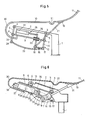
- Fig. 2 the so-called "relax" position of the chair is shown.
- the force exerted on the slide 20 by the backrest part 11 via the backrest strut 21 causes the slide 20 on the cradle 9 to act against the force of the spring element 25 moved towards the knee side of the chair.
- the straps 5, 6 of the pair of straps are pivoted against the knee side of the chair.
- the cradle 9, which is also articulated on the tabs 5, 6, is also displaced in the direction of the knee side of the chair, but this path is smaller since the slide 20 is displaced by the extension arm 15.
- the difference between these two displacement paths is the path by which the spring element 25 is compressed and thereby exerts a counterforce.
- the spring element 25 can be dimensioned correspondingly smaller.
- the two parts 10, 11 are a single fiber-reinforced plastic shell.
- This has a bending joint 30 on the knee side, which can be provided with a progressive spring force, for example.
- a further flexible joint 31 is provided between the seat part 10 and the backrest part 11, the spring characteristic of which can also be selected accordingly. If necessary, the flexible joint 31 can also be designed with more than one bend.
- Another bending joint 32 can be provided in the backrest part 11.
- a plastic shell can be replaced by a shell construction made of metal or it can be hinged seat and backrest parts be used.
- the knee-side bending joint 30 can be replaced by a swivel joint, for example by a torsion spring element, as can the bending joint 31.
- the torsion spring other springs can also be used, but problems with regard to the space conditions can arise here.
- the support arm 2 of the support part 1 is designed as a double arm. For this reason, two pairs of plates with plates 5, 6 are also arranged.
- the cradle 9 is in the form of a hollow cylinder, e.g. a square tube. This has a slot 35 on the underside, in which the slide 20 consisting of plates 36, 37 is held together by a connecting bolt (not shown).
- the piston rod 26 is attached to the slide 20 and the cylinder 27 of the spring element 25 is attached to the knee-side end of the cradle 9.
- An actuating device 38 serves to release or block the spring element 25. From FIG. 4 it can be seen that two backrest struts 21 are articulated on the swivel joint 18.
- a fastening plate 40 is provided on the knee side for fastening the parts 10, 11 designed as a plastic shell.
- the tab 6, like the tab 5, is formed with an extension arm 34.
- a swivel joint 28 is provided at the free end of the extension arm 34.
- the swivel joint 28 and the swivel joint 17 of the extension arm 15 are connected to a connecting bracket 33.
- the extension arms 15 and 34 and the connecting plate 33 thus form a parallelogram arrangement with the cradle 9, which is parallel to the parallelogram arrangement of the plates 5 and 6 and the cradle 9.
- the support arm 2 of the support frame 1 is designed as a double arm (not visible). Accordingly, two pairs of tabs with tabs 5, 6 are arranged. Between the arms of the double arm of the support arm 2, the cradle 9 is in the form of a hollow cylinder, e.g. a square tube. This has a slot 35 on the underside, in which the slide 20 consisting of plates 36, 37 is held together by a connecting bolt (not shown).
- the piston rod 26 is attached to the slide 20 and the cylinder 27 of the spring element 25 is attached to the knee-side end of the cradle 9.
- An actuating device 38 serves to release or block the spring element 18.
- the tabs 5, 6 with their extension arms 16, 34 form two-armed levers, the bearing point between the arms of which forms the joints 7, 8 connected to the cradle 9.
- the connecting strap 33 connected via the joints 17, 28 to the two-armed levers 5, 15 and 6, 34 is shown in broken lines in FIG. 6 in order to make the drawing clearer.
- the connecting tab 33 is expediently opposite arched, that is, concave against the seat part 10.
- the connecting tab 33 can be punched out of a strip material and provided with a bore at its ends.
- the chair frame described has the advantage that some of the forces exerted by a seated person are inherent, i.e. be balanced by a weighing device, which is formed by the pairs of plates 5, 6 and the cradle 9. As a result, the spring element 25 can be designed smaller, so that it can be accommodated in the cradle 9 itself. Because of this balancing of the forces, there is no need to adjust the spring element in relation to the respective weight of the seated person. If this person sits on the chair without leaning, practically the entire weight is balanced by this device. Only at the transition to the "relax" position is part of this weight absorbed by the spring element 25.
Landscapes
- Health & Medical Sciences (AREA)
- Dentistry (AREA)
- General Health & Medical Sciences (AREA)
- Chairs Characterized By Structure (AREA)
- Chair Legs, Seat Parts, And Backrests (AREA)
- Chairs For Special Purposes, Such As Reclining Chairs (AREA)
- Acyclic And Carbocyclic Compounds In Medicinal Compositions (AREA)
- Finger-Pressure Massage (AREA)
- Pharmaceuticals Containing Other Organic And Inorganic Compounds (AREA)
- Pyridine Compounds (AREA)
- Plural Heterocyclic Compounds (AREA)
Abstract
Description
- Die Erfindung betrifft einen Stuhl, dessen Stuhlgestell mit einem Sitzteil und einem Rückenlehnenteil ausgerüstet und aus einem, einen Teil des Stuhlfusses bildenden Tragteil abgestützt ist, welcher mit einem auskragenden Tragarm versehen ist.
- Stühle dieser Art sind in verschiedenen Ausführungen bekannt. Um den Sitzkomfort zu erhöhen, ist es bekannt, den Sitzteil gegenüber dem Tragteil schwenkbar auszubilden, wobei mit einem Federelement eine Gegenkraft zum Abstützen des Körpergewichtes der sitzenden Person ausgeübt wird. Soll der Sitzkomfort weiter erhöht werden, insbesondere dadurch, dass der von der sitzenden Person eine "Relax"-Stellung eingenommen werden kann, ist es auch bekannt, den Rückenteil gegenüber dem Sitzteil schwenkbar auszubilden. Auch in diesem Fall ist es erforderlich, den von der sitzenden Person auf diesen Teil ausgeübten Kräften durch ein oder mehr entsprechend angeordnete Federelemente eine Gegenkraft zu erzeugen.
- Die von der sitzenden Person auf den Sitzteil und den Rückenlehnenteil ausgeübten Kräfte, welch auf den Tragteil übergeleitet werden, sind beträchtlich. Bei Stühlen mit einem schwenkbaren Sitzteil und/oder einem schwenkbaren Rückenteil ist es erforderlich, diese beiden Teile zur Gewährleistung ihrer Beweglichkeit auf einem Stuhlgestell abzustützen. Unter dem Stuhlgestell werden hier Teile wie Laschen, Hebel und Federelemente verstanden, mit deren Hilfe der Sitzteil- und der Rückenlehnenteil auf dem Tragteil abgestützt werden. Da aber das Stuhlgestell auf möglichst kleinem Platz untergebracht werden muss, haben diese Teile wegen ihrer Art der Anordnung teilweise wesentlich grössere Kräfte als nur das Körpergewicht sitzender Personen aufzunehmen, insbesondere müssen die Federelemente für zum Teil recht grosse Kräfte ausgelegt werden. Sie beeinflussen damit den Herstellungsaufwand in ungünstigem Sinn.
- Die Erfindung bezieht sich auf Stühle, bei welchen mindestens der Stitzteil gegenüber dem Tragteil schwenkbar abgestützt ist, und es liegt der Erfindung die Aufgabe zugrunde, einen Stuhl der eingangs beschriebenen Art so weiter auszugestalten, dass die von dem Federelement bzw. den Federelementen auszuübenden Kräfte kleingehalten und dadurch kleinere Federelemente mit entsprchend geringeren Kosten verwendet werden können. Eine weitere Aufgabe besteht darin, das Volumen des unter dem Stitzteil liegenden Stuhlgestells klein zu halten, wodurch das bei bekannten Stühlen klobige Aussehen vermieden wird.
- Diese Aufgabe wird dadurch gelöst, dass am Tragarm des Tragteiles Laschenpaare mit knieseitig und rückenlehnenseitig angeordnete Laschen schwenkbar angelenkt sind, welche eine Parallelogramm-Aufhängung für eine Wiege bilden, an welcher der Sitzteil und der Rückenlehnenteil abgestützt sind. Dadurch, dass die auf den Sitzteil- und den Rückenlehnenteil ausgeübten Kräfte mindestens teilweise durch die Wiege ausbalanciert werden, wurde erreicht, dass nur ein Teil der auftretenden Kräfte von dem Federelement bzw. den Federelementen aufgenommen werden muss.
- Ein Ausführungsbeispiel der Erfindung ist in der Zeichnung dargestellt und nachfolgend beschrieben. Es zeigen:
- Fig. 1 das kinematische Ersatzbild eines erfindungsgemässen Stuhles, bei welchem die Rückenlehne nicht belastet und dadurch der Sitzteil nicht nach hinten abwärts geschwenkt wird,
- Fig. 2 das kinematische Ersatzbild des Stuhles nach Fig. 1, bei welchem die Rückenlehne belastet und dadurch der Sitzteil nach hinten abwärts geschwenkt wird (sogenannte "Relax"-Stellung),
- Fig. 3 eine schematische Darstellung eines Vertikalschnittes einer Ausführung des Stuhls gemäss dem kinematischen Ersatzbild nach Fig. 1 und 2,
- Fig. 4 eine Draufsicht auf den Stuhl nach Fig. 3 mit entferntem Sitzteil und Rückenlehnenteil,
- Fig. 5 das kinematische Ersatzbild eines Stuhles mit neigbarer Sitzpartie in der Arbeitsstellung, d.h. bei nicht nach hinten abwärts geschwenkter Rückenlehne, und
- Fig. 6 eine schematische Darstellung eines Vertikalschnittes einer Ausführungsfrom des Stuhls gemäss dem kinematischen Ersatzbild nach Fig. 1.
- In Fig. 1 ist mit 1 ein Tragteil eines Fussgestells (nicht dargestellt) eines Stuhls bezeichnet, an welchem ein leicht schräg gegen die Knieseite des Stuhls sich erstreckender Tragarm 2 befestigt ist. An dem Tragarm 2 sind zwei Drehgelenke 3, 4 angeordnet, an welchen ein Laschenpaar mit Laschen 5, 6 angelenkt ist. Die Laschen 5, 6 sind über weitere Drehgelenke 7, 8 mit einer Wiege 9 schwenkbar verbunden.
- Der Stuhl weist einen Sitzteil 10 und einen Rückenlehnenteil 11 auf. Diese beiden Teile können entweder starr oder gelenkig mtieinander verbunden sein. Der Sitzteil 10 ist in der Nähe der knieseitigen Lasche 6 an der Wiege 9 befestigt. Der Rückenlehnenteil ist über ein Gestänge 12 an der Wiege 9 abgestützt.
- Das Gestänge 12 setzt sich aus mehreren Teilen zusammen, nämlich einem Verlängerungsarm 15, welcher einen Teil der rückenlehnenseitigen Lasche 5 bildet, einer Schubstange 16, welche mittels eines Drehgelenkes 17 mit dem Verlängerungsarm 15 verbunden ist, einem Schieber 20, an welchem die Schubstange 16 mittels eines Drehgelenkes 18 angelenkt und welcher an der Wiege 9 verschiebbar geführt ist, und einer Rückenlehnenstrebe 21, die einerseits mittels einer festen Verbindung 19 an dem Rückenlehnenteil 11 drehbar abgestützt und andererseits über das Drehgelenk 18 am Schieber 20 drehbar abgestützt ist. Es wäre jedoch auch möglich, die Rückenlehnenstrebe 21 am Drehgelenk 17 des Verlängerungsarmes 15 abzustützen.
- Auf der Wiege 9 ist ein Federelement 25 gelagert, von welchem das eine Ende 26 mit dem Schieber 20 verbunden und das andere Ende 27 an der Wiege 9 befestigt ist.
- Das Federelement 25 kann eine Druckfeder oder eine Gasfeder sein. Im Falle einer Gasfeder ist das eine Ende 26 eine am Schieber 20 abgestützte Kolbenstange und das andere Ende 27 ein an der Wiege befestigter Zylinder. Da das Federelement 25 sich nur parallel zur Wiege 9 verschiebt, können die Enden 26, 27 fest mit der Wiege verbunden werden.
- In Fig. 2 ist die sogenannte "Relax"-Stellung des Stuhls dargestellt. Durch die vom Rückenlehnenteil 11 über die Rückenlehnenstrebe 21 auf den Schieber 20 ausgeübte Kraft wird der Schieber 20 auf der Wiege 9 gegen die Kraft des Federelementes 25 in Richtung der Knieseite des Stuhls verschoben. Gleichzeitig werden die Laschen 5, 6 des Laschenpaares gegen die Knieseite des Stuhls geschwenkt. Die Wiege 9, welche ebenfalls an den Laschen 5, 6 angelenkt ist, wird ebenfalls in Richtung der Knieseite des Stuhls verschoben, doch ist dieser Weg kleiner, da der Schieber 20 durch den Verlängerungsarm 15 verschoben wird. Die Differenz dieser beiden Verschiebungswege ist der Weg, um welchen das Federelement 25 zusammengedrückt wird und dadurch eine Gegenkraft ausübt. Es ist nun aus Fig. 1 und 2 ohne Schwierigkeit erkennbar, dass das Gewicht einer auf dem Stuhl sitzenden Person nich gesamthaft von dem Federelement 25 aufgenommen werden muss, sondern durch die Schwenkbewegung der Laschen 5, 6 und der Wiege 9 mindestens teilweise ausbalanciert werden kann. Dadurch wird erreicht, dass das Federelement 25 entsprechend kleiner dimensioniert werden kann.
- Für das Funktionieren der Balancier-Wirkung der parallelogrammartig aufgehängten Wiege 9 ist es unwesentlich, wie im einzelnen der Sitzteil 10 und der Rückenlehnenteil 11 ausgebildet sind. In Fig. 1 und 2 sind die beiden Teile 10, 11 eine einzige, durch Fasern verstärkte Kunststoffschale. Diese weist knieseitig ein Biegegelenk 30 auf, das beispielsweise mit einer progressiven Federkraft versehen werden kann. Zwischen dem Sitzteil 10 und dem Rückenlehnenteil 11 ist ein Weiteres Biegegelenk 31 vorgesehen, dessen Federcharakteristik ebenfalls entsprechend gewählt werden kann. Falls es erforderlich ist, kann auch das Biegegelenk 31 mit mehr als einer Biegung ausgebildet sein. Ein weiteres Biegegelenk 32 kann im Rückenlehnenteil 11 vorgesehen werden. Durch die Ausbildung dieser Biegegelenke kann der Stuhl mit einer beliebigen Schwenkcharakteristik ausgebildet werden.
- Anstelle einer Kunststoffschale können auch andere Ausführungen mit dem beschriebenen Gestänge 12 kombiniert werden. So kann eine Kunststoffschale durch eine Schalenkonstruktion aus Metall ersetzt oder es können mit Gelenken versehene Sitz- und Rückenlehnenteile verwendet werden. In diesem Fall kann das knieseitige Biegegelenk 30 durch ein Drehgelenk, beispielsweise durch ein Torsionsfederelement ersetzt werden, ebenso das Biegegelenk 31. Anstelle der Torsionsfeder können auch andere Federn verwendet werden, jedoch können hierbei Probleme bezüglich der Platzverhältnisse auftreten.
- In Fig. 3 und 4 ist eine Ausführungsform des beschriebenen Stuhlgestelles dargestellt. Die Bezugszeichen haben dieselbe Bedeutung wie in Fig. 1 und 2 und werden deshalb nicht nochmals erläutert. Aus Fig. 4 ist ersichtlich, dass der Tragarm 2 des Tragteils 1 als Doppelarm ausgebildet sind. Deshalb werden auch zwei Laschenpaare mit Laschen 5, 6 angeordnet. Zwischen den Teilarmen des Tragarms 2 ist die Wiege 9 in Form eines Hohlzylinders, z.B. eines Vierkantrohres, ausgebildet. Dieses weist auf der Unterseite einen Schlitz 35 auf, in welchem der aus Platten 36, 37 bestehende Schieber 20 durch einen Verbindungsbolzen (nicht dargestellt) zusammengehalten ist. Auf dem Schieber 20 ist die Kolbenstange 26 und am knieseitigen Ende der Wiege 9 der Zylinder 27 des Federelementes 25 befestigt. Eine Betätigungsvorrichtung 38 dient der Freigabe bzw. dem Blockieren des Federelementes 25. Aus der Fig. 4 ist ersichtlich, dass am Drehgelenk 18 zwei Rückenlehnenstreben 21 angelenkt sind. Für die Befestigung der als Kunststoffschale ausgebildeten Teile 10, 11 ist knieseitig eine Befestigungsplatte 40 vorgesehen.
- In der Fig. 5 und 6 dargestellten Ausführungsform weisen gleiche Bezugszeichen gleiche Bedeutung wie in Fig. 1 - 4 auf.
- Um die Genauigkeit für die Herstellung der Parallelogramm-Aufhängung verringern und trotzdem gewährleisten zu können, dass die Parallelogramm-Aufhängung spielfrei und klemmfrei funktionieren kann, wird eine weitere Parallelogramm-Aufhängung vorgesehen.
- Hierzu wird die Lasche 6 gleich wie die Lasche 5 mit einem Verlängerungsarm 34 ausgebildet. An dem freien Ende des Verlängerungsarmes 34 wird ein Drehgelenk 28 vorgesehen. Das Drehgelenk 28 und das Drehgelenk 17 des Verlängerungsarmes 15 wird mit einer Verbindungslasche 33 verbunden. Die Verlängerungsarme 15 und 34 sowie die Verbindungslasche 33 bilden somit zur Wiege 9 eine Parallelogramm-Anordnung, die zu der Parallelogramm-Anordnung der Laschen 5 und 6 sowie der Wiege 9 parallel liegt.
- In Fig. 6 ist eine platzsparende Ausführungsform des nach Fig. 5 beschriebenen Stuhlgestelles dargestellt. Die Bezugszeichen haben dieselbe Bedeutung wie in Fig. 6, weshalb sie nur soweit erläutert werden, wie dies für das Verständnis der Funktion des Stuhles erforderlich est. Der Tragarm 2 des Traggestells 1 ist als Doppelarm (nicht sichtbar) ausgebildet. Dementsprechend werden auch zwei Laschenpaare mit Laschen 5, 6 angeordnet. Zwischen den Armen des Doppelarmes des Tragarms 2 ist die Wiege 9 in Form eines Hohlzylinders, z.B. eines Vierkantrohres, ausgebildet. Dieses weist auf der Unterseite einen Schlitz 35 auf, in welchem der aus Platten 36, 37 bestehende Schieber 20 durch einen Verbindungsbolzen (nicht dargestellt), zusammengehalten ist. Auf dem Schieber 20 ist die Kolbenstange 26 und am knieseitigen Ende der Wiege 9 der Zylinder 27 des Federelementes 25 befestigt. Eine Betätigungsvorrichtung 38 dient der Freigabe bzw. dem Blockieren des Federelementes 18.
- Die Laschen 5, 6 mit ihren Verlängerungsarmen 16, 34 bilden zweiarmige Hebel, deren zwischen den Armen liegende Lagerstelle die mit der Wiege 9 verbundenen Gelenke 7, 8 bilden.
- Die über die Gelenke 17, 28 mit den zweiarmigen Hebeln 5, 15 und 6, 34 verbundende Verbindungslasche 33 ist in Fig. 6 strichpunktiert dargestellt, um die Zeichnung übersichtlicher zu gestalten. Die Verbindungslasche 33 ist zweckmässig entgegengesetzt gewölbt, d.h. konkav gegen den Sitzteil 10 ausgebildet. Die Verbindungslasche 33 kann aus einem Bandmaterial gestanzt und an seinen Enden mit einer Bohrung versehen sein.
- Wesentlich ist weiter, dass die zweiarmigen Hebel 5, 15 und 6, 34, wie aus Fig. 6 ersichtlich ist, als Winkelhebel ausgebildet sind.
- Trotz der in Fig. 6 verwendeten Formabweichungen der zweiarmigen Hebel 5, 15 und 6, 34 als Winkelhebel und der konkav gegen den Sitzteil 10 gerichteten Verbindungslasche 32 bleibt die Funktion der Wiegevorrichtung dieselbe wie bei dem in dem erwähnten älteren Schutzrecht beschriebenen Stuhl.
- Das beschriebene Stuhlgestell weist den Vorteil auf, dass ein Teil der von einer sitzenden Person ausgeübten Kräfte in sich, d.h. durch eine Wiegevorrichtung, die durch die Laschenpaare 5, 6 und die Wiege 9 gebildet wird, ausbalanciert werden. Dadurch kann das Federelement 25 kleiner ausgelegt werden, so dass es in der Wiege 9 selbst untergebracht werden kann. Wegen dieser Ausbalancierung der Kräfte kann auf eine Einstellung des Federelementes in Bezug auf das jeweilige Gewicht der sitzenden Person verzichtet werden. Setzt sich diese Person ohne anzulehnen auf den Stuhl, wird praktisch das ganze Gewicht durch diese Vorrichtung ausbalanciert. Erst beim Uebergang in die "Relax"-Stellung wird ein Teil dieses Gewichtes durch das Federelement 25 aufgenommen.
Claims (11)
Priority Applications (1)
| Application Number | Priority Date | Filing Date | Title |
|---|---|---|---|
| AT87114333T ATE78139T1 (de) | 1986-10-14 | 1987-10-01 | Stuhl. |
Applications Claiming Priority (4)
| Application Number | Priority Date | Filing Date | Title |
|---|---|---|---|
| CH4124/86A CH672237A5 (en) | 1986-10-14 | 1986-10-14 | Relaxing chair |
| CH4124/86 | 1986-10-14 | ||
| CH2589/87 | 1987-07-08 | ||
| CH2589/87A CH674127A5 (en) | 1986-10-14 | 1987-07-08 | Relaxing chair |
Publications (3)
| Publication Number | Publication Date |
|---|---|
| EP0264029A2 true EP0264029A2 (de) | 1988-04-20 |
| EP0264029A3 EP0264029A3 (en) | 1988-07-06 |
| EP0264029B1 EP0264029B1 (de) | 1992-07-15 |
Family
ID=25690857
Family Applications (1)
| Application Number | Title | Priority Date | Filing Date |
|---|---|---|---|
| EP87114333A Expired - Lifetime EP0264029B1 (de) | 1986-10-14 | 1987-10-01 | Stuhl |
Country Status (14)
| Country | Link |
|---|---|
| US (1) | US4790598A (de) |
| EP (1) | EP0264029B1 (de) |
| JP (2) | JPS63102714A (de) |
| AT (1) | ATE78139T1 (de) |
| AU (1) | AU600310B2 (de) |
| BR (1) | BR8705450A (de) |
| CA (1) | CA1294524C (de) |
| CH (2) | CH672237A5 (de) |
| DE (1) | DE3780399D1 (de) |
| DK (1) | DK535887A (de) |
| FI (1) | FI87978C (de) |
| NO (1) | NO874262L (de) |
| PT (1) | PT85903B (de) |
| ZA (1) | ZA877507B (de) |
Cited By (3)
| Publication number | Priority date | Publication date | Assignee | Title |
|---|---|---|---|---|
| DE3821042A1 (de) * | 1988-06-22 | 1989-12-28 | Buerositzmoebelfabrik Friedric | Stuhl, insbesondere buerostuhl |
| WO1995026152A1 (de) * | 1994-03-25 | 1995-10-05 | Simon Desanta | Stuhl |
| WO1997003590A1 (de) * | 1995-07-20 | 1997-02-06 | Röder, Peter | Stuhl, insbesondere reihenstuhl |
Families Citing this family (18)
| Publication number | Priority date | Publication date | Assignee | Title |
|---|---|---|---|---|
| US5015032A (en) * | 1989-07-26 | 1991-05-14 | Felling Gerald J | Chaise lounge with adjustable canopy |
| ATE152333T1 (de) * | 1990-03-20 | 1997-05-15 | Gerald J Felling | Chaiselongue mit verstellbarer überdachung |
| DE9115439U1 (de) * | 1991-12-12 | 1992-05-07 | Pürner, Christoph, 8590 Marktredwitz | Aufhängevorrichtung für ein Sitz- oder Ruhemöbel |
| EP0763991A4 (de) * | 1994-06-10 | 2000-10-04 | Haworth Inc | Ergonomischer stuhl |
| US6191886B1 (en) * | 1998-08-24 | 2001-02-20 | Vutec Corp. | Video projection screen assembly |
| DE19916593C2 (de) * | 1999-04-13 | 2003-06-12 | Fast Ag Grenchen | Fluggastsitz |
| CA2482133C (en) * | 2004-09-14 | 2010-01-05 | Broda Enterprises Inc. | Glider chair with self-locking mechanism |
| US7802846B2 (en) * | 2007-03-19 | 2010-09-28 | Pierre Bellefleur | Reclining chair and chassis, frame and kit therefor |
| US20090315376A1 (en) * | 2008-06-19 | 2009-12-24 | Takuro Nishiwaki | Reclinable chair with adjustable parallel locking gas spring device |
| RU2518280C2 (ru) | 2008-12-12 | 2014-06-10 | Формвэй Фурнитуре Лимитед | Кресло и опорная структура |
| USD653591S1 (en) | 2010-12-08 | 2012-02-07 | Broda Enterprises, Inc. | Modular chair |
| US9084708B2 (en) | 2010-12-08 | 2015-07-21 | Broda Enterprises Inc. | Modular chair |
| DE202012002288U1 (de) | 2012-03-08 | 2012-05-11 | Walter Knoll Ag & Co. Kg | Funktionsstuhl |
| US9560917B2 (en) | 2014-11-26 | 2017-02-07 | Steelcase Inc. | Recline adjustment system for chair |
| US11259637B2 (en) | 2015-04-13 | 2022-03-01 | Steelcase Inc. | Seating arrangement |
| US10966527B2 (en) | 2017-06-09 | 2021-04-06 | Steelcase Inc. | Seating arrangement and method of construction |
| US10194750B2 (en) | 2015-04-13 | 2019-02-05 | Steelcase Inc. | Seating arrangement |
| MY206922A (en) | 2015-04-13 | 2025-01-17 | Steelcase Inc | Seating arrangement |
Family Cites Families (8)
| Publication number | Priority date | Publication date | Assignee | Title |
|---|---|---|---|---|
| US2615497A (en) * | 1949-05-26 | 1952-10-28 | Anton Lorenz | Reclining article of furniture |
| US2942647A (en) * | 1957-08-26 | 1960-06-28 | Ferro Stamping Co | Slideless seat support and adjusting device |
| US3765720A (en) * | 1971-07-02 | 1973-10-16 | Nissan Motor | Position adjustable support mechanism |
| FR2434599A1 (fr) * | 1978-08-30 | 1980-03-28 | Grosfillex Sarl | Siege pour gradins de stade |
| CH645795A5 (en) * | 1979-07-23 | 1984-10-31 | Drabert Soehne | Chair, in particular visual display unit chair |
| US4586749A (en) * | 1983-08-05 | 1986-05-06 | Takara Company, New York, Inc. | Barber/beauty chair |
| US4632450A (en) * | 1984-11-21 | 1986-12-30 | Cambridge Technologies, Inc. | Convertible wheelchair/litter |
| DE8614185U1 (de) * | 1986-05-26 | 1986-07-17 | Drabert Söhne GmbH & Co, 4950 Minden | Stuhl |
-
1986
- 1986-10-14 CH CH4124/86A patent/CH672237A5/de not_active IP Right Cessation
-
1987
- 1987-03-28 JP JP62075762A patent/JPS63102714A/ja active Pending
- 1987-07-08 CH CH2589/87A patent/CH674127A5/de not_active IP Right Cessation
- 1987-09-30 AU AU79241/87A patent/AU600310B2/en not_active Ceased
- 1987-09-30 CA CA000548281A patent/CA1294524C/en not_active Expired - Lifetime
- 1987-10-01 AT AT87114333T patent/ATE78139T1/de not_active IP Right Cessation
- 1987-10-01 DE DE8787114333T patent/DE3780399D1/de not_active Expired - Lifetime
- 1987-10-01 EP EP87114333A patent/EP0264029B1/de not_active Expired - Lifetime
- 1987-10-06 ZA ZA877507A patent/ZA877507B/xx unknown
- 1987-10-09 US US07/106,455 patent/US4790598A/en not_active Expired - Fee Related
- 1987-10-12 PT PT85903A patent/PT85903B/pt not_active IP Right Cessation
- 1987-10-13 FI FI874519A patent/FI87978C/fi not_active IP Right Cessation
- 1987-10-13 BR BR8705450A patent/BR8705450A/pt not_active IP Right Cessation
- 1987-10-13 DK DK535887A patent/DK535887A/da not_active Application Discontinuation
- 1987-10-13 NO NO874262A patent/NO874262L/no unknown
- 1987-10-14 JP JP62259450A patent/JPS63111811A/ja active Pending
Cited By (4)
| Publication number | Priority date | Publication date | Assignee | Title |
|---|---|---|---|---|
| DE3821042A1 (de) * | 1988-06-22 | 1989-12-28 | Buerositzmoebelfabrik Friedric | Stuhl, insbesondere buerostuhl |
| WO1995026152A1 (de) * | 1994-03-25 | 1995-10-05 | Simon Desanta | Stuhl |
| US5664835A (en) * | 1994-03-25 | 1997-09-09 | Peter Roeder | Chair |
| WO1997003590A1 (de) * | 1995-07-20 | 1997-02-06 | Röder, Peter | Stuhl, insbesondere reihenstuhl |
Also Published As
| Publication number | Publication date |
|---|---|
| FI87978B (fi) | 1992-12-15 |
| NO874262L (no) | 1988-04-15 |
| DE3780399D1 (de) | 1992-08-20 |
| PT85903A (pt) | 1988-11-30 |
| DK535887A (da) | 1988-04-15 |
| CA1294524C (en) | 1992-01-21 |
| AU600310B2 (en) | 1990-08-09 |
| PT85903B (pt) | 1993-07-30 |
| JPS63111811A (ja) | 1988-05-17 |
| EP0264029A3 (en) | 1988-07-06 |
| BR8705450A (pt) | 1988-05-24 |
| ZA877507B (en) | 1988-04-15 |
| CH672237A5 (en) | 1989-11-15 |
| US4790598A (en) | 1988-12-13 |
| NO874262D0 (no) | 1987-10-13 |
| FI874519A0 (fi) | 1987-10-13 |
| EP0264029B1 (de) | 1992-07-15 |
| FI87978C (fi) | 1993-03-25 |
| CH674127A5 (en) | 1990-05-15 |
| FI874519A7 (fi) | 1988-04-15 |
| DK535887D0 (da) | 1987-10-13 |
| ATE78139T1 (de) | 1992-08-15 |
| JPS63102714A (ja) | 1988-05-07 |
| AU7924187A (en) | 1988-04-21 |
Similar Documents
| Publication | Publication Date | Title |
|---|---|---|
| EP0264029A2 (de) | Stuhl | |
| EP0179933B1 (de) | Arbeitsstuhl, insbesondere Bürostuhl | |
| EP0247311B1 (de) | Stuhl | |
| CH636252A5 (de) | Ergonomischer stuhl. | |
| DE3741472A1 (de) | Stuhl | |
| CH662257A5 (de) | Arbeitsstuhl. | |
| DE3027311A1 (de) | Stuhl, insbesondere datensichtgeraete-stuhl | |
| EP0349762A2 (de) | Sitz, insbesondere für einen Flugbegleiter | |
| EP0250995A2 (de) | Stuhl, insbesondere Bürostuhl | |
| DE3033953C2 (de) | Stuhl, insbesondere für die Bedienung von Datensichtgeräten | |
| DE3817761A1 (de) | Stuhl, insbesondere arbeits- oder buerostuhl | |
| CH675817A5 (de) | ||
| DE102017209041A1 (de) | Stuhl, insbesondere Konferenz- oder Bürostuhl sowie Verfahren zur Herstellung eines Stuhls | |
| DE202005004880U1 (de) | Stuhl, insbesondere Bürostuhl | |
| EP1989961B1 (de) | Synchronmechanik für Bürostühle | |
| DE4219599C2 (de) | Synchronverstelleinrichtung für Bürostühle oder dergleichen | |
| EP0233974B1 (de) | Neigungsvorrichtung für Sitzmöbel | |
| DE3116459A1 (de) | Stuhl | |
| EP1632152A2 (de) | Sitzmöbel | |
| DE1955531C3 (de) | Verstelleinrichtung für das Sitzteil von Stühlen | |
| DE4424096A1 (de) | Stuhl | |
| DE69714910T2 (de) | Verstellvorrichtung | |
| DE102015111016A1 (de) | Stuhl mit einer Synchronmechanik zum synchronen Verstellen des Sitzelementes bei Verschwenken der Rückenlehne | |
| AT411210B (de) | Stuhl | |
| EP0341344A2 (de) | Sitzmöbel |
Legal Events
| Date | Code | Title | Description |
|---|---|---|---|
| PUAI | Public reference made under article 153(3) epc to a published international application that has entered the european phase |
Free format text: ORIGINAL CODE: 0009012 |
|
| AK | Designated contracting states |
Kind code of ref document: A2 Designated state(s): AT BE DE FR GB IT NL SE |
|
| PUAL | Search report despatched |
Free format text: ORIGINAL CODE: 0009013 |
|
| AK | Designated contracting states |
Kind code of ref document: A3 Designated state(s): AT BE DE FR GB IT NL SE |
|
| 17P | Request for examination filed |
Effective date: 19881209 |
|
| 17Q | First examination report despatched |
Effective date: 19891123 |
|
| GRAA | (expected) grant |
Free format text: ORIGINAL CODE: 0009210 |
|
| AK | Designated contracting states |
Kind code of ref document: B1 Designated state(s): AT BE DE FR GB IT NL SE |
|
| REF | Corresponds to: |
Ref document number: 78139 Country of ref document: AT Date of ref document: 19920815 Kind code of ref document: T |
|
| REF | Corresponds to: |
Ref document number: 3780399 Country of ref document: DE Date of ref document: 19920820 |
|
| GBT | Gb: translation of ep patent filed (gb section 77(6)(a)/1977) | ||
| ET | Fr: translation filed | ||
| ITF | It: translation for a ep patent filed | ||
| PLBE | No opposition filed within time limit |
Free format text: ORIGINAL CODE: 0009261 |
|
| STAA | Information on the status of an ep patent application or granted ep patent |
Free format text: STATUS: NO OPPOSITION FILED WITHIN TIME LIMIT |
|
| 26N | No opposition filed | ||
| PGFP | Annual fee paid to national office [announced via postgrant information from national office to epo] |
Ref country code: GB Payment date: 19930921 Year of fee payment: 7 |
|
| PGFP | Annual fee paid to national office [announced via postgrant information from national office to epo] |
Ref country code: AT Payment date: 19931007 Year of fee payment: 7 |
|
| PGFP | Annual fee paid to national office [announced via postgrant information from national office to epo] |
Ref country code: FR Payment date: 19931011 Year of fee payment: 7 |
|
| PGFP | Annual fee paid to national office [announced via postgrant information from national office to epo] |
Ref country code: SE Payment date: 19931015 Year of fee payment: 7 |
|
| PGFP | Annual fee paid to national office [announced via postgrant information from national office to epo] |
Ref country code: BE Payment date: 19931027 Year of fee payment: 7 |
|
| PGFP | Annual fee paid to national office [announced via postgrant information from national office to epo] |
Ref country code: NL Payment date: 19931031 Year of fee payment: 7 |
|
| PG25 | Lapsed in a contracting state [announced via postgrant information from national office to epo] |
Ref country code: GB Effective date: 19941001 Ref country code: AT Effective date: 19941001 |
|
| PG25 | Lapsed in a contracting state [announced via postgrant information from national office to epo] |
Ref country code: SE Effective date: 19941002 |
|
| PG25 | Lapsed in a contracting state [announced via postgrant information from national office to epo] |
Ref country code: BE Effective date: 19941031 |
|
| EAL | Se: european patent in force in sweden |
Ref document number: 87114333.5 |
|
| BERE | Be: lapsed |
Owner name: GIROFLEX-ENTWICKLUNGS A.G. Effective date: 19941031 |
|
| PG25 | Lapsed in a contracting state [announced via postgrant information from national office to epo] |
Ref country code: NL Effective date: 19950501 |
|
| GBPC | Gb: european patent ceased through non-payment of renewal fee |
Effective date: 19941001 |
|
| NLV4 | Nl: lapsed or anulled due to non-payment of the annual fee | ||
| PG25 | Lapsed in a contracting state [announced via postgrant information from national office to epo] |
Ref country code: FR Effective date: 19950630 |
|
| EUG | Se: european patent has lapsed |
Ref document number: 87114333.5 |
|
| REG | Reference to a national code |
Ref country code: FR Ref legal event code: ST |
|
| PGFP | Annual fee paid to national office [announced via postgrant information from national office to epo] |
Ref country code: DE Payment date: 19961011 Year of fee payment: 10 |
|
| PG25 | Lapsed in a contracting state [announced via postgrant information from national office to epo] |
Ref country code: DE Free format text: LAPSE BECAUSE OF NON-PAYMENT OF DUE FEES Effective date: 19980701 |
|
| PG25 | Lapsed in a contracting state [announced via postgrant information from national office to epo] |
Ref country code: IT Free format text: LAPSE BECAUSE OF NON-PAYMENT OF DUE FEES Effective date: 20051001 |