EP0262637A2 - Piezoelektrischer Antrieb - Google Patents
Piezoelektrischer Antrieb Download PDFInfo
- Publication number
- EP0262637A2 EP0262637A2 EP87114140A EP87114140A EP0262637A2 EP 0262637 A2 EP0262637 A2 EP 0262637A2 EP 87114140 A EP87114140 A EP 87114140A EP 87114140 A EP87114140 A EP 87114140A EP 0262637 A2 EP0262637 A2 EP 0262637A2
- Authority
- EP
- European Patent Office
- Prior art keywords
- piezoelectric
- piezoelectric element
- type
- supporting member
- thickness
- Prior art date
- Legal status (The legal status is an assumption and is not a legal conclusion. Google has not performed a legal analysis and makes no representation as to the accuracy of the status listed.)
- Granted
Links
Images

Classifications
-
- H—ELECTRICITY
- H10—SEMICONDUCTOR DEVICES; ELECTRIC SOLID-STATE DEVICES NOT OTHERWISE PROVIDED FOR
- H10N—ELECTRIC SOLID-STATE DEVICES NOT OTHERWISE PROVIDED FOR
- H10N30/00—Piezoelectric or electrostrictive devices
- H10N30/20—Piezoelectric or electrostrictive devices with electrical input and mechanical output, e.g. functioning as actuators or vibrators
- H10N30/204—Piezoelectric or electrostrictive devices with electrical input and mechanical output, e.g. functioning as actuators or vibrators using bending displacement, e.g. unimorph, bimorph or multimorph cantilever or membrane benders
- H10N30/2041—Beam type
- H10N30/2042—Cantilevers, i.e. having one fixed end
Definitions
- the present invention relates to a piezoelectric actuator which is capable of providing a large displacement at the end tip of cantilever and a large generated force.
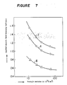
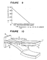
- Figures 3 to 6 show conventional piezoelectric actuators.
- Figure 3 is a perspective view of a longitudinal effect-type laminated piezoelectric actuator, wherein reference numeral 1 indicates the entire structure of a longitudinal effect-type laminated piezoelectric element (hereinafter referred to simply as a piezoelectric element 1), numeral 2 indicates a piezoelectric ceramic sheet, numeral 3 indicates an electrode, and numeral 4 indicates a power source, whereby an electric field E is applied to each piezoelectric ceramic sheet 2 via the electrode 3.
- Symbol P indicates the polarization direction of each piezoelectric ceramic sheet.
- Arrow A indicates the direction of contraction of the piezoelectric ceramic sheet 2 upon the application of the electric field E
- arrow B indicates the direction of expansion of the piezoelectric ceramic sheet 2.
- the piezoelectric element 1 is composed of several hundred piezoelectric ceramic sheets 2 each having a thickness of from 50 to 100 ⁇ m, laminated in their thickness direction and designed to utilize the longitudinal effect whereby the entire element expands in a longitudinal direction upon the application of the electric field E in the same direction as the polarization direction P.
- FIG 4 is a perspective view of a transversal effect-type piezoelectric actuator which is referred to as a unimorph-type.
- the same reference symbols as used in Figure 3 indicate the same elements
- reference numeral 5 indicates a transversal effect-type piezoelectric element (hereinafter referred to simply as a piezoelectric element 5)
- numeral 6 indicates a piezoelectric ceramic sheet
- numeral 11 is a bending metal plate bonded to one side of the piezoelectric ceramic sheet 6 with the above-mentioned electrode 3 interposed therebetween.
- the piezoelectric element 5 is composed of a piezoelectric ceramic sheet 6 having a thickness of from 100 to 500 ⁇ m and a metal plate 11 bonded to one side thereof, and it is of a type to be flexed in the direction of arrow C by the transversal effect whereby it expands in the thickness direction upon the application of the electric field E in the same direction as the polarization direction P of the piezoelectric ceramic sheet 6.
- FIG 5 is a perspective view of a transversal effect-type piezoelectric actuator which is referred to as a bimorph-type.
- the same reference symbols as in Figure 4 indicate the same elements, and reference numerals 6A and 6B indicate piezoelectric ceramic sheets, numeral 8 indicates a transversal effect-type piezoelectric element (hereinafter referred to simply as a piezoelectric element 8), and numeral 9 is a fixing means for fixing the piezoelectric element 8.
- the piezoelectric element 8 is composed of piezoelectric ceramic sheets 6A and 6B each having a thickness of from 100 to 500 ⁇ m bonded directly or with a metal intermediate electrode sheet interposed therebetween to facilitate leading out of an electrode, and it is of a type to be flexed in the direction of arrow C by the application of the electric field E to the piezoelectric ceramic sheet 6A in a direction opposite to the polarization direction P and to the other piezoelectric ceramic sheet 6B in the same direction as the polarization direction P.
- FIG 6 is a perspective view of a transversal effect-type laminated piezoelectric actuator which is referred to as a multimorph-type.
- the same reference symbols as in Figure 5 indicate the same elements, and reference numeral 10 indicates a transversal effect-type laminated piezoelectric element of multimorph-type (hereinafter referred to simply as a piezoelectric element 10).
- the piezoelectric element 10 has a structure wherein a plurality, two each in the illustrated case, of piezoelectric ceramic sheets 6A and 6B as used in the transversal effect-type piezoelectric element in Figure 5, are laminated, and it is of a type to be flexed in the direction of arrow P by the application of the electric field E to a piezoelectric element 6A′ at an upper portion above the center of the piezoelectric element 10 in a direction opposite to the polarization direction P and to a piezoelectric element 6B′ at a lower portion in the same direction as the polarization direction P.
- the conventional longitudinal effect-type laminated piezoelectric actuator as shown in Fiure 3 has a problem such that the displacement ⁇ at the end tip of cantilever is very small at a level of a few ten ⁇ m or less although the generated force F can be as large as a few hundred kg/mm2.
- the unimorph-type piezoelectric actuator as shown in Figure 4 is usually used as an oscillator for a piezoelectric buzzer, and the technique for designing such an oscillator has been almost fully established by now.
- no design has been disclosed to bring e.g. the thicknesses of the piezoelectric element and the bending supporting member to the optimum for obtaining a large displacement at the end tip of cantilever and a large generated force simultaneously.
- the bimorph-type piezoelectric acturator of a double layer structure (no intermediate sheet) as shown in Figure 5 is prepared usually by bonding a pair of piezoelectric ceramic sheets made of the same material and having the same size (and thickness). Also in this case, no product has been disclosed which is capable of providing a large displacement at the end tip of cantilever and a large generated force simultaneously.
- the transversal effect-type piezoelectric actuators as shown in Figures 4 to 6 are superior in the displacement at the end tip of cantilever by virture of the bending mode as compared with the longitudinal effect-type piezoelectric actuators, and the displacement ⁇ at the end tip of cantilever is as large as a few hundred ⁇ m, but the constraint generating force is conversely very small at a level of from a few gf to a few tens gf.
- the constraint force may be increased either by increasing the thickness of the piezoelectric ceramic sheet 6 or by reducing the length of the piezoelectric element.
- the displacement ⁇ at the end tip of cantilever is inversely proportional to the thickness and decreases in proportion to the square of the length of the piezoelectric element.
- the bimorph-type has been devised since no adequate displacement ⁇ at the end tip of cantilever and constraint generated force F have been obtained by the unimorph-type as shown in Figure 4 among the transversal effect-type piezoelectric actuators.
- the electric field E applicable is at a level of only 500 V/mm at best, while the allowable electric field E applied in the same direction as the polarization direction P is at a level of from 1 to 2 KV/mm (i.e. the level of the electric field E at which no dielectric breakdown takes place).
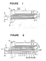
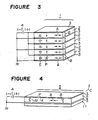
- the present invention provides a piezoelectric actuator comprising a longitudinal effect-type laminated piezoelectric element composed of piezoelectric ceramic sheets laminated in their thickness direction, and a supporting member fixed to one side in the longitudinal direction of the element and being bending and capable of constraining expansion of the element.
- a supporting member made of a non-piezoelectric bending plate capable of constraining expansion or contraction of a longitudinal effect-type laminated piezoelectric element or a supporting member made of a transversal effect-type piezoelectric element contractible in a direction opposite to the direction of expansion of the longitudinal effect-type laminated piezoelectric element is fixed to one side in the longitudinal direction of the longitudinal effect-type laminated piezoelectric element composed of piezoelectric ceramic sheets laminated in their thickness direction.
- the Young's modulus of the supporting member is at least 2.5 times the Young's modulus of the piezoelectric element; the thickness t2 of the piezoelectric element is within a range of 100 ⁇ m ⁇ t2 ⁇ 5000 ⁇ m; and the ratio of t2/t1 where t2 is the thickness of the piezoelectric element and t1 is the thickness of the supporting member, is at least 1.6.
- the direction of the application of the electric field E, the polarization direction P, the contraction direction A and the expansion direction B are the same as in Figure 3 with respect to the piezoelectric element 1 and are the same as in the case of the multimorph-type piezoelectric element 6B′ shown in Figure 6 with respect to the piezoelectric element 6B′.
- a metal plate 11 as shown in Figure 1 may be interposed between the insulating layer 12 and the piezoelectric element 6B′.
- a powder of lead titanate zirconate (PZT) as a piezoelectric material and an organic binder are kneaded together with a plasticizer, a solvent, etc. to obtain a slurry, which is then moled into a sheet by means of e.g. a doctor blade and then dried.
- the required electrode 3 is formed by screen printing.
- a plurality of the piezoelectric ceramic sheets thus prepared are laminated and press-bonded under heating to obtain a monolithic shaped product.
- each piezoelectric ceramic sheet 2 and the number of laminated sheets correspond to the length of the piezoelectric element 1 and they are determined to obtain a necessary length of the element taking into the consideration the desired applied voltage, displacement at the end tip of cantilever, generated force, etc.
- the shaped product is then cut in a direction perpendicular to the direction of the electrodes 3 so that the thickness of the piezoelectric element 1 would be about from a few hundred ⁇ m to a few thousand ⁇ m and then sintered and subjected to necessary abrasive finishing to obtain a finished element composed of piezoelectric ceramic sheets 2 laminated in the longitudinal direction of the element.
- the shaped product may be sintered as it is i.e. without cutting, and then, cut and subjected to abrasive finishing to obtain a piezoelectric element 1 in a similar fashion.
- outer connecting electrodes are fixed with inner electrodes and a lead wire is connected thereto, followed by polarization treatment.
- an epoxy resin serving both as an insulating agent and as an adhesive is coated on a metal plate 11 made of e.g. a Fe-Ni alloy to form an insulating layer 12, and then, the metal plate 11 is bonded to the piezoelectric element 1.
- a transversal effect-type laminated piezoelectric element 6B′ is sintered, then processed into a predetermined shape and subjected to polarization treatment, and thereafter an insulating layer 12 is formed in the same manner as in the case of the unimorph-type of Figure 1. Then, the element 6B′ is bonded to the piezoelectric element 1. Further, in order to facilitate the leading out of the electrodes, a bending metal plate may be inserted as an intermediate electrode plate between the transversal effect-type laminated piezoelectric element 6B′ and the insulating layer 12 and simultaneously bonded.
- a single layer transversal effect-type piezoelectric element 6B may be provided instead of the transversal effect-type laminated piezoelectric element 6B ⁇ to obtain the same function and effects.
- the direction of the application of the electric field E, the polarization direction P, the contraction direction A and the expansion direction B are the same as in the case of the piezoelectric element 1 in Figure 3.
- the longitudinal effect-type piezoelectric element 1 of a plate form thus prepared by the above steps is applied to a bending mode to obtain a unimorph-type or bimorph-type piezoelectric actuator 100 or 200 having a large displacement at the end tip of cantilever and a large generated force F.
- the piezoelectric strain will be from 2 to 3 times greater than the conventional unimorph-type piezoelectric element 5 (i.e. d33 ⁇ 2 to 3 ⁇ d31). Accordingly, the displacement ⁇ at the end tip of cantilever and the generated force F will be from 2 to 3 times larger than the conventional transversal effect-type unimorph of the same shape.
- the upper portion above the insulating layer 12 expands by means of the longitudinal effect-type piezoelectric element 1, and the lower portion below the insulating layer 12 contracts by means of the transversal effect-type piezoelectric element 6B′.
- the electric field E it is possible to apply the electric field E to the piezoelectric elements 1 and 6B′ in the same direction as the polarizing direction P, whereby depolarization which used to be a drawback of the conventional bimorph-type does not take place, and it is possible to apply the electric field E with high intensity at a level where no substantial dielectric breakdown takes place.
- the electric field applicable in the direction opposite to the polarization direction is at a level of only 500 V/mm at best.
- the piezoelectric actuator 100 or 200 of the present invention it is possible to apply a high electric field E at a level of from 1 to 2 kV/mm.
- the piezoelectric strain will be from about 2 to about 3 times larger even when the same material as the conventional material is used (d33 ⁇ 2 to 3 ⁇ d31).
- the supporting member is required to have a sufficient strength to constrain the expansion of the piezoelectric ceramic element and at the same time required to be bending. Further, when the supporting member is an electrically conductive material or a transversal effect-type piezoelectric ceramic material, it is necessary to interpose an insulating layer between it and the longitudinal effect-type piezoelectric element since electrodes are exposed on the surface of the longitudinal effect-type piezoelectric element.
- the supporting member may be made of an oxide ceramic material such as alumina, zirconia, MgAl2O4, mullite, beryllia or cordierite; a non-oxide ceramic material such as SiC, Si3N4, AlN, B4C, TiC or tungsten carbide; a metal plate such as an iron-nickel alloy; or a transversal effect-type piezoelectric ceramic element.
- oxide ceramic material such as alumina, zirconia, MgAl2O4, mullite, beryllia or cordierite
- a non-oxide ceramic material such as SiC, Si3N4, AlN, B4C, TiC or tungsten carbide
- a metal plate such as an iron-nickel alloy
- the Young's modulus of the supporting member to a level of at least 2.5 times the Young's modulus of the piezoelectric element 1 to which it is bonded, the thickness t2 of the piezoelectric element 1 within a range of 100 ⁇ m ⁇ t2 ⁇ 5000 ⁇ m and the ratio of t2/t1 where t2 is the thickness of the piezoelectric element and t1 is the thickness of the supporting member, to a level of at least 1.6.
- the Young's modulus of the two members preferably satisfy Y1 ⁇ 2.5 Y2 where Y1 is the Young's modulus of the supporting member and Y2 is the Young's modulus of the piezoelectric element. If the Young's modulus of the supporting member is less than 2.5 times the Young's modulus of the piezoelectric element, the reduction of the required intensity of the applied electric field is small. If the ratio in the thickness of the piezoelectric element to the supporting member is less than 1.6, not only the reduction in the required strength of the applied electric field decreases, but also a higher intensity of the applied electric field will be required because a supporting member having a high Young's modulus will be employed, such being disadvantageous.
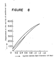
- Curves I, II and III represent 500 ⁇ m/50 gf, 500 ⁇ m/30 gf and 250 ⁇ m/25 gf, respectively, of a unimorph-type.
- the larger the work load (1/2 ⁇ F where ⁇ : displacement at the end tip of cantilever and F: generated force), the higher the effect of the Young's modulus relative to the reduction of the necessary strain. Namely, the larger the work load, the more advantageous it becomes to use a material having a high Young's modulus.
- Y2 the Young's modulus of the piezoelectric element
- Y1 the Young's modulus of the supporting member
- t2 the thickness of the piezoelectric element
- t1 the thickness of the supporting member
- the optimum thickness t2 is determined by the following equation: where F: generated force, ⁇ : displacement at the end tip of cantilever, l: length of the piezoelectric element, and b: width of the piezoelectric element.
- F generated force
- ⁇ displacement at the end tip of cantilever
- l length of the piezoelectric element
- b width of the piezoelectric element.
- the thickness t2 of the piezoelectric element satisfies the following formula I
- the thickness t1 of the supporting member satisfies the formula I: 100 ⁇ m ⁇ t2 ⁇ 5000 ⁇ m (I) t2 ⁇ m ⁇ t1 ⁇ 2 ⁇ Yt2 ⁇ m (II)
- Table 1 shows the shape of each piezoelectric actuator 100 or 200 and the conditions for the measurement.
- the unimorph-type piezoelectric actuator 100 was fixed at one end, and the displacement ⁇ at the end tip of cantilever and the generated force F at the other end were measured.
- the displacement ⁇ at the end tip of cantilever was measured by an eddy current system senser, and the generated force F was represented by the force whereby the displacement at the end tip of cantilever becomes 0.
- the bimorph-type piezoelectric actuator 200 was measured in the same manner as described above. The results thereby obtained are shown in Table 2.
- the Comparative Examples in Table 2 will be described as follows:
- the size of the piezoelectric element and the intensity of the applied electrical field were the same as in Example 1.
- a longitudinal effect-type laminated piezoelectric ceramic element was used and the supporting member was varied.
- the width of the element was 5 mm
- the length of the element was 15 mm
- the thickness of the supporting member was 60 ⁇ m
- the Young's modulus of the piezoelectric element was 5.9 ⁇ 1010 N/m2.
- Generated force: 49 gf Piezoelectric strain coefficient d33 720 ⁇ 10 ⁇ 12 m/V
- Piezoelectric strain coefficient d31 260 ⁇ 10 ⁇ 12 m/V
- Figure 8 shows the relation between the applied electric field intensity and the displacement at the end tip of cantilever
- Figure 7 shows the relation between the displacement at the end tip of cantilever and the generated force.
- a longitudinal effect-type laminated piezoelectric element is formed by laminating piezoelectric ceramic sheets in their thickness direction, and a means for constraining the expansion of the element is provided on one side in the longitudinal direction of the longitudinal effect-type laminated piezoelectric element, whereby the longitudinal effect-type laminated piezoelectric element is used in a bending mode, and it is thereby possible to obtain a piezoelectric strain coefficient of from 2 to 3 times higher than the transversal effect-type piezelectric actuator of a unimorph-type.
- the bimorph-type piezoelectric actuator of the present invention has advantages over the conventional bimorph-type and multimorph-type transversal effect-type piezoelectric elements in that it is possible to apply the electric field in the same direction as the polarization direction of the piezoelectric ceramic sheets, whereby a relatively high electric field can be applied without leading to dielectric breakdown and without requiring a means for preventing depolarization, and accordingly it is possible to obtain a large displacement at the end tip of cantilever and a large generated force.
- the required intensity of the applied electric field can be substantially reduced by adjusting the Young's modulus Y2 and Y1 of the piezoelectric ceramic element and of the supporting member to be Y1 ⁇ 2.5 Y2, the thickness t2 of the piezoelectric element to be 100 ⁇ m ⁇ t2 ⁇ 5000 ⁇ m and the ratio of t1/t2 where t2 is the thickness of the piezoelectric element and t1 is the thickness of the supporting member, to be at least 1.6. Accordingly, the generated force and the displacement at the end tip of cantilever can be increased over the conventional levels.
- the thickness t2 of the piezoelectric ceramic element satisfies the following formula I and the thickness t1 of the supporting member satisfies the following formula II, it is possible to determine the combination of the thicknesses which minimizes the necessary intensity of the applied electric filed once the materials used and the desired displacement at the end tip of cantilever and generated force are determined, whereby it is possible to increase the generated force and the displacement at the end tip of cantilever: 100 ⁇ m ⁇ t2 ⁇ 5000 ⁇ m (I) t2 ⁇ m ⁇ t1 ⁇ 2 ⁇ Y t2 ⁇ m (II)
Applications Claiming Priority (6)
| Application Number | Priority Date | Filing Date | Title |
|---|---|---|---|
| JP61228426A JP2533861B2 (ja) | 1986-09-29 | 1986-09-29 | 圧電アクチユエ−タ |
| JP228426/86 | 1986-09-29 | ||
| JP309189/86 | 1986-12-27 | ||
| JP30919086 | 1986-12-27 | ||
| JP309190/86 | 1986-12-27 | ||
| JP30918986 | 1986-12-27 |
Publications (3)
| Publication Number | Publication Date |
|---|---|
| EP0262637A2 true EP0262637A2 (de) | 1988-04-06 |
| EP0262637A3 EP0262637A3 (en) | 1990-01-03 |
| EP0262637B1 EP0262637B1 (de) | 1995-03-22 |
Family
ID=27331402
Family Applications (1)
| Application Number | Title | Priority Date | Filing Date |
|---|---|---|---|
| EP87114140A Expired - Lifetime EP0262637B1 (de) | 1986-09-29 | 1987-09-28 | Piezoelektrischer Antrieb |
Country Status (3)
| Country | Link |
|---|---|
| US (2) | US4812698A (de) |
| EP (1) | EP0262637B1 (de) |
| DE (1) | DE3751183T2 (de) |
Cited By (14)
| Publication number | Priority date | Publication date | Assignee | Title |
|---|---|---|---|---|
| FR2639086A1 (fr) * | 1988-11-17 | 1990-05-18 | Smc Corp | Dispositif de clapet a lamelles pour buse ou orifice |
| EP0408305A2 (de) * | 1989-07-11 | 1991-01-16 | Ngk Insulators, Ltd. | Piezoelektrischer/elektrostriktiver Antrieb |
| EP0516380A2 (de) * | 1991-05-28 | 1992-12-02 | Canon Kabushiki Kaisha | Mikroverschiebungselement für ein Tunnelrastermikroskop |
| US5210455A (en) * | 1990-07-26 | 1993-05-11 | Ngk Insulators, Ltd. | Piezoelectric/electrostrictive actuator having ceramic substrate having recess defining thin-walled portion |
| US5691593A (en) * | 1989-07-11 | 1997-11-25 | Ngk Insulators, Ltd. | Piezoelectric/electrostrictive actuator having at least one piezoelectric/electrostrictive film |
| WO1998040917A1 (en) * | 1997-03-07 | 1998-09-17 | Greenbrook Electrical Plc | Low component count release mechanism |
| US5889352A (en) * | 1995-10-13 | 1999-03-30 | Ngk Insulators, Ltd. | Piezo-electric/electrostrictive film type element |
| EP0993055A2 (de) * | 1998-09-18 | 2000-04-12 | Seiko Instruments Inc. | Piezoelektrischer Antrieb und elektronisches Gerät mit piezoelektrischem Antrieb |
| DE4303424C3 (de) * | 1992-02-06 | 2001-03-29 | Murata Manufacturing Co | Streifenförmiges piezoelektrisches Betätigungsglied des bimorphen Types |
| WO2004013917A2 (de) * | 2002-07-31 | 2004-02-12 | Siemens Ag | Piezoelektrischer biegewandler |
| EP1764845A1 (de) * | 2005-09-15 | 2007-03-21 | FESTO AG & Co | Piezo-Biegewandler |
| WO2007079855A1 (de) * | 2005-12-21 | 2007-07-19 | Eurocopter Deutschland Gmbh | Rotorblatt für ein drehflügelflugzeug |
| WO2007112741A1 (en) * | 2006-03-30 | 2007-10-11 | Noliac A/S | A multilayer piezoelectric bender |
| CN114569199A (zh) * | 2022-03-04 | 2022-06-03 | 悦兴(厦门)生物科技有限公司 | 高韧性陶瓷手术刀及其操作方法 |
Families Citing this family (72)
| Publication number | Priority date | Publication date | Assignee | Title |
|---|---|---|---|---|
| DE3751183T2 (de) * | 1986-09-29 | 1995-11-16 | Mitsubishi Chem Corp | Piezoelektrischer Antrieb. |
| US4928030A (en) * | 1988-09-30 | 1990-05-22 | Rockwell International Corporation | Piezoelectric actuator |
| JPH0733087B2 (ja) * | 1989-06-09 | 1995-04-12 | シャープ株式会社 | インクジェットプリンタ |
| JP2867437B2 (ja) * | 1989-07-19 | 1999-03-08 | ブラザー工業株式会社 | 圧電式インクジェットプリンタヘッド |
| JP3041952B2 (ja) * | 1990-02-23 | 2000-05-15 | セイコーエプソン株式会社 | インクジェット式記録ヘッド、圧電振動体、及びこれらの製造方法 |
| US6186619B1 (en) * | 1990-02-23 | 2001-02-13 | Seiko Epson Corporation | Drop-on-demand ink-jet printing head |
| US5402159A (en) * | 1990-03-26 | 1995-03-28 | Brother Kogyo Kabushiki Kaisha | Piezoelectric ink jet printer using laminated piezoelectric actuator |
| JP2891510B2 (ja) * | 1990-05-09 | 1999-05-17 | 日本電子株式会社 | 圧電素子駆動体 |
| US5363131A (en) * | 1990-10-05 | 1994-11-08 | Seiko Epson Corporation | Ink jet recording head |
| JP3185226B2 (ja) * | 1991-01-30 | 2001-07-09 | 株式会社村田製作所 | 圧電バイモルフ素子の駆動方法及び圧電バイモルフ素子 |
| EP0526048B1 (de) * | 1991-07-18 | 1997-11-12 | Ngk Insulators, Ltd. | Piezoelektrischer/elektrostriktiver Element mit einem keramischen Substrat aus stabilisiertem Zirkoniumdioxid |
| US5247222A (en) * | 1991-11-04 | 1993-09-21 | Engle Craig D | Constrained shear mode modulator |
| US5350966A (en) * | 1991-11-12 | 1994-09-27 | Rockwell International Corporation | Piezocellular propulsion |
| US5268611A (en) * | 1992-03-16 | 1993-12-07 | Rockwell International Corporation | Anisotropic transducer |
| US6050679A (en) * | 1992-08-27 | 2000-04-18 | Hitachi Koki Imaging Solutions, Inc. | Ink jet printer transducer array with stacked or single flat plate element |
| US5493615A (en) * | 1993-05-26 | 1996-02-20 | Noise Cancellation Technologies | Piezoelectric driven flow modulator |
| GB9317294D0 (en) * | 1993-08-19 | 1993-10-20 | Westland Helicopters | Circulation control aerofoils |
| DE4435914C2 (de) * | 1993-10-07 | 1999-02-25 | Seiko Epson Corp | Piezoelektrischer Antrieb für einen Tintenstrahlaufzeichnungskopf und Verfahren zu dessen Herstellung |
| DE4337265C1 (de) * | 1993-11-02 | 1995-03-09 | Mayer Textilmaschf | Kettenwirkmaschine mit mindestens einer Legebarre |
| US5378382A (en) * | 1993-12-09 | 1995-01-03 | Mitsubishi Kasei Corporation | Piezoelectric ceramic composition for actuator |
| US6781285B1 (en) * | 1994-01-27 | 2004-08-24 | Cymer, Inc. | Packaged strain actuator |
| US5626312A (en) * | 1994-07-06 | 1997-05-06 | Mcdonnell Douglas Corporation | Piezoelectric actuator |
| JPH09205781A (ja) * | 1995-02-01 | 1997-08-05 | Seiko Epson Corp | 圧電体発電装置及びこれを備えた携帯型電力供給装置、携帯型電子機器 |
| DE69627603T2 (de) | 1995-10-09 | 2003-12-18 | Matsushita Electric Ind Co Ltd | Beschleunigungssensor und Herstellungsverfahren hierfür, sowie Schockdetektor, der einen solchen Sensor verwendet |
| JPH09261978A (ja) * | 1996-03-25 | 1997-10-03 | Nippon Cement Co Ltd | 積層体素子および振動駆動装置 |
| DE69735411T2 (de) * | 1996-10-09 | 2006-09-07 | Symyx Technologies, Inc., Santa Clara | Infrarot-spektroskopie und abbildung von bibliotheken |
| WO1998024296A2 (en) * | 1996-11-20 | 1998-06-11 | The Regents Of The University Of California | Multilaminate piezoelectric high voltage stack |
| DE19704389C2 (de) * | 1997-02-06 | 1999-02-04 | Fraunhofer Ges Forschung | Aktor aus Einzelelementen |
| US5992032A (en) * | 1997-02-24 | 1999-11-30 | Chung-Shan Institute Of Science & Technology | Method and apparatus for inclination measurement using piezoelectric effect |
| DE19712034A1 (de) * | 1997-03-21 | 1998-09-24 | Deutsch Zentr Luft & Raumfahrt | Profilkante eines aerodynamischen Profils |
| JP3456380B2 (ja) * | 1997-09-02 | 2003-10-14 | 株式会社村田製作所 | 圧電アクチュエータ |
| JPH11168246A (ja) * | 1997-09-30 | 1999-06-22 | Matsushita Electric Ind Co Ltd | 圧電アクチュエータ、赤外線センサおよび圧電光偏向器 |
| US6494079B1 (en) | 2001-03-07 | 2002-12-17 | Symyx Technologies, Inc. | Method and apparatus for characterizing materials by using a mechanical resonator |
| US6393895B1 (en) | 1997-10-08 | 2002-05-28 | Symyx Technologies, Inc. | Method and apparatus for characterizing materials by using a mechanical resonator |
| DE19745468C1 (de) * | 1997-10-15 | 1999-04-15 | Daimler Chrysler Ag | Piezoelektrischer Aktuator |
| US6135713A (en) * | 1999-01-19 | 2000-10-24 | The Mcdonnell Douglas Helicopter Company | Helicopter rotor blade flap actuator government interest |
| US6329741B1 (en) * | 1999-04-30 | 2001-12-11 | The Trustees Of Princeton University | Multilayer ceramic piezoelectric laminates with zinc oxide conductors |
| JP2000332313A (ja) * | 1999-05-21 | 2000-11-30 | Matsushita Electric Ind Co Ltd | 薄膜圧電型バイモルフ素子及びその応用 |
| US6512323B2 (en) * | 2000-03-22 | 2003-01-28 | Caterpillar Inc. | Piezoelectric actuator device |
| DE10031877C1 (de) * | 2000-06-30 | 2001-12-20 | Fraunhofer Ges Forschung | Vorrichtung zur Ablenkung von optischen Strahlen |
| US7248444B1 (en) * | 2000-07-21 | 2007-07-24 | Lauer Mark A | Electromagnetic heads, flexures, gimbals and actuators formed on and from a wafer substrate |
| WO2002099414A1 (en) | 2001-06-06 | 2002-12-12 | Symyx Technologies, Inc. | Flow detectors having mechanical oscillators, and use thereof in flow characterization systems |
| DE10329028A1 (de) * | 2002-07-11 | 2004-01-29 | Ceram Tec Ag Innovative Ceramic Engineering | Isolierung für piezokeramische Vielschichtaktoren |
| AU2003282936A1 (en) | 2002-10-18 | 2004-05-04 | Symyx Technologies, Inc. | Environmental control system fluid sensing system and method comprising a sesnsor with a mechanical resonator |
| US7043969B2 (en) * | 2002-10-18 | 2006-05-16 | Symyx Technologies, Inc. | Machine fluid sensor and method |
| US6895645B2 (en) * | 2003-02-25 | 2005-05-24 | Palo Alto Research Center Incorporated | Methods to make bimorph MEMS devices |
| US7089635B2 (en) * | 2003-02-25 | 2006-08-15 | Palo Alto Research Center, Incorporated | Methods to make piezoelectric ceramic thick film arrays and elements |
| WO2004086027A2 (en) * | 2003-03-21 | 2004-10-07 | Symyx Technologies, Inc. | Mechanical resonator |
| US7721590B2 (en) * | 2003-03-21 | 2010-05-25 | MEAS France | Resonator sensor assembly |
| DE602004013753D1 (de) * | 2003-03-21 | 2008-06-26 | Hella Kgaa Hueck & Co | Resonator-sensor-einheit |
| DE102004025603A1 (de) * | 2004-05-25 | 2005-12-22 | Forschungszentrum Karlsruhe Gmbh | Aktor auf der Basis geometrisch anisotroper Nanopartikel |
| DE102005060779B4 (de) * | 2005-12-16 | 2008-07-10 | Eads Deutschland Gmbh | Kraftgenerator |
| US8780053B2 (en) * | 2007-03-21 | 2014-07-15 | Northwestern University | Vibrating substrate for haptic interface |
| WO2007111909A2 (en) * | 2006-03-24 | 2007-10-04 | Northwestern University | Haptic device with indirect haptic feedback |
| US8525778B2 (en) | 2007-03-21 | 2013-09-03 | Northwestern University | Haptic device with controlled traction forces |
| US20080211353A1 (en) * | 2007-03-02 | 2008-09-04 | Charles Erklin Seeley | High temperature bimorph actuator |
| US8217553B2 (en) * | 2008-08-18 | 2012-07-10 | New Scale Technologies | Reduced-voltage, linear motor systems and methods thereof |
| US8189851B2 (en) | 2009-03-06 | 2012-05-29 | Emo Labs, Inc. | Optically clear diaphragm for an acoustic transducer and method for making same |
| WO2011065235A1 (ja) * | 2009-11-25 | 2011-06-03 | 株式会社村田製作所 | 電気機械変換素子及びアクチュエータ |
| KR20110077637A (ko) * | 2009-12-30 | 2011-07-07 | 삼성전기주식회사 | 햅틱 디바이스 구동용 압전 액추에이터 |
| KR101161943B1 (ko) * | 2010-03-04 | 2012-07-04 | 삼성전기주식회사 | 햅틱 피드백 디바이스 및 전자 장치 |
| WO2011121882A1 (ja) * | 2010-03-31 | 2011-10-06 | コニカミノルタエムジー株式会社 | 積層型圧電体および積層型圧電体の製造方法ならびに前記積層型圧電体を用いた超音波トランスデューサおよび超音波診断装置 |
| DE102010021867A1 (de) * | 2010-05-28 | 2011-12-01 | Eurocopter Deutschland Gmbh | Kraftgenerator zur Anbringung an einer Struktur |
| JP5959807B2 (ja) * | 2010-08-05 | 2016-08-02 | キヤノン株式会社 | アクチュエータおよびアクチュエータ構造体 |
| US8543168B2 (en) | 2010-12-14 | 2013-09-24 | Motorola Mobility Llc | Portable electronic device |
| JP5708167B2 (ja) * | 2011-04-06 | 2015-04-30 | コニカミノルタ株式会社 | 超音波探触子及び超音波診断装置 |
| JP5644729B2 (ja) * | 2011-09-30 | 2014-12-24 | コニカミノルタ株式会社 | 超音波振動子、超音波探触子及び超音波画像診断装置 |
| US20140270279A1 (en) * | 2013-03-15 | 2014-09-18 | Emo Labs, Inc. | Acoustic transducers with releasable diaphram |
| US9613544B2 (en) * | 2013-07-31 | 2017-04-04 | North Carolina State University | Electroactive, actuated dot structures and associated methods |
| USD741835S1 (en) | 2013-12-27 | 2015-10-27 | Emo Labs, Inc. | Speaker |
| DE102015226233A1 (de) * | 2015-12-21 | 2017-01-19 | Johnson Matthey Piezo Products Gmbh | Biegewandler sowie Verfahren zu dessen Herstellung sowie zu dessen Betrieb |
| CN111551944A (zh) * | 2020-06-01 | 2020-08-18 | 中国第一汽车股份有限公司 | 一种隐藏式雷达总成及车辆 |
Citations (1)
| Publication number | Priority date | Publication date | Assignee | Title |
|---|---|---|---|---|
| US4491761A (en) * | 1981-12-28 | 1985-01-01 | United Technologies Corporation | Planar piezoelectric deflector with arrays of alternate piezoelectric effect |
Family Cites Families (13)
| Publication number | Priority date | Publication date | Assignee | Title |
|---|---|---|---|---|
| US3370187A (en) * | 1965-04-30 | 1968-02-20 | Gen Dynamics Corp | Electromechanical apparatus |
| SU285705A1 (ru) * | 1968-07-01 | 1976-07-25 | Киевский Ордена Ленина Политехнический Институт Имени 50-Летия Великой Октябрьской Социалистической Революции | Пьезоэлектрический трансформатор |
| DE2547025A1 (de) * | 1974-11-13 | 1976-05-26 | Allied Chem | Verfahren zur herstellung von epsilon-caprolactam |
| US4140936A (en) * | 1977-09-01 | 1979-02-20 | The United States Of America As Represented By The Secretary Of The Navy | Square and rectangular electroacoustic bender bar transducer |
| US4362407A (en) * | 1981-09-08 | 1982-12-07 | Piezo Electric Products, Inc. | Piezoelectric printer and piezoelectric multilam actuator used therein |
| US4625137A (en) * | 1983-12-09 | 1986-11-25 | Nippon Telegraph & Telephone Public Corp. | Piezoelectric actuator using bimorph element |
| JPS60190100A (ja) * | 1984-03-09 | 1985-09-27 | Murata Mfg Co Ltd | 圧電スピ−カ |
| GB8408659D0 (en) * | 1984-04-04 | 1984-05-16 | Syrinx Precision Instr Ltd | Rotation rate sensor |
| US4553061A (en) * | 1984-06-11 | 1985-11-12 | General Electric Company | Piezoelectric bimorph driven direct current latching relay |
| JPS62298190A (ja) * | 1986-06-18 | 1987-12-25 | Sumitomo Special Metals Co Ltd | 圧電アクチユエ−タ |
| JPS62298189A (ja) * | 1986-06-18 | 1987-12-25 | Sumitomo Special Metals Co Ltd | 圧電アクチユエ−タ |
| DE3751183T2 (de) * | 1986-09-29 | 1995-11-16 | Mitsubishi Chem Corp | Piezoelektrischer Antrieb. |
| JPH0642637A (ja) * | 1992-07-22 | 1994-02-18 | Daihatsu Motor Co Ltd | 歯車変速機の変速操作装置 |
-
1987
- 1987-09-28 DE DE3751183T patent/DE3751183T2/de not_active Expired - Fee Related
- 1987-09-28 EP EP87114140A patent/EP0262637B1/de not_active Expired - Lifetime
- 1987-09-29 US US07/102,397 patent/US4812698A/en not_active Expired - Fee Related
-
1990
- 1990-09-28 US US07/590,033 patent/US5034649A/en not_active Expired - Fee Related
Patent Citations (1)
| Publication number | Priority date | Publication date | Assignee | Title |
|---|---|---|---|---|
| US4491761A (en) * | 1981-12-28 | 1985-01-01 | United Technologies Corporation | Planar piezoelectric deflector with arrays of alternate piezoelectric effect |
Cited By (34)
| Publication number | Priority date | Publication date | Assignee | Title |
|---|---|---|---|---|
| US5076314A (en) * | 1988-11-17 | 1991-12-31 | Smc Corporation Sohka Kojo | Nozzle flapper mechanism |
| GB2225133A (en) * | 1988-11-17 | 1990-05-23 | Smc Corp | Nozzle flapper mechanism |
| US4934401A (en) * | 1988-11-17 | 1990-06-19 | Smc Corporation | Nozzle flapper mechanism |
| FR2639086A1 (fr) * | 1988-11-17 | 1990-05-18 | Smc Corp | Dispositif de clapet a lamelles pour buse ou orifice |
| US5012835A (en) * | 1988-11-17 | 1991-05-07 | Smc Corporation | Nozzle flapper mechanism |
| GB2225133B (en) * | 1988-11-17 | 1993-06-02 | Smc Corp | Nozzle flapper mechanism |
| US5592042A (en) * | 1989-07-11 | 1997-01-07 | Ngk Insulators, Ltd. | Piezoelectric/electrostrictive actuator |
| EP0408305A3 (en) * | 1989-07-11 | 1991-11-21 | Ngk Insulators, Ltd. | Piezoelectric/electrostrictive actuator |
| US5631040A (en) * | 1989-07-11 | 1997-05-20 | Ngk Insulators, Ltd. | Method of fabricating a piezoelectric/electrostrictive actuator |
| US5691593A (en) * | 1989-07-11 | 1997-11-25 | Ngk Insulators, Ltd. | Piezoelectric/electrostrictive actuator having at least one piezoelectric/electrostrictive film |
| EP0408305A2 (de) * | 1989-07-11 | 1991-01-16 | Ngk Insulators, Ltd. | Piezoelektrischer/elektrostriktiver Antrieb |
| US6441537B1 (en) | 1989-07-11 | 2002-08-27 | Ngk Insulators, Ltd. | Piezoelectric/electrostrictive actuator having at least one piezoelectric/electrostrictive film |
| US5210455A (en) * | 1990-07-26 | 1993-05-11 | Ngk Insulators, Ltd. | Piezoelectric/electrostrictive actuator having ceramic substrate having recess defining thin-walled portion |
| US5681410A (en) * | 1990-07-26 | 1997-10-28 | Ngk Insulators, Ltd. | Method of producing a piezoelectric/electrostrictive actuator |
| EP0516380A2 (de) * | 1991-05-28 | 1992-12-02 | Canon Kabushiki Kaisha | Mikroverschiebungselement für ein Tunnelrastermikroskop |
| EP0516380A3 (en) * | 1991-05-28 | 1993-06-16 | Canon Kabushiki Kaisha | Micro-displacement element for a scanning tunneling microscope |
| US5268571A (en) * | 1991-05-28 | 1993-12-07 | Canon Kabushiki Kaisha | Micro-displacement element, and scanning tunneling microscope and information processing apparatus using same |
| DE4303424C3 (de) * | 1992-02-06 | 2001-03-29 | Murata Manufacturing Co | Streifenförmiges piezoelektrisches Betätigungsglied des bimorphen Types |
| US5889352A (en) * | 1995-10-13 | 1999-03-30 | Ngk Insulators, Ltd. | Piezo-electric/electrostrictive film type element |
| WO1998040917A1 (en) * | 1997-03-07 | 1998-09-17 | Greenbrook Electrical Plc | Low component count release mechanism |
| KR100614854B1 (ko) * | 1997-03-07 | 2006-08-25 | 그린부룩 일렉트리컬 피엘씨 | 작은 개수의 구성품을 갖는 카운트 해제 기구 |
| AU724314B2 (en) * | 1997-03-07 | 2000-09-14 | Greenbrook Electrical Plc | Low component count release mechanism |
| EP0993055A3 (de) * | 1998-09-18 | 2002-05-02 | Seiko Instruments Inc. | Piezoelektrischer Antrieb und elektronisches Gerät mit piezoelektrischem Antrieb |
| EP0993055A2 (de) * | 1998-09-18 | 2000-04-12 | Seiko Instruments Inc. | Piezoelektrischer Antrieb und elektronisches Gerät mit piezoelektrischem Antrieb |
| US6720711B2 (en) | 1998-09-18 | 2004-04-13 | Seiko Instruments Inc. | Piezoelectric actuator, ultrasonic motor equipped with piezoelectric actuator, and electronic apparatus equipped with piezoelectric actuator |
| WO2004013917A2 (de) * | 2002-07-31 | 2004-02-12 | Siemens Ag | Piezoelektrischer biegewandler |
| WO2004013917A3 (de) * | 2002-07-31 | 2004-10-14 | Siemens Ag | Piezoelektrischer biegewandler |
| EP1764845A1 (de) * | 2005-09-15 | 2007-03-21 | FESTO AG & Co | Piezo-Biegewandler |
| WO2007079855A1 (de) * | 2005-12-21 | 2007-07-19 | Eurocopter Deutschland Gmbh | Rotorblatt für ein drehflügelflugzeug |
| CN101378956B (zh) * | 2005-12-21 | 2011-06-01 | 欧洲直升机德国有限责任公司 | 用于旋翼飞机的旋翼桨叶 |
| US8162607B2 (en) | 2005-12-21 | 2012-04-24 | Eurocopter Deutschland Gmbh | Rotor blade for a rotary wing aircraft |
| WO2007112741A1 (en) * | 2006-03-30 | 2007-10-11 | Noliac A/S | A multilayer piezoelectric bender |
| CN114569199A (zh) * | 2022-03-04 | 2022-06-03 | 悦兴(厦门)生物科技有限公司 | 高韧性陶瓷手术刀及其操作方法 |
| CN114569199B (zh) * | 2022-03-04 | 2023-08-25 | 悦兴(厦门)生物科技有限公司 | 高韧性陶瓷手术刀及其操作方法 |
Also Published As
| Publication number | Publication date |
|---|---|
| EP0262637A3 (en) | 1990-01-03 |
| US5034649A (en) | 1991-07-23 |
| EP0262637B1 (de) | 1995-03-22 |
| DE3751183T2 (de) | 1995-11-16 |
| US4812698A (en) | 1989-03-14 |
| DE3751183D1 (de) | 1995-04-27 |
Similar Documents
| Publication | Publication Date | Title |
|---|---|---|
| EP0262637B1 (de) | Piezoelektrischer Antrieb | |
| EP0408305B1 (de) | Piezoelektrischer/elektrostriktiver Antrieb | |
| EP0606767B1 (de) | Piezoelektrische Anordnung | |
| US7336020B2 (en) | Piezoelectric/electrostrictive device and method of manufacturing same | |
| JP3501860B2 (ja) | 圧電/電歪膜型素子及びその製造方法 | |
| EP0468796A1 (de) | Piezoelektrisches/elektrostriktives Antriebselement mit keramischem Substrat | |
| Takahashi | Multilayer piezoelectric ceramic actuators and their applications | |
| JPH05267742A (ja) | 圧電/電歪膜型素子 | |
| EP1089349B1 (de) | Piezoelektrisches/elektrostriktives Bauelement und dessen Herstellungsverfahren | |
| US8941290B2 (en) | Vibrating body and vibration wave actuator | |
| JP4038400B2 (ja) | セラミック積層体、セラミック積層体の製造方法、圧電/電歪デバイス、圧電/電歪デバイスの製造方法及びセラミック焼結体 | |
| EP1091424B1 (de) | Piezoelektrisches/elektrostriktives Bauelement und dessen Herstellungsverfahren | |
| US6476539B1 (en) | Piezoelectric/electrostrictive device | |
| EP1089351B1 (de) | Piezoelektrisches/elektrostriktives Bauelement | |
| JP4015820B2 (ja) | 配線基板及びその製造方法 | |
| US20060061240A1 (en) | Piezoelectric/electrostrictive device | |
| JP3009945B2 (ja) | 圧電/電歪膜型素子 | |
| JPH0658978B2 (ja) | 圧電変位素子 | |
| JP2571802B2 (ja) | 圧電アクチュエータ | |
| EP0794580A1 (de) | Piezoelektrischer Transformator | |
| JPS63260085A (ja) | 圧電アクチュエータ | |
| JP2533861B2 (ja) | 圧電アクチユエ−タ | |
| JP2000166260A (ja) | 圧電アクチュエータ及びその製造方法 | |
| JP4015909B2 (ja) | 圧電/電歪デバイス | |
| US20050035688A1 (en) | Piezoelectric/electrostrictive device and method of manufacturing same |
Legal Events
| Date | Code | Title | Description |
|---|---|---|---|
| PUAI | Public reference made under article 153(3) epc to a published international application that has entered the european phase |
Free format text: ORIGINAL CODE: 0009012 |
|
| AK | Designated contracting states |
Kind code of ref document: A2 Designated state(s): DE FR GB |
|
| RAP1 | Party data changed (applicant data changed or rights of an application transferred) |
Owner name: MITSUBISHI KASEI CORPORATION |
|
| PUAL | Search report despatched |
Free format text: ORIGINAL CODE: 0009013 |
|
| AK | Designated contracting states |
Kind code of ref document: A3 Designated state(s): DE FR GB |
|
| 17P | Request for examination filed |
Effective date: 19900509 |
|
| 17Q | First examination report despatched |
Effective date: 19921019 |
|
| GRAA | (expected) grant |
Free format text: ORIGINAL CODE: 0009210 |
|
| AK | Designated contracting states |
Kind code of ref document: B1 Designated state(s): DE FR GB |
|
| RAP2 | Party data changed (patent owner data changed or rights of a patent transferred) |
Owner name: MITSUBISHI CHEMICAL CORPORATION |
|
| REF | Corresponds to: |
Ref document number: 3751183 Country of ref document: DE Date of ref document: 19950427 |
|
| ET | Fr: translation filed | ||
| PLBE | No opposition filed within time limit |
Free format text: ORIGINAL CODE: 0009261 |
|
| PLBQ | Unpublished change to opponent data |
Free format text: ORIGINAL CODE: EPIDOS OPPO |
|
| PLAA | Information modified related to event that no opposition was filed |
Free format text: ORIGINAL CODE: 0009299DELT |
|
| PLBI | Opposition filed |
Free format text: ORIGINAL CODE: 0009260 |
|
| PLBF | Reply of patent proprietor to notice(s) of opposition |
Free format text: ORIGINAL CODE: EPIDOS OBSO |
|
| 26N | No opposition filed | ||
| 26 | Opposition filed |
Opponent name: HOECHST AG Effective date: 19951222 |
|
| PLBF | Reply of patent proprietor to notice(s) of opposition |
Free format text: ORIGINAL CODE: EPIDOS OBSO |
|
| PLBF | Reply of patent proprietor to notice(s) of opposition |
Free format text: ORIGINAL CODE: EPIDOS OBSO |
|
| PLAV | Examination of admissibility of opposition |
Free format text: ORIGINAL CODE: EPIDOS OPEX |
|
| PLBF | Reply of patent proprietor to notice(s) of opposition |
Free format text: ORIGINAL CODE: EPIDOS OBSO |
|
| PLBQ | Unpublished change to opponent data |
Free format text: ORIGINAL CODE: EPIDOS OPPO |
|
| PLAB | Opposition data, opponent's data or that of the opponent's representative modified |
Free format text: ORIGINAL CODE: 0009299OPPO |
|
| R26 | Opposition filed (corrected) |
Opponent name: HOECHST AG Effective date: 19951222 |
|
| PGFP | Annual fee paid to national office [announced via postgrant information from national office to epo] |
Ref country code: GB Payment date: 19970919 Year of fee payment: 11 |
|
| PGFP | Annual fee paid to national office [announced via postgrant information from national office to epo] |
Ref country code: DE Payment date: 19971031 Year of fee payment: 11 |
|
| PGFP | Annual fee paid to national office [announced via postgrant information from national office to epo] |
Ref country code: FR Payment date: 19980909 Year of fee payment: 12 |
|
| PG25 | Lapsed in a contracting state [announced via postgrant information from national office to epo] |
Ref country code: GB Free format text: LAPSE BECAUSE OF NON-PAYMENT OF DUE FEES Effective date: 19980928 |
|
| PLBQ | Unpublished change to opponent data |
Free format text: ORIGINAL CODE: EPIDOS OPPO |
|
| PLAB | Opposition data, opponent's data or that of the opponent's representative modified |
Free format text: ORIGINAL CODE: 0009299OPPO |
|
| R26 | Opposition filed (corrected) |
Opponent name: CERAMTEC AG INNOVATIVE CERAMIC ENGINEERING Effective date: 19951222 |
|
| GBPC | Gb: european patent ceased through non-payment of renewal fee |
Effective date: 19980928 |
|
| PG25 | Lapsed in a contracting state [announced via postgrant information from national office to epo] |
Ref country code: DE Free format text: LAPSE BECAUSE OF NON-PAYMENT OF DUE FEES Effective date: 19990701 |
|
| PG25 | Lapsed in a contracting state [announced via postgrant information from national office to epo] |
Ref country code: FR Free format text: LAPSE BECAUSE OF NON-PAYMENT OF DUE FEES Effective date: 20000531 |
|
| REG | Reference to a national code |
Ref country code: FR Ref legal event code: ST |
|
| DX | Miscellaneous (deleted) | ||
| PLBP | Opposition withdrawn |
Free format text: ORIGINAL CODE: 0009264 |
|
| RAP2 | Party data changed (patent owner data changed or rights of a patent transferred) |
Owner name: MITSUBISHI CHEMICAL CORPORATION |
|
| PLCK | Communication despatched that opposition was rejected |
Free format text: ORIGINAL CODE: EPIDOSNREJ1 |
|
| PLBN | Opposition rejected |
Free format text: ORIGINAL CODE: 0009273 |
|
| STAA | Information on the status of an ep patent application or granted ep patent |
Free format text: STATUS: OPPOSITION REJECTED |
|
| 27O | Opposition rejected |
Effective date: 20050523 |
|
| PLAB | Opposition data, opponent's data or that of the opponent's representative modified |
Free format text: ORIGINAL CODE: 0009299OPPO |