EP0257101A1 - Schaltregulator - Google Patents
Schaltregulator Download PDFInfo
- Publication number
- EP0257101A1 EP0257101A1 EP87901650A EP87901650A EP0257101A1 EP 0257101 A1 EP0257101 A1 EP 0257101A1 EP 87901650 A EP87901650 A EP 87901650A EP 87901650 A EP87901650 A EP 87901650A EP 0257101 A1 EP0257101 A1 EP 0257101A1
- Authority
- EP
- European Patent Office
- Prior art keywords
- power source
- transformer
- winding
- switching
- primary winding
- Prior art date
- Legal status (The legal status is an assumption and is not a legal conclusion. Google has not performed a legal analysis and makes no representation as to the accuracy of the status listed.)
- Withdrawn
Links
- 238000004804 winding Methods 0.000 claims abstract description 94
- 230000001105 regulatory effect Effects 0.000 claims description 21
- 230000001276 controlling effect Effects 0.000 claims description 6
- 239000000758 substrate Substances 0.000 description 10
- 238000010586 diagram Methods 0.000 description 4
- 238000009499 grossing Methods 0.000 description 4
- 230000003247 decreasing effect Effects 0.000 description 3
- 238000012856 packing Methods 0.000 description 2
- 238000006243 chemical reaction Methods 0.000 description 1
- 238000012423 maintenance Methods 0.000 description 1
Images

Classifications
-
- H—ELECTRICITY
- H02—GENERATION; CONVERSION OR DISTRIBUTION OF ELECTRIC POWER
- H02M—APPARATUS FOR CONVERSION BETWEEN AC AND AC, BETWEEN AC AND DC, OR BETWEEN DC AND DC, AND FOR USE WITH MAINS OR SIMILAR POWER SUPPLY SYSTEMS; CONVERSION OF DC OR AC INPUT POWER INTO SURGE OUTPUT POWER; CONTROL OR REGULATION THEREOF
- H02M3/00—Conversion of DC power input into DC power output
- H02M3/22—Conversion of DC power input into DC power output with intermediate conversion into AC
- H02M3/24—Conversion of DC power input into DC power output with intermediate conversion into AC by static converters
- H02M3/28—Conversion of DC power input into DC power output with intermediate conversion into AC by static converters using discharge tubes with control electrode or semiconductor devices with control electrode to produce the intermediate AC
- H02M3/325—Conversion of DC power input into DC power output with intermediate conversion into AC by static converters using discharge tubes with control electrode or semiconductor devices with control electrode to produce the intermediate AC using devices of a triode or a transistor type requiring continuous application of a control signal
- H02M3/335—Conversion of DC power input into DC power output with intermediate conversion into AC by static converters using discharge tubes with control electrode or semiconductor devices with control electrode to produce the intermediate AC using devices of a triode or a transistor type requiring continuous application of a control signal using semiconductor devices only
-
- H—ELECTRICITY
- H02—GENERATION; CONVERSION OR DISTRIBUTION OF ELECTRIC POWER
- H02M—APPARATUS FOR CONVERSION BETWEEN AC AND AC, BETWEEN AC AND DC, OR BETWEEN DC AND DC, AND FOR USE WITH MAINS OR SIMILAR POWER SUPPLY SYSTEMS; CONVERSION OF DC OR AC INPUT POWER INTO SURGE OUTPUT POWER; CONTROL OR REGULATION THEREOF
- H02M1/00—Details of apparatus for conversion
- H02M1/0083—Converters characterised by their input or output configuration
- H02M1/009—Converters characterised by their input or output configuration having two or more independently controlled outputs
Definitions
- the present invention relates to a switching regulator, more particularly, to a switching regulator for driving a power device using a plurality of mutually insulated DC power sources.
- a switching regulator is used for generating a plurality of mutually insulated DC power sources from one DC power source, for example, a power supply of an inverter device for driving an AC servomotor of an automated guided vehicle (AGV) by a battery source, as a power supply, in consideration of the factors of weight, conversion efficiency, and space occupied.
- one DC power source for example, a power supply of an inverter device for driving an AC servomotor of an automated guided vehicle (AGV) by a battery source, as a power supply, in consideration of the factors of weight, conversion efficiency, and space occupied.
- AGV automated guided vehicle
- one switching control circuit and one switching transistor are used to generate a chopped voltage, the chopped voltage is applied to one power transformer, and a required DC power source is then generated.
- an AC servomotor is generally used as a travelling motor or a lifting motor of the AGV, since it does not require a brush and has maintenance advantages.
- a driving power source insulated from the main power source is required.
- This driving power source is a power source for a driver circuit which amplifies a signal from a control circuit and drives high capacity power transistors, so that the AC servomotor is supplied with the controlled power source.
- the driving power sources are not only insulated from the control circuit, but also insulated from one another. For example, where one AC servomotor is driven by a three phase alternating current, six pairs of mutually insulated driving power sources are required for six driving transistors.
- a conventional switching regulator uses one switching control circuit and one switching transistor, and a chopped voltage is applied to one transformer, so that the power supply generates a required DC power source. Therefore, for example, where one AC servomotor is driven by a three phase alternating current, six pairs of mutually insulated driving power sources are required, and thus many secondary windings for the six pairs of driving power sources must be wound on the one transformer.
- the object of the present invention is to provide a switching regulator using one switching control circuit and one switching means and applying chopped voltages to many transformers simultaneously, and generating many mutually insulated DC power sources, which is small in size and has simple printed circuits.
- a switching regulator comprising: a power supply means; a switching means; a main power transformer, a primary winding of said main power transformer being connected to said power supply means via said switching means; a switching control circuit for detecting a voltage of one secondary winding of said main power transformer and controlling a duty ratio of said switching means; a first diode inserted in series with and in a forward direction to a primary winding of said main power transformer; at least one subsidiary power transformer, a primary winding of said subsidiary power transformer being connected in parallel with said primary winding of said main power transformer; and a second diode inserted in series with and in a forward direction to a primary winding of said at least one subsidiary power transformer.
- the switching regulator of the present invention uses one switching control circuit and one switching means and applies chopped voltages to many transformers simultaneously, and generates many mutually insulated DC power sources. That is, according to the switching regulator of the present invention, the one transformer having many windings is divided into many small transformers, so that the weight on the printed substrate is divided and the space occupied by the printed substrate on which the transformers are mounted, in decreased. Furthermore, the printed circuits are simplified, the printed substrate is miniaturized, and the packing density of the device is improved.
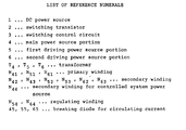
- Figure 1 is a block circuit diagram showing a part of an example of the switching regulator of the present invention, wherein reference numeral 1 denotes a DC power source, reference numeral 2 denotes a switching transistor, reference numeral 3 denotes a switching control circuit, reference numeral 4 denotes a main power source portion, reference numeral 5 denotes a first driving power source portion, and reference numeral 6 denotes a second driving power source portion.
- reference numeral 1 denotes a DC power source
- reference numeral 2 denotes a switching transistor
- reference numeral 3 denotes a switching control circuit
- reference numeral 4 denotes a main power source portion
- reference numeral 5 denotes a first driving power source portion
- reference numeral 6 denotes a second driving power source portion.
- the DC power source is a battery or an output of a rectifier circuit
- the voltage E is applied to a primary winding N 41 of a transformer (main power transformer) T 4 in the main power source portion 4 via the switching transistor 2 and a breaking diode 45 for circulating current is inserted in series with and in a forward direction to the primary winding N 41 .
- the voltage E is also applied to a primary winding N 51 of a transformer (subsidiary power transformer) T 5 in the first driving power source portion 5 via the switching transistor 2 and a breaking diode 55 for circulating current inserted in series with and in a forward direction to the primary winding N 51 .
- the voltage E is also applied to a primary winding N 61 of a transformer (subsidiary power transformer) T 6 in the second driving power source portion 6 via the switching transistor 2 and a breaking diode 65 for circulating current inserted in series with and in a forward direction to the primary winding N 61 .
- the switching control circuit 3 controls a ratio (duty ratio) between a switching ON time and a period of the switching transistor 2 by making use of pulse width modulation (PWM).
- PWM pulse width modulation
- This switching transistor 2 is driven by a high speed period, for example, a period of 40 KHz, and therefore, a MOS type FET can be used as the switching transistor 2 to enable a high speed operation.
- each secondary winding In the secondary side of the transformer T 4 in the main power source portion 4, there are provided secondary windings N 42 , N43 and a secondary winding N 44 for a controlled system power source, each secondary winding generates a required DC power source respectively by a rectifier diode and a smoothing condenser connected to each secondary winding.
- the secondary winding N 42 supplies DC 24 Volts for use in an interface
- the secondary winding N 43 supplies DC +15 Volts for use in an analog differential amplifier
- the secondary winding N 44 supplies DC 5 Volts for use in a main power source of a speed control circuit in need of a high capacity.
- a part of an output of the secondary winding N 44 for use in the main power source returns to the switching control circuit 3 and controls a driving signal of the switching transistor 2 in order to control the output voltage to a constant voltage.
- the secondary windings N 52 , N S3 and a regulating winding N 54 of the controlled system power source a rectifier diode and a smoothing condenser is connected to each of these windings, and each winding generates a required DC power source respectively.
- the secondary windings N 52 and N5 3 supply DC 7.5 Volts and DC-4 Volts for use in one driving transistor, respectively.
- an AC servomotor is driven by a three phase alternating current
- three driving power source portions are required by one AC servomotor, since two driving transistors are used as one phase of the three phase alternating current. Therefore, where three AC servomotors are driven by a three phase alternating current, nine driving power source portions are provided in parallel with the power supply in order to drive a power device.
- each output voltage of the secondary windings N 52 and N 53 in the first driving power source portion 5 is a constant voltage.
- the second driving power source portion 6 is the same as the first driving power source portion 5; and in the secondary side of the transformer T 6 , there are provided secondary windings N 62 . N63 and a regulating winding N64 , so that constant voltages of DC power sources are generated by each winding. When loads of the secondary windings N 62 . N 63 have a low value, then the energy of the transformer T 6 is transferred through from the regulating winding N 64 to the output of the secondary winding N 44 .
- Such a driving power source portion is not only for the first driving power source portion 5 and the second driving power source portion 6, but also for many driving power source portions (for example, nine portions) connected in parallel therewith, as described above.
- These driving power source portions are fixed on a printed substrate close to the driving transistor, the printed circuits required by each driving power source portions can be simplified by only connecting the primary windings and the regulating winding to each transformer, so that the printed substrate per se can be miniaturized. Since the one large transformer is divided into many small transformers, the number of connecting pins of each divided transformer is decreased. Consequently, the divided transformers can be miniaturized and the weight of the printed substrate on which the divided transformers are fixed can be spread. Furthermore, chopped voltages generated by one switching control circuit 3 and one switching transistor 2 are applied to many transformers, and thus there is an advantage in a decrease of the cost of the power supply.
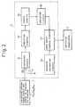
- Figure 2 is a block diagram showing a switching control circuit.
- the controlled system power source (the output of the secondary winding N 44 for the controlled system power source) of the main power source portion 5, and the output (power source A) of the regulating winding N 54 of the main power source portion and the output of the regulating winding N 64 of the second driving power source portion 6 are returned to the switching control circuit 3.
- the power source A for example, DC 5 Volts
- a voltage E for example, DC 5 Volts of a constant-voltage
- This photo-coupler 34 is used for floating the output of the amplifier circuit 33, and the output of the photo-coupler 34 is amplified by an amplifier circuit 35 and is transferred to a duty ratio control circuit 37 as an input signal.
- the duty ratio control circuit 37 generates a prescribed pulse width signal which is determined by a constant period sawtooth wave signal generated by a sawtooth generating circuit 36 and by an output of the amplifier circuit 35, so that the ratio (duty ratio) between a switching ON time and a period of the switching transistor 2 is determined by the output signal of the duty ratio control circuit 37.
- the voltage E of the DC power source 1 is applied to the primary winding N 41 of the transformer T 4 through a breaking diode for controlling a circulating current 45, to the primary winding N 51 of the transformer T 5 through a breaking diode for controlling a circulating current 55, and to the primary winding N 61 of the transformer T 6 through a breaking diode for controlling a circulating current 65 respectively. Therefore, in the secondary windings N 42 ' N 43 and the secondary winding N 44 for the controlled system power source of the transformer T 4 , the secondary windings N 52 . N 53 and the regulating winding N 54 of the transformer T 5 ' and the secondary windings N 62 .
- the switching transistor 2 is switched OFF, then the polarity of the voltages applied to the transformers T 4 , T 5 and T 6 is inverted, and electrical conduction occurs in the rectifier diodes of the secondary windings N 42 N43 and the secondary winding N 44 for controlled system power source of the transformer T 4 , in the rectifier diodes of the secondary windings N 52 , N 53 and the regulating winding N 54 of the transformer T 5 , and in the rectifier diodes of the secondary windings N 62 , N 63 and the regulating winding N 64 of the transformer T 6 , so that the energy stored in the tranformers T 4 , T 5 and T 6 is transferred to the smoothing condenser and to the output of each winding respectively.
- the breaking diodes 45, 55 and 65 are provided for circulating current in a forward direction with the DC power source 1 (the direction is the reverse of the direction current flow when the switching transistor 2 is cut off), therefore the energy stored in the transformers T 4 , T 5 and T 6 is not transferred to the primary windings N 41 . N 51 and N 61 respectively.
- the required DC power sources can be given in accordance with the number of turns of each secondary winding.
- the power source a returned to the switching control circuit 3 is not only connected to the output of the secondary winding N 44 for controlled system power source in the main power source 4, but also to the output of the regulating winding N 54 in the first driving power source portion 5 and to the output of the regulating winding N 64 in the second driving power source portion 6. Consequently, the outputs of the secondary windings N 52 , N 53 of the transformer T 5 and the secondary windings N 62 ' N 63 of the transformer T 6 can be stabilized, and the secondary windings N 42 ' N 43 of the transformer T also can be stabilized.
- the excessive energy in the regulating winding N 54 of the transformer T 5 or the regulating winding N 64 of the transformer T 6 is transferred to the secondary winding N 44 for controlling the system power source respectively.
- the switching regulator of the present invention uses one switching control circuit and one switching means and applies chopped voltages many transformers simultaneously, and generates many mutually insulated DC power sources. Therefore, the transformers can be small size and the printed circuit can be simplified, the space occupied by the printed substrate on which the transformers are fixed can be reduced and miniaturized, and furthermore, there is an advantage of a decreased in the cost of the power supply.
Landscapes
- Engineering & Computer Science (AREA)
- Power Engineering (AREA)
- Dc-Dc Converters (AREA)
Applications Claiming Priority (2)
| Application Number | Priority Date | Filing Date | Title |
|---|---|---|---|
| JP37475/86 | 1986-02-24 | ||
| JP61037475A JPS62196071A (ja) | 1986-02-24 | 1986-02-24 | パワ−デバイス駆動用電源 |
Publications (2)
| Publication Number | Publication Date |
|---|---|
| EP0257101A1 true EP0257101A1 (de) | 1988-03-02 |
| EP0257101A4 EP0257101A4 (de) | 1988-06-23 |
Family
ID=12498546
Family Applications (1)
| Application Number | Title | Priority Date | Filing Date |
|---|---|---|---|
| EP19870901650 Withdrawn EP0257101A4 (de) | 1986-02-24 | 1987-02-23 | Schaltregulator. |
Country Status (5)
| Country | Link |
|---|---|
| US (1) | US4809151A (de) |
| EP (1) | EP0257101A4 (de) |
| JP (1) | JPS62196071A (de) |
| KR (1) | KR880701034A (de) |
| WO (1) | WO1987005165A1 (de) |
Cited By (3)
| Publication number | Priority date | Publication date | Assignee | Title |
|---|---|---|---|---|
| EP0410866A1 (de) * | 1989-07-28 | 1991-01-30 | Bull S.A. | Vorrichtung für Energieumwandlung mit Mehrfachausgang |
| EP0609900A3 (de) * | 1993-02-05 | 1994-10-19 | Lincoln Electric Co | Wechselrichter-Leistungsversorgung für das Schweissen. |
| ES2101640A1 (es) * | 1994-10-24 | 1997-07-01 | Telefonica Nacional Espana Co | Circuito convertidor de alimentacion. |
Families Citing this family (28)
| Publication number | Priority date | Publication date | Assignee | Title |
|---|---|---|---|---|
| FR2618957B1 (fr) * | 1987-07-31 | 1989-11-17 | Dassault Electronique | Dispositif d'alimentation electrique, en particulier pour un generateur d'ondes pour un radar a impulsions |
| DE3906600A1 (de) * | 1989-03-02 | 1990-09-13 | Vogt Electronic Ag | Schaltnetzteil |
| US5113337A (en) * | 1991-02-08 | 1992-05-12 | General Electric Company | High power factor power supply |
| FR2691853B1 (fr) * | 1992-06-01 | 2002-12-20 | Smh Man Services Ag | Appareil pour charger un accumulateur d'énergie électrique rechargeable. |
| DE4426017C2 (de) * | 1994-07-22 | 1998-01-29 | Walter Dr Ing Soehner | Stromversorgungsgerät, insbesondere Batterie-Ladegerät für Elektrofahrzeuge oder dergleichen |
| JP2002514378A (ja) | 1997-01-24 | 2002-05-14 | シンクォール・インコーポレーテッド | 高効率電力変換装置 |
| US7269034B2 (en) | 1997-01-24 | 2007-09-11 | Synqor, Inc. | High efficiency power converter |
| JPH10295079A (ja) * | 1997-04-18 | 1998-11-04 | Yaskawa Electric Corp | トランジスタインバータ装置の多軸用電源回路及びその単位回路 |
| US6205036B1 (en) * | 1999-04-21 | 2001-03-20 | Nagano Japan Radio Co., Ltd. | Energy transfer unit, charge unit, and power supply unit |
| JP3280635B2 (ja) * | 1999-04-21 | 2002-05-13 | 長野日本無線株式会社 | エネルギー移送装置および蓄電システム |
| JP3280641B2 (ja) * | 1999-09-08 | 2002-05-13 | 長野日本無線株式会社 | エネルギー移送装置 |
| JP2004080851A (ja) * | 2002-08-09 | 2004-03-11 | Aisin Aw Co Ltd | 駆動用電源装置 |
| JP4193536B2 (ja) * | 2003-03-24 | 2008-12-10 | 横河電機株式会社 | スイッチング電源 |
| WO2007142656A2 (en) * | 2006-06-01 | 2007-12-13 | Exaflop Llc | Data center uninterruptible power distribution architecture |
| JP4208018B2 (ja) * | 2007-02-16 | 2009-01-14 | サンケン電気株式会社 | 直流変換装置 |
| US8080900B2 (en) * | 2007-07-18 | 2011-12-20 | Exaflop Llc | Direct-coupled IT load |
| CN103036443A (zh) * | 2011-09-30 | 2013-04-10 | 台达电子企业管理(上海)有限公司 | 一种有源多路隔离的输出电源 |
| US8193662B1 (en) | 2011-10-17 | 2012-06-05 | Google Inc. | Power supply source blending and smoothing |
| US9032250B1 (en) | 2012-11-05 | 2015-05-12 | Google Inc. | Online testing of secondary power unit |
| DE102012222934A1 (de) * | 2012-12-12 | 2014-06-12 | Siemens Aktiengesellschaft | Stromversorgungseinrichtung für mehrere galvanisch voneinander getrennte Verbraucher |
| US10199950B1 (en) | 2013-07-02 | 2019-02-05 | Vlt, Inc. | Power distribution architecture with series-connected bus converter |
| US20150280580A1 (en) * | 2014-03-28 | 2015-10-01 | Hep Tech Co., Ltd. | Power conversion apparatus |
| JP6515549B2 (ja) * | 2015-01-22 | 2019-05-22 | 富士電機株式会社 | マルチ出力電源装置 |
| JP6438858B2 (ja) * | 2015-07-03 | 2018-12-19 | 日立オートモティブシステムズ株式会社 | 電力変換装置 |
| WO2017203666A1 (ja) * | 2016-05-26 | 2017-11-30 | 三菱電機株式会社 | フライバック電源、インバータ及び電動車両 |
| WO2020029036A1 (zh) * | 2018-08-06 | 2020-02-13 | 深圳配天智能技术研究院有限公司 | 电动汽车和车载空调压缩机的开关电源 |
| US12308673B2 (en) * | 2019-03-21 | 2025-05-20 | Hefei Gotion High-Tech Power Energy Co., Ltd. | Active equalizer circuit, battery management system, and power supply system |
| JP7578111B2 (ja) * | 2022-03-02 | 2024-11-06 | 株式会社デンソー | 絶縁電源装置 |
Family Cites Families (7)
| Publication number | Priority date | Publication date | Assignee | Title |
|---|---|---|---|---|
| US3569818A (en) * | 1969-07-22 | 1971-03-09 | Hughes Aircraft Co | Multiple output dc voltage regulator |
| JPS5840912B2 (ja) * | 1978-11-16 | 1983-09-08 | 横河電機株式会社 | 多段dc/dcコンバ−タ |
| IE49593B1 (en) * | 1979-05-18 | 1985-10-30 | Gen Electric Co Ltd | Transistor switching circuit |
| JPS58162783A (ja) * | 1982-03-20 | 1983-09-27 | Toyoda Autom Loom Works Ltd | 可変容量型斜板圧縮機 |
| JPS58162783U (ja) * | 1982-04-21 | 1983-10-29 | 日本ビクター株式会社 | スイツチング電源回路 |
| JPS5959085A (ja) * | 1982-09-28 | 1984-04-04 | Toshiba Electric Equip Corp | 電源装置 |
| GB8325703D0 (en) * | 1983-09-26 | 1983-10-26 | Farnell Instr Ltd | Power supply |
-
1986
- 1986-02-24 JP JP61037475A patent/JPS62196071A/ja active Pending
-
1987
- 1987-02-23 WO PCT/JP1987/000118 patent/WO1987005165A1/ja not_active Ceased
- 1987-02-23 KR KR1019870700973A patent/KR880701034A/ko not_active Ceased
- 1987-02-23 EP EP19870901650 patent/EP0257101A4/de not_active Withdrawn
- 1987-02-23 US US07/124,798 patent/US4809151A/en not_active Expired - Fee Related
Cited By (5)
| Publication number | Priority date | Publication date | Assignee | Title |
|---|---|---|---|---|
| EP0410866A1 (de) * | 1989-07-28 | 1991-01-30 | Bull S.A. | Vorrichtung für Energieumwandlung mit Mehrfachausgang |
| FR2650410A1 (fr) * | 1989-07-28 | 1991-02-01 | Bull Sa | Dispositif convertisseur d'energie a sorties multiples |
| US5038265A (en) * | 1989-07-28 | 1991-08-06 | Bull S.A. | Power supply with multiple outputs and load balancing |
| EP0609900A3 (de) * | 1993-02-05 | 1994-10-19 | Lincoln Electric Co | Wechselrichter-Leistungsversorgung für das Schweissen. |
| ES2101640A1 (es) * | 1994-10-24 | 1997-07-01 | Telefonica Nacional Espana Co | Circuito convertidor de alimentacion. |
Also Published As
| Publication number | Publication date |
|---|---|
| EP0257101A4 (de) | 1988-06-23 |
| KR880701034A (ko) | 1988-04-22 |
| US4809151A (en) | 1989-02-28 |
| JPS62196071A (ja) | 1987-08-29 |
| WO1987005165A1 (fr) | 1987-08-27 |
Similar Documents
| Publication | Publication Date | Title |
|---|---|---|
| US4809151A (en) | Switching regulator having parallel diode isolated primary windings and plural secondary windings | |
| US6426884B1 (en) | Reducing reverse currents in a synchronous rectifier circuit | |
| KR100471093B1 (ko) | 전원장치 | |
| US5291383A (en) | Simplified UPS system | |
| US4395675A (en) | Transformerless noninverting buck boost switching regulator | |
| US5583753A (en) | Parallel control type DC--DC converter | |
| EP0243061A2 (de) | Netzabschalter mit Batteriereserve | |
| US7272021B2 (en) | Power converter with isolated and regulated stages | |
| US5717303A (en) | DC motor drive assembly including integrated charger/controller/regenerator circuit | |
| US5282122A (en) | High voltage power supply topology suited for miniaturization | |
| JP5332031B2 (ja) | トランス結合型昇圧器のスイッチング制御方法 | |
| US9866129B2 (en) | Power conversion device including primary inverter, transformer, secondary converter, and controller | |
| EP2040365B1 (de) | Durchflusswandler mit selbstgetriebenen, synchronen Gleichrichtern | |
| JP7070830B2 (ja) | スイッチング電源装置 | |
| US6104623A (en) | Multiple output converter having secondary regulator using self-driven synchronous rectifiers | |
| US7663898B2 (en) | Switching power supply with direct conversion off AC power source | |
| US4455596A (en) | Flyback-forward boost switchmode converter | |
| ES2143406A1 (es) | Convertidor conmutado con multiples salidas reguladoras. | |
| JP3330232B2 (ja) | 交直流無停電電源装置 | |
| US4752705A (en) | Off-gate circuit for a GTO thyristor | |
| EP1440501B1 (de) | Motorsteuerungsschaltung und zugehörige vollbrückenschaltanordnung | |
| EP0607246B1 (de) | Geregelte hilfstromversorgung | |
| JP2004357457A (ja) | チャージポンプ駆動回路 | |
| US4588906A (en) | Regulator circuit | |
| GB2243961A (en) | DC-DC Power supply circuit |
Legal Events
| Date | Code | Title | Description |
|---|---|---|---|
| PUAI | Public reference made under article 153(3) epc to a published international application that has entered the european phase |
Free format text: ORIGINAL CODE: 0009012 |
|
| 17P | Request for examination filed |
Effective date: 19871113 |
|
| AK | Designated contracting states |
Kind code of ref document: A1 Designated state(s): DE FR GB |
|
| A4 | Supplementary search report drawn up and despatched |
Effective date: 19880623 |
|
| STAA | Information on the status of an ep patent application or granted ep patent |
Free format text: STATUS: THE APPLICATION HAS BEEN WITHDRAWN |
|
| 18W | Application withdrawn |
Withdrawal date: 19891215 |
|
| RIN1 | Information on inventor provided before grant (corrected) |
Inventor name: OTA, NAOTO |