EP0254261B1 - Verfahren zum Zusammenstellen von Waren - Google Patents
Verfahren zum Zusammenstellen von Waren Download PDFInfo
- Publication number
- EP0254261B1 EP0254261B1 EP87110507A EP87110507A EP0254261B1 EP 0254261 B1 EP0254261 B1 EP 0254261B1 EP 87110507 A EP87110507 A EP 87110507A EP 87110507 A EP87110507 A EP 87110507A EP 0254261 B1 EP0254261 B1 EP 0254261B1
- Authority
- EP
- European Patent Office
- Prior art keywords
- goods
- conveyor
- merging
- storage
- unit
- Prior art date
- Legal status (The legal status is an assumption and is not a legal conclusion. Google has not performed a legal analysis and makes no representation as to the accuracy of the status listed.)
- Expired - Lifetime
Links
Images


Classifications
-
- B—PERFORMING OPERATIONS; TRANSPORTING
- B65—CONVEYING; PACKING; STORING; HANDLING THIN OR FILAMENTARY MATERIAL
- B65G—TRANSPORT OR STORAGE DEVICES, e.g. CONVEYORS FOR LOADING OR TIPPING, SHOP CONVEYOR SYSTEMS OR PNEUMATIC TUBE CONVEYORS
- B65G1/00—Storing articles, individually or in orderly arrangement, in warehouses or magazines
- B65G1/02—Storage devices
- B65G1/04—Storage devices mechanical
- B65G1/137—Storage devices mechanical with arrangements or automatic control means for selecting which articles are to be removed
- B65G1/1373—Storage devices mechanical with arrangements or automatic control means for selecting which articles are to be removed for fulfilling orders in warehouses
- B65G1/1378—Storage devices mechanical with arrangements or automatic control means for selecting which articles are to be removed for fulfilling orders in warehouses the orders being assembled on fixed commissioning areas remote from the storage areas
-
- B—PERFORMING OPERATIONS; TRANSPORTING
- B65—CONVEYING; PACKING; STORING; HANDLING THIN OR FILAMENTARY MATERIAL
- B65G—TRANSPORT OR STORAGE DEVICES, e.g. CONVEYORS FOR LOADING OR TIPPING, SHOP CONVEYOR SYSTEMS OR PNEUMATIC TUBE CONVEYORS
- B65G2209/00—Indexing codes relating to order picking devices in General
- B65G2209/02—Batch order forming, e.g. several batches simultaneously
Definitions
- This invention relates to a method for merging goods. Particularly, it relates to a method for merging goods, wherein switching time loss for merging goods is reduced and merging capacity is increased by reducing the frequency of switching for merging goods, counting errors are reduced and merging capacity is increased by counting the goods before they are transferred on a storage line (line on which goods are temporarily stored before merged), and merging capacity (number of goods/time) is maintained generally in a constant level irrespective of the sizes of goods by setting a space between adjacent goods generally constant, the goods being conveyed after merged.
- Japanese patent publication No. 58-23294 discloses the art in which in order to obtain a good balancing of the arrangement of goods which are to be transferred to a main stream conveyor from various branch stream conveyors, the goods are carried out starting from those on a downstream side branch stream conveyor and ending to those on an upperstream side conveyor, and thereafter goods are carried out starting from those on an upperstream side branch stream conveyor and ending to those on a downstream side branch stream conveyor.
- Japanese patent early laid-open publication No. 51-20358 discloses the art in which the priority of carrying-out goods (i.e., the order of goods to be carried out) is established according to instructions from a goods carry-out port, a conveying order of goods rows is established from such established priority regarding the carrying-out of goods and the loading state of a conveyor, and the goods are then forwarded on the conveyor through various goods inlet ports based on such established-conveying order of the goods rows.
- Japanese patent early laid-open publication No. 51-151954 discloses the art in which after it is detected that all goods merged on a main conveyor line have passed the merging point at the most downstream side waiting conveyor line of a plurality of waiting conveyor lines where goods to be conveyed are waiting, the succeeding goods are merged.
- Japanese patent early laid-open publication No. 59-69314 discloses the art in which when a stopper opening-and-closing sequence of a subline is built in a memory unit provided with a subline number in the direction of a data inlet/outlet line and with a tact in the address direction, an area of the memory unit is diagonally allocated to form diagonal tacts, the diagonal tacts each necessarily including only a stopper open information "1" of one subline, the stoppers of the remaining sublines all including a close information "0", in this way, the contents of open/close memory of a subline being arranged in the memory unit comprising a shift registor, etc., goods being transferred on a main line by opening or closing the stoppers which are each disposed at an outlet port of each subline according to the stopper open-and-close informations which are arranged as discribed previously.
- a method for merging goods according to the precharacterizing part of claim 1 is known.
- a plurality of storage lines are provided which are associated to dispensing units for dispensing and supplying items to the storage lines. These items are grouped in a plurality of units corresponding to a plurality of different orders. Each of the units includes two or more separate items or goods of various kinds. The items of each unit are carried out by a carrying out means and are then fed on a merging conveyor.
- a first object of the present invention is to provide a method for measuring goods, in which goods are efficiently and rapidly merged by reducing a time loss which is often taken place when a switching action for merging goods is performed, even in the case various kinds of goods having different sizes are merged.
- a second object of the present invention is to provide a method for merging goods, in which goods are efficiently and rapidly merged by preventing a counting error for goods to be conveyed and merging the goods at a high speed.
- a third object of the present invention is to provide a method for merging goods, in which goods are efficiently and rapidly merged by maintaining a generally constant space between adjacent goods which are being conveyed after merged.
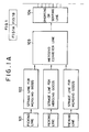
- Fig. 1 is a block diagram showing one example of a physical distribution system to which a method for merging goods according to the present invention is applied.
- 101 denotes a picking line wherein goods are picked up by a picking apparatus as one lot of same item of goods based on a predetermined batch picking data.
- 102 denotes a storage line wherein goods conveyed from the picking line 101 are temporarily stored and taken out as one lot of a predetermined amount of goods to be forwarded to a line to follow based on the batch picking data.
- 103 denotes a merging conveyor line wherein goods are arrived from each storage line 102 starting from the line on which a predetermined number of goods have been loaded to merge with goods from other lines based on the batch picking data.
- 104 denotes a diverting or sorting line wherein goods are divided and sorted into a plurality of groups based on the diverting data or sorting group data which have been prepared beforehand according to the predetermined dimensions for one assembly of goods.
- 105 denotes an assembly/storage line on which such diverted goods are temporarily stored.
- 106 denotes a carry-out line wherein the goods are carried out from each assembly/storage line 105 in the unit of a container when a container identification number (truck number) is specified.
- 107 denotes a loading conveyor line wherein the carried-out goods are transferred to the loading stations.
- 108 denotes loadings and 109 denotes deliveries. The whole system from the picking line 101 to the loading conveyor line 107 is automatically controlled by a computer.
- Fig. 2 denotes a block diagram showing one example of a control system which is controlled by a computer.
- This control system comprises a host computer (central processing unit) 201, a physical distribution control computer 202, a facilities control computer 203 and a sorting system 204.
- the host computer (CPU) 201 controls the physical distribution system as a whole. For Example, it prepares a schedule for delivery based on the data of received-orders, etc. and outputs the schedule to a downstream physical distribution control computer 202.
- the physical distribution control computer 202 determines groups of goods based on the delivery schedule, prepares diverting data and batch picking data, and outputs the data to the facilities control computer 203.
- the facilities control computer 203 prepares the required control commands based on the diverting and batch picking data, and outputs them to the sorting system 204.
- the sorting system 204 controls the merging, diverting and carring-out of the goods with a sequencer.
- Fig. 4 (A) is a schematic plan view showing an important part of a sorting system which constitutes the physical distribution system of Fig. 1, and Fig. 4 (B) is a schematic sectional view taken along line A-A of Fig. 4 (A).
- 301 denotes a container on which goods are to be loaded
- 302 denotes a container loader
- 303 denotes assembly/storage lines
- 304 denotes a diverting line.
- the assembly/storage lines 303 and the diverting line 304 are provided in two layers.
- 303-1 denotes an assembly/storage line from which goods are now being carried to a container
- 303-2 denotes another assembly/storage line on which goods are now being sorted.
- the goods are expressed by tiny square marks corresponding to the dimensions of the various goods.
- Step S1 Before Step S1,....A container volume is divided into a plurality of sections.
- the volume of a container (body of a delivery truck) 301 is divided into six sections as denoted by (1), (2), (3), (4), (5), and (6). That is, as the container 301 is of the type having a door (a take-in/take-out door) at the rear side thereof, the volume of the container is longitudinally divided into six sections. As goods having a larger length and/or width should be placed under other goods to stabilize the load during delivery, the number (integer) of the sections is determined by dividing the length of the container by the length of a comparatively large good. In this embodiment, the moving direction of the container 301 is the same as the longitudinal direction of the goods. However, the present invention is not necessarily limited to this.
- Step S2 ....Determination of a sum of good length for assembling and storing.
- the length of goods for assembly/storage is deliberately determined so that one assembly/storage line 303 can substantially store the quantity of goods which can be contained in one section of the container. Accordingly, as is shown in Figs. 4(A) and 4(B), the goods which are stored on the assembly/storage line 303 (1) are to be loaded in the section (1) of the container 301. Similarly, the goods which are stored on the assembly/storage lines 303 (2), (3), (4) and (5) are to be consecutively loaded in the sections (2), (3), (4), and (5) of the container 301. Because there are no goods which are to be loaded in the section (6) of the container 301 (goods are divided into five groups), the section (6) is left vacant.
- table 1 the alphabetical letters a through g denote items of goods which are arranged in the order of lengths as shown in Figs. 4 (A) and 4 (B). As is apparent from table 1, the order fluctuates widely by items.
- the destinations or stores are rearranged in the order of loading while the goods are arranged in the order of length. Then, based on the table 1, for each store, from the first store or destination the quantity of an item of goods is multiplied with its length, and the resulting goods of each item are added to obtain the sum from the left to the right. When the sum almost reaches the length of one assembly/storage line, collection of data is suspended. The goods which have been counted by then are grouped as one group, and attached with a line number (1) for the goods grouped. The diverting data are prepared so that the particular group should be diverted to and stored on the line (1).
- a total 145 pieces of goods for 15 stores or destinations are divided into five groups by taking into consideration the length of an assembly/storage line, volume of a container, delivery efficiency, etc. That is, the group (1) which is divided into five includes 29 pieces of goods in total; 21 pcs. for the store No. 1, 6 pcs. for the store No. 2, and 2 pcs. for the store No. 3. similarly, the group (2) which is divided into five includes 27 pieces of goods in total; 1 pcs. for the store No. 3, 21 pcs. for the store No. 4 and 5 pcs. for the store No. 5. Likewise, the group (3) which is divided into five includes 31 pieces of goods in total; 6 pcs. for the store No.
- the group (4) which is divided into five includes 30 pieces of goods in total; 5 pcs. for the store No. 8, 5 pcs. for the store No. 9, 12 pcs. for the store No. 10, and 8 pcs. for the store No. 11.
- the group (5) which is divided into five includes 28 pieces of goods in total: 2 pcs. for the store No. 11, 7 pcs. for the store No. 12, 9 pcs. for the store No. 13, 7 pcs. for the store No. 14, and 3 pcs. for the store No. 15.
- the numbers of the five groups meet more or less the number of 30 pieces of goods.
- the order listed in the table 1 is determined according to the number of destinations and the order of delivery for each container (one truck) by the host computer (CPU) 201.
- Step S4 (Step S4); Preparation of batch picking data.
- a plurality of goods are arranged or assembled for each container and almost all the assembly/storage lines 303 are allocated with goods which are divided in the unit of one container.
- the total of the goods are then regarded as the whole picking volume.
- the number of goods on the assembly/storage lines becomes a picking number, which is 3000 in the above table 1.
- the number of goods is summed for all the containers in the unit of items.
- Picking data are then prepared in such a manner as to pick up the goods in the order of lengths.
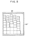
- the container 301 is loaded with the goods in a predetermined state, one example of which is shown in principle in Fig. 5.
- reference numeral 301 ⁇ denotes a door of the container.
- the method according to the present invention offers the following advantages.
- data on a plurality of (occasionally singular) destinations for delivery as well as the order of delivery are calculated for each container (each truck) by the host computer (CPU) 201 and thereafter the above-mentioned calculation is processed by the physical distribution control computer 202 to generate a batch picking data, and based on such generated batch picking data, goods are picked up in batch thereby to pick up goods for a plurality of containers simultaneously at higher efficiency compared to the prior art picking method which was limited to one container volume.
- the method according to present invention enables to store goods over the entire length of an assembly/storage line within the sectional volume of a container by determining the number of goods with the number of sections of the container. Therefore, compared to the prior art assembly/storage method which was limited to one store or destination, an excellent space efficiency can be obtained.
- goods are arranged in the order of length of items of goods a , b , c , d , e , f , and g .
- goods are carried out from the assembly/storage line 303 (1) to be sequentially loaded in the section (1) of the contaniner 301.
- the goods intended for the stores No. 1 and 2 and a part of those intended for the store No. 3 are piled up in the unit of items.
- this will not bother a distributor (driver) at all because when he opens the door of the container he will find the goods in good order only if he distributes the goods which are to be delivered to the store Nos. 1 to 3 in the order of the store No. 3, the store No. 2, and then the store No. 1.
- the driver can take out the goods in the order as he faces when he opened the door of the container. This achieves substantially the same effect as the goods are loaded in accordance with the stores.
- the distributor can efficiently unload the goods.
- the distributor can have other workers load the goods beforehand, he can deliver the goods loaded in another container during that time.
- the distribution schedule for the distributor can be more effectively planned.
- Fig. 6 is a plan view schematically showing one embodiment of an apparatus for merging goods according to the present invention.
- 1 denotes three sets of storage conveyors which constitute the storage line 102 of Fig. 1.
- the goods which were picked up based on the afore-described batch picking data and temporarily stored are loaded one after another.
- a predetermined amount of such loaded goods form a unit of items which are to be successiveively carried out.
- 2 denotes three sets of carry-out conveyors mounted on the carry-out end of each storage conveyor 1 and adapted to carry out the goods in the unit of a lot (as merging unit) but by separating the goods into individual goods.
- 3A and 3B denote merging conveyors which are disposed generally perpendicular to the carry-out conveyor 2 and adapted to convey the carried-out goods.
- the carry-out conveyors 2 and the merging conveyors 3A and 3B constitute the merging conveyor line 103 of Fig. 1 which is adapted to convey a predetermined amount of goods on each storage conveyor 1 in the unit of a merging lot to a line to follow.
- the merging conveyor 3B is disposed at angles passing through a floor pit FP provided on the floor as shown in Fig. 6 and is adapted to transfer the goods to a switching conveyor 4 (see Fig. 11) which is disposed downstair.
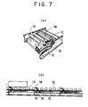
- the storage conveyor 1 is constituted as an accumulation conveyor having an accumulation function and a singulation release function (a simultaneously carrying-out function).
- the storage conveyor 1 has a sufficient length (for example, 30 m) necessary for storing goods forming a unit of merging items which are to be consecutively carried out. That is, the storage conveyor 1, as shown in Figs.
- the conveyor 1 also includes an air circuit (not shown) bypassing the mechanical valve 1d so that the goods can be released singulation and carried out simultaneously.
- the rear end portion (about 5 m long) of the storage conveyor 1 is not provided with the sensing roller nor the lifting mechanism.
- the pad chain 1C is normally pressed against the carrier rollers 1A.
- another type of conveyor as disclosed in the Japanese patent publicaiton No. 58-27167 may be employed.
- Fig. 7(B) the goods is represented by a square mark on the carrier rollers 1.
- the carry-out conveyor 2 is a conveyor of the type, in which the goods are singulated and skewedly carried out.
- the conveyor 2 comprises belt feeders 2A and 2B, and a skewed merging conveyor 2C arranged in series with the belt feeders 2A and 2B.
- the skewed merging conveyor 2C includes driven skewed wheels 2d and free rollers 2E.
- the belt feeder 2B and the skewed merging conveyor 2C are driven at a higher speed than the belt feeder 2A.
- a curve conveyor may be employed.
- PH3 and PH4 denote photo-switches adapted to detect the completion of the carry-out of the goods.
- the merging conveyor 3A in the merging apparatus comprises a roller conveyor, and the merging conveyor 3B comprises a belt conveyor. These merging conveyors 3A and 3B are driven at the same speed as the skewed merging conveyor 2C.
- Fig. 6 31 denotes a carrier storage conveyor which is adapted to convey and temporarily store the goods which were picked up.
- the carrier storage conveyor 31 comprises an accumulation conveyor similar to the storage conveyor 1. This carrier storage conveyor 31 is not necessarily required to have the function to release singulation and carry out goods simultaneously.
- the goods counting apparatus 32 denotes a goods counting apparatus.
- the goods counting apparatus 32 comprises belt conveyors 32A and 32B, and photo-switches PH1 and PH2. Because the belt conveyor 32A is driven at a higher speed than the carrier storage conveyor 31 and the belt conveyor 32B is driven at a higher speed than the belt conveyor 32A, the goods which are being conveyed can be singulated and counted by the photo-switches PH1 and PH2.
- the belt conveyors 32A and 32B are driven by a motor with a brake (not shown), respectively.
- the counting apparatus 32 such an apparatus as shown in Fig. 10 may be used.
- the counting apparatus 32 of Fig. 10 is constituted in the same manner as the embodiment of Fig. 9 except that the former is provided with an item checking apparatus 32C for checking the item of goods generally at the same time when the goods are counted.
- the item checking apparatus 32C comprises a gate type frame including photo-switches PH5 and PH6 on both lower ends thereof, and a power cylinder for lifting the gate type frame.
- the power cylinder includes an encoder.
- One side wall of the gate type frame is provided with a dog 32C ⁇ for two limit switches (not shown) for detecting the limit position of the lifting movement of the gate type frame.
- an outer configuration detecting apparatus for detecting the outer configuration by means of a pattern recognition, etc.
- a height detecting apparatus by means of supersonic wave etc. a length detecting apparatus by means of shading time of a photo-switch
- an item detecting apparatus using a bar code for detecting the weight of a photo-switch
- a weight detecting apparatus by means of load cell, etc.
- Fig. 11(A) is a plan view schematically showing one example of a goods sorting apparatus which constitutes the physical distribution system together with the apparatus for merging goods according to the present invention.
- Fig. 11(B) is a sectional view taken along line A-A of Fig. 11(A)
- Fig. 11(C) is a side view taken along line B-B of Fig. 11(A).
- the goods sorting apparatus of this example is disposed downstair of the goods merging apparatus of the present invention.
- 4 denotes a switching conveyor. As shown in Fig. 11(B), the right end of the switching conveyor 4 moves up and down to convey goods to either carrier conveyor 5 or 15, the carrier conveyors 5 and 15 being horizontally disposed in vertically parallel relation or in two layers.
- 6 and 16 denote index feeders for providing a predetermined space between adjacent goods which have been conveyed on the carrier conveyors 5 and 15 via the switching conveyor 4.
- 7 and 17 denote diverting conveyors which constitute the diverting or sorting line 104 of Fig. 1 including a diverting apparatus.
- the diverting conveyors 7 and 17 are adapted to divert goods based on the diverting or sorting group data into a plurality of lead-in conveyors 8 and 18 which are disposed generally perpendicular to the diverting conveyors 7 and 17.
- 9 and 19 denote inclined roller conveyors which constitute the assembly/storage line 105 of Fig. 1.
- the inclined roller conveyors 9 and 19 are adapted to allow the goods, which have been transferred by the lead-in conveyors 8 and 18, to advance by their own gravity on the slope to be assembled and stored.
- 10 and 20 denote carry-out apparatuses which constitute the carry-out line 106 of Fig. 1.
- the stopper means is released to carry out goods in the unit of container each line (see Figs. 13(A) and 13(B)).
- 11 and 21 denote carrier conveyors which constitute the carry-out line 106 of Fig. 1 together with the carry-out apparatuses 10 and 20.
- the carrier conveyors 11 and 21 are adapted to convey the goods which have been carried out by the carry-out apparatuses 10 and 20 to a loading station for a container.
- 12 and 22 denote transfer feeders
- 13 and 23 denote stoppers.
- the goods which have been transferred to the loading station for a container are further transferred to a loading conveyor 14 (which corresponds to the container loader 302 of Fig. 4), which constitutes the conveyor line 107 of Fig. 1, by the transfer feeders 12 and 22 and the stoppers 13 and 23.
- a switching chute 14A is disposed as shown in Fig. 11(C) in a manner when the goods are carried out from the upper carrier conveyor 11, the chute 14A is lowered to be connected and when goods are carried out from the lower conveyor 21, the chute 14A is raised to be disconnected at the position shown by broken lines.
- the goods are transferred from the loading conveyor 14 to the container 301 by workers.
- Fig. 11(A) the overflow lines 26 and 27 shown in the left side is adapted to store goods which cannot be diverted as no diverting data are supplied.
- the goods which have been picked up based on the afore-described batch picking data by the picking equipment (not shown) disposed at the upperstream of the carrier storage conveyor 31 are conveyed to the counting apparatus 32 by the carrier storage conveyor 31.
- the goods are loaded on the storage conveyor 1 (the carring-out of the goods on the storage conveyor 1 has not been completed yet)
- the belt conveyors 32A and 32B of the counting apparatus 32 are being stopped when the first goods arrives at the counting apparatus 32, such goods are stored on the carrier storage conveyor 31 without any space between adjacent goods.
- the belt conveyors 32A and 32B are driven, and the goods on the carrier storage conveyor 31 are stored on the storage conveyor 1 while being counted by the photo-switches PH1 and PH2.
- the goods are not loaded on the storage conveyor 1, because the belt conveyors 32A and 32B are driven when goods arrive at the counting apparatus 32, the goods are stored on the storage conveyor 1 while being counted by the counting apparatus 32.
- the goods can be singulated and counted by the photo-swithches PH1 and PH2. That is, as shown in Fig. 9(C), when the photo-switches PH1 and PH2 are shaded in the order of A , B , and C , they count as "one piece of goods has passed".
- the counted goods are conveyed to and stored on the storage conveyor 1.
- the method is carried out using a counting apparatus 32 including an item checking apparatus 32C as shown in Fig. 10, the goods are counted and almost simultaneously checked with the item thereof by moving the photo-switches PH5 and PH6 to predetermined heights (for example, with reference to the height of goods as shown in Fig. 10(D), the photo-switch PH5 is moved to a position lower than the reference height by about 5 mm, while the photo-switch PH6 is moved to a position higher than the reference height by about 15 mm) based on the batch picking data including such data such as the order of conveying goods, number of conveying goods, and outer dimension of the goods.
- predetermined heights for example, with reference to the height of goods as shown in Fig. 10(D)
- the photo-switch PH5 is moved to a position lower than the reference height by about 5 mm
- the photo-switch PH6 is moved to a position higher than the reference height by about 15 mm
- the batch picking data including such data
- the power cylinder is detected with the lifting amount by means of counting a pulse of the encoder and is stopped when the detected result conforms to the outer dimension of the goods based on the batch picking data.
- the power cylinder is stopped when the detected result conforms to a command signal showing the height of the goods.
- the belt conveyors 32A and 32B are stopped.
- the goods which are being conveyed are counted and almost at the same time the counted value is checked whether it conforms to the outer dimensions of the goods with reference to the conveying goods data, and as a result, when they are detected as "not conformed", the belt conveyors 32A and 32B are stopped.
- the photo-switches PH5 and PH6 are lifted to the height of the following goods by the power cylinder. If the next following goods arrives before the lifting has been completed to shade the photo-switch PH1, the belt conveyors 32A and 32B are immediately stopped.
- the belt conveyors 32A and 32B are driven again.
- all goods are checked with the item.
- only the first and last goods of each group of the goods which are flowing in succession may be checked with generally the same result as in the case where all of the goods are checked. Therefore, in the case another item checking apparatus having a comparatively low processing capacity for calculation, etc. is used instead of the photo-switches PH5 and PH6, all of the goods are not necessarily checked.
- the goods which have passed the counting apparatus 32 reach the storage conveyor 1, they are stored thereon without leaving any space between adjacent goods since the carry-out conveyor 2 is stopped.
- the storing is completed when the goods have been stored generally over the entire length of the storage conveyor 1, i.e., when a unit of merging items comprising a predetermined number of goods have been formed on the storage conveyor 1.
- the completion of the storage of the goods means that based on the data on the storage length from the batch picking data, the time required for storing the goods including the first goods to the last goods without any space between adjacent goods after the last goods have passed the photo-switch PH2 (i.e., after the photo-switch PH2 returned to its position for allowing light to enter) was counted by a controlling apparatus (not shown), the last goods passed the photo-switch PH2, and the said time has passed, i.e., all goods have been stored without any space between adjacent goods.
- the belt feeders 2A and 2B are driven when the last goods is counted.
- the belt feeders 2A and 2B are stopped when the first good arrives at the photo-switch PH3. In this way, the goods are now ready to
- one unit of merging items usually comprises a plurality of items, although there is a case where the unit of items comprises only one item.
- the switching frequency for merging becomes less compared with the case where goods are merged for each unit of items.
- a time loss for switching can be reduced.
- a merging capacity can be increased without increasing the conveying speed of goods when the goods are merged.
- the storage conveyor 1 is changable in speed in four stages and suitably changed its carrying-out speed according to the dimensions of the goods. More specifically, it is divided into four sections in the goods conveying direction according to the various lengths of the goods, i.e., less than 330mm, from 330mm to 390mm, from 390mm to 530mm, and 530mm or more.
- the goods carrying-out speeds become 21.2m/min., 25.5m/min.., 28.4m/min., and 33.8m/min. corresponding to each section of the goods.
- the space between adjacent goods which are being carried out can be arranged generally constant irrespective of the dimensions of the goods. Accordingly, the number of the goods which are carried out for a unit time can be made generally constant.
- the carrying-out speed is changed according to the section including the smaller goods.
- the goods are usually included in a section within the dimensions of one good.
- the storage conveyor 1 is changed in the predetermined speed based on the batch picking data.
- the goods on the storage conveyor 1 are consecutively carried out (all goods are simultaneously advanced using the singulation release function) on the carry-out conveyor 2 without any space between adjacent goods.
- the goods are singulated, accelerated and carried out on the merging conveyor 3A by the carry-out conveyor 2.
- the goods are skewed by the skewed merging conveyor 2C and carried out on the merging conveyor 3A.
- the speed remains unchanged if the carrying-out is performed at this speed
- the completion of the carrying-out of the goods is known by determing that the photo-switch PH4 corresponding to the carrying-out storage conveyor 1 is in the state where light is allowed to enter therein when the photo-switch PH3 is in the state where light is allowed to enter therein for two seconds continuously.
- the starting time of the carrying-out of the goods is adequately controlled. That is, when the carrying-out of the goods from the storage conveyor to be merged to the downstream side of the merging conveyor 3A has been completed and the carrying-out of the goods from the storage conveyor 1 to be merged to the upperstream side of the merging conveyor 3A is started, the next following carrying-out is started at the same time the carrying-out has been completed (when the photo-switch PH3 is in the state where light is allowed to enter therein for two seconds continuously, the other photo-switch PH4 is in the state where light is allowed to enter therein).
- the next following carrying-out is started when the photo-switch PH4 corresponding to the storage conveyor 1 from which the goods are carried out next becomes the state where light is allowed to enter therein after a predetermined time (the time required for carrying out goods to each the photo-switch PH4 corresponding to the storage from which the goods are carried out next) has passed after the carrying-out had been completed. Therefore, in this embodiment, the required time from the completion of the carrying-out of goods to the start of the carrying-out of the next following goods becomes as shown in table 3 listed hereunder.
- Figs. 12(A) and 12(B) are illustrations for explaining the action of diverting conveyors 7 and (17), wherein Fig. 12(A) is a plan view and Fig. 12(B) is a front view.
- a plurality of conveyors 7A transfer goods (not shown) in the direction as shown by an arrow a .
- a purality of skewed wheels 7B are provided each with the rotary shaft 7C disposed at predetermined angles with respect to the advancing axis of the conveyor belt 7A.
- the rotary shaft 7C is supported by a bracket 7D so that the skewed wheel 7B can rotate freely.
- the bracket 7D is supported by a pop-up device 7E through an arm 7F.
- One set of the diverting conveyors 7 and (17) are provided to each of the plurality of lead-in conveyors 8 and (18) shown in Fig. 11(A).
- the diverting conveyors 7 and (17) for the required lead-in conveyors 8 and (18) move goods in the direction as shown by an arrow c and transfer the same to a lead-in conveyor (not shown), because the dkewed wheels are pushed up, by the pop-up divice 7E, in the direction as shown by an arrow b and brought to the positions shown by the broken lines in Fig. 12(B).
- Figs. 13(A) and 13(B) are illustrations for explaining the action of the carry-out apparatuses 10 (20) of Fig. 11 adapted to carry out goods which are stored on the assembly/storage line 105 of Fig. 1, wherein Fig. 13(A) is a plan view and Fig. 13(B) is a sectional view taken along the line A-A of Fig. 13(A).
- Fig. 13(B) goods unshown are self-advanced on the free rollers 10A in the direction as shown by an arrow d .
- the goods are normally stopped from advancing because a lever 10E is positioned in the generally vertical direction to push up a frame 10C by a carry-out cylinder 10D and therefore a stopper 10B and a plurality of lifting channels 10F are kept at positions above the top surface of each free roller 10A.
- the cylinder 10D causes the lever 10E to turn in the direction as shown by an arrow e .
- the frame 10C is caused to turn about a shaft 10G in the direction as shown by an arrow f , the stopper 10B and the lifting channels 10F are lowered than the top surface of each free roller 10A. Due to the foregoing, the goods unshown resume the self-advance and are transferred to the carrier conveyors 11 (21) by a drive wheel 10H.
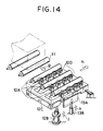
- Fig. 14 is an illustration for explaining the action of the transfer feeders 12 and (22) and the stoppers 13 and (23) of Fig. 11 which are adapted to transfer goods (shown by one dot chain lines), which have been installed on the carrier conveyors 11 and (21) to be transferred in the direction as shown by an arrow g , onto the loading conveyor 14 (in the case of an upper loading conveyor 14, the goods are transferred thereon through a switching chute) of Fig. 11 which is disposed in the direction as shown by an arrow h .
- the present invention is not limited to these.
- the storage line 102 is not necessarily required three pieces.
- the storage line 102 is disposed above and the assembly/storage line 105 is disposed thereunder, these lines may be disposed at a same level.
- a time loss which occurs when the switching for merging is performed can be reduced, thereby to merge the goods efficiently and rapidly.
- goods can be merged at a high speed without counting errors to occur, thereby to merge the goods efficiently and rapidly.
- a conveying space between adjacent goods after merged can be maintain generally constant, thereby to merge the goods efficiently and rapidly.
Claims (2)
- Verfahren zum Zusammenstellen von Waren, mit den Stufen
Bilden einer Wareneinheit jeweils auf einer Mehrzahl von Förderbändern, wobei die Wareneinheit eine Mehrzahl verschiedener Gegenstände aufweist;
Aufeinanderfolgendes Heraustragen einer Wareneinheit aus jeder der Mehrzahl von Förderbändern in der Reihenfolge der Vervollständigung des Lagerns der Wareneinheit auf jeder der Mehrzahl von Lagerbändern, erst nachdem die Wareneinheit auf jeder der Mehrzahl von Lagerbändern gelagert wurde; und
Zusammenstellen jeder der aufeinanderfolgenden herausgetragenen Wareneneinheit aus jeder der Mehrzahl von Lagerbändern,
gekennzeichnet durch die Stufen
Bilden in jeder Wareneinheit Gruppen von Gegenständen, die die gleiche Länge haben mit einer wachsenden Ordnung in Förderrichtung; und
Ändern der Austragungsgeschwindigkeit der Waren von jeder der Mehrzahl von Lagerbändern entsprechend der Länge von Gegenständen, die auf diesen angeordnet sind, so daß ein Förderabstand der Waren im wesentlichen konstant nach dem Zusammenstellen ist, unabhängig von den Längen der Gegenstände, die die Wareneinheit bilden. - Verfahren zum Zusammenstellen von Waren nach Anspruch 1, mit den Stufen:
Auswählen einer Wareneinheit entsprechend einem vorbestimmten Postenauswählwert;
Zählen einer Anzahl von Waren in jeder Einheit; und
Sortieren der Waren in eine Mehrzahl von Gruppen basierend auf einem vorbestimmten Größenwert, nachdem die Waren zusammengestellt wurden.
Applications Claiming Priority (6)
| Application Number | Priority Date | Filing Date | Title |
|---|---|---|---|
| JP174267/86 | 1986-07-24 | ||
| JP174265/86 | 1986-07-24 | ||
| JP17426586A JPH06104502B2 (ja) | 1986-07-24 | 1986-07-24 | 物品の合流方法及びその装置 |
| JP17426786A JPH06104504B2 (ja) | 1986-07-24 | 1986-07-24 | 物品の合流方法及びその装置 |
| JP174266/86 | 1986-07-24 | ||
| JP17426686A JPH06104503B2 (ja) | 1986-07-24 | 1986-07-24 | 物品の合流方法及びその装置 |
Publications (2)
| Publication Number | Publication Date |
|---|---|
| EP0254261A1 EP0254261A1 (de) | 1988-01-27 |
| EP0254261B1 true EP0254261B1 (de) | 1992-06-24 |
Family
ID=27323909
Family Applications (1)
| Application Number | Title | Priority Date | Filing Date |
|---|---|---|---|
| EP87110507A Expired - Lifetime EP0254261B1 (de) | 1986-07-24 | 1987-07-20 | Verfahren zum Zusammenstellen von Waren |
Country Status (3)
| Country | Link |
|---|---|
| US (1) | US5007521A (de) |
| EP (1) | EP0254261B1 (de) |
| DE (1) | DE3779966T2 (de) |
Families Citing this family (29)
| Publication number | Priority date | Publication date | Assignee | Title |
|---|---|---|---|---|
| LU88017A1 (de) * | 1991-10-14 | 1993-05-17 | Wurth Paul Sa | Antrieb fuer automatische lanzenwechselvorrichtungen |
| JP3189188B2 (ja) * | 1993-03-19 | 2001-07-16 | 花王株式会社 | 物品の積付け装置及び方法 |
| NL9300552A (nl) * | 1993-03-26 | 1994-10-17 | Ernestus Johannes Antonius Hui | Werkwijze en inrichting voor de productiebeheersing en expeditie van dagverse voedingswaren. |
| JP2767530B2 (ja) * | 1993-05-06 | 1998-06-18 | 花王株式会社 | 物品の集荷方法及び装置 |
| US5678680A (en) * | 1994-04-13 | 1997-10-21 | Sft Ag Spontanfoerdertechnik | Method and arrangement for producing consolidated lines of products |
| US5553442A (en) * | 1994-10-06 | 1996-09-10 | James River Paper Company, Inc. | Robotic system for mixing articles in containers |
| US5564890A (en) * | 1994-12-21 | 1996-10-15 | Progressive Solutions, Inc. | Product handling process |
| AT406151B (de) * | 1995-04-12 | 2000-03-27 | Peem Foerderanlagen Gmbh | Einrichtung zum verteilen von stückgut |
| US5697753A (en) * | 1995-09-19 | 1997-12-16 | Recot, Inc. | Semiautomatic stacker for stackable articles |
| US5794416A (en) * | 1996-10-16 | 1998-08-18 | Recot, Inc. | Computer controlled system for loading pallets in a confined cargo area |
| US6011998A (en) * | 1997-05-09 | 2000-01-04 | Lichti; Wayne | High speed picking system |
| FI972481A (fi) * | 1997-06-12 | 1998-12-13 | Jopamac Ab Oy | Menetelmä ja kuljetinjärjestelmä eri lähteistä tulevien tuotteiden ryhmittelemiseksi |
| WO1999061355A1 (en) * | 1998-05-29 | 1999-12-02 | Ridg-U-Rak, Inc. | Powered conveyor system |
| US6269609B2 (en) * | 1999-06-15 | 2001-08-07 | Quad/Graphics, Inc. | Apparatus for selective wrapping of products and a method thereof |
| US7102095B2 (en) * | 2001-11-01 | 2006-09-05 | Quad/Graphics, Inc. | Co-mailing apparatus and method |
| AT414329B (de) * | 2002-07-11 | 2007-09-15 | Tgw Transportgeraete Gmbh | Übergabeeinrichtung für stückhaftes fördergut |
| JP2006500300A (ja) * | 2002-09-20 | 2006-01-05 | シーメンス アクチエンゲゼルシヤフト | アキュムレーションコンベヤシステム |
| US7228954B2 (en) * | 2005-06-23 | 2007-06-12 | Laitram, L.L.C. | Method for conveying tires |
| AT503473B1 (de) | 2006-02-16 | 2013-07-15 | Salomon Automation Gmbh | Automatisiertes system und verfahren zum automatischen kommissionieren oder konsolidieren von artikeln |
| DE102009041239A1 (de) * | 2009-09-11 | 2011-03-24 | Krones Ag | Vorrichtung und Verfahren zum Bilden einer Gebindesequenz |
| PE20131406A1 (es) | 2010-12-06 | 2013-12-16 | Fleetwoodgoldcowyard Inc | Acumulador de transportador para controlar el flujo de articulos que se estan transportando |
| NL2011460C2 (en) * | 2013-09-18 | 2015-03-19 | Copal Dev B V | A method for processing a stream of items into sub-streams; an assembly; and a module. |
| US10308442B2 (en) * | 2014-02-28 | 2019-06-04 | Itoh Denki Co., Ltd. | Conveyed-object discharge device |
| WO2016026655A1 (de) * | 2014-08-22 | 2016-02-25 | Siemens Aktiengesellschaft | Sortiervorrichtung für gegenstände und verfahren zum sortieren von gegenständen |
| US9533837B2 (en) * | 2014-12-18 | 2017-01-03 | Compac Technologies Limited | Article carrier apparatus |
| US9688479B1 (en) | 2015-09-21 | 2017-06-27 | Amazon Technologies, Inc. | Multiple speed conveyor storage system |
| US9896271B1 (en) | 2016-09-29 | 2018-02-20 | Barry-Wehmiller Container Systems, Inc. | Conveyor accumulator for controlling the flow of articles being conveyed |
| CH715062A1 (de) | 2018-06-01 | 2019-12-13 | Ferag Ag | Kommissionieranlage und Verfahren zum Betrieb einer Kommissionieranlage. |
| CN114476453B (zh) * | 2021-12-30 | 2023-04-04 | 太仓坤泰精密模具有限公司 | 一种智能仓储设备、方法、终端及存储介质 |
Citations (1)
| Publication number | Priority date | Publication date | Assignee | Title |
|---|---|---|---|---|
| EP0244805A2 (de) * | 1986-05-09 | 1987-11-11 | Kao Corporation | Verfahren und System zum Sortieren von Gütern |
Family Cites Families (21)
| Publication number | Priority date | Publication date | Assignee | Title |
|---|---|---|---|---|
| US2599906A (en) * | 1945-06-16 | 1952-06-10 | Paul M Farmer | Article dispensing and distributing system |
| US3122231A (en) * | 1960-06-21 | 1964-02-25 | Cutler Hammer Inc | Memory type storage conveyor system |
| US3118549A (en) * | 1960-08-30 | 1964-01-21 | Cutler Hammer Inc | Storage conveyor system |
| US3173557A (en) * | 1962-02-16 | 1965-03-16 | Electrolux Ab | Conveyor system |
| US3181713A (en) * | 1962-04-19 | 1965-05-04 | Gen Electric | Article handling system |
| JPS5120358A (en) * | 1974-08-07 | 1976-02-18 | Nippon Steel Corp | Konbeaheno butsupintonyuseigyohoho narabini sonosochi |
| JPS51151954A (en) * | 1975-06-18 | 1976-12-27 | Ishikawajima Harima Heavy Ind Co Ltd | Con veyed material controlling equipment |
| IE43322B1 (en) * | 1975-10-20 | 1981-01-28 | Mechanised Order Dispensing | Improvements relating to the collation on packages |
| JPS5823294B2 (ja) * | 1977-10-25 | 1983-05-14 | 三菱電機株式会社 | 合流制御装置 |
| US4240538A (en) * | 1977-12-27 | 1980-12-23 | Harris Corporation | Method and apparatus for accumulating and gating articles |
| JPS5827167B2 (ja) * | 1978-12-26 | 1983-06-08 | ト−ヨ−カネツ株式会社 | アキユムレ−シヨンコンベヤ |
| DE2938757A1 (de) * | 1979-09-25 | 1981-04-02 | Willy Bruxelles Goossens | Lagervorrichtung |
| FR2510528B1 (fr) * | 1981-07-30 | 1987-04-30 | Jaffre Felicien | Perfectionnements aux transporteurs a rouleaux avec accumulation de charges |
| JPS5823294A (ja) * | 1981-08-05 | 1983-02-10 | Ebara Corp | ポンプ運転状態監視方式 |
| JPS5827167A (ja) * | 1981-08-11 | 1983-02-17 | Toshiba Corp | 現像装置 |
| US4534462A (en) * | 1981-11-16 | 1985-08-13 | Pentek Corporation | Motion detector and control system for an accumulating live conveyor |
| US4609091A (en) * | 1982-08-09 | 1986-09-02 | Dorner Mfg. Corp. | Storage unit for a conveyor system |
| US4499987A (en) * | 1982-08-30 | 1985-02-19 | Long Charles P | Accumulator for a carton filling and packing production line |
| JPS5969314A (ja) * | 1982-10-12 | 1984-04-19 | Hitachi Ltd | 搬送機合流制御方法 |
| FR2555917B1 (fr) * | 1983-12-02 | 1988-01-15 | Hotchkiss Brandt Sogeme | Machine de tri a debit ameliore |
| US4618341A (en) * | 1984-10-11 | 1986-10-21 | Champion International Corporation | Tube positioning and transfer system |
-
1987
- 1987-07-20 EP EP87110507A patent/EP0254261B1/de not_active Expired - Lifetime
- 1987-07-20 DE DE8787110507T patent/DE3779966T2/de not_active Expired - Fee Related
-
1990
- 1990-07-23 US US07/555,782 patent/US5007521A/en not_active Expired - Fee Related
Patent Citations (1)
| Publication number | Priority date | Publication date | Assignee | Title |
|---|---|---|---|---|
| EP0244805A2 (de) * | 1986-05-09 | 1987-11-11 | Kao Corporation | Verfahren und System zum Sortieren von Gütern |
Also Published As
| Publication number | Publication date |
|---|---|
| DE3779966D1 (de) | 1992-07-30 |
| EP0254261A1 (de) | 1988-01-27 |
| US5007521A (en) | 1991-04-16 |
| DE3779966T2 (de) | 1992-12-10 |
Similar Documents
| Publication | Publication Date | Title |
|---|---|---|
| EP0254261B1 (de) | Verfahren zum Zusammenstellen von Waren | |
| US11066241B2 (en) | Two-stage picking by means of sorter having high-dynamic sorter trays | |
| US4835702A (en) | Method of sorting goods and system therefor | |
| US7137234B2 (en) | Vertical flat stacking apparatus and method of use | |
| US9278376B2 (en) | Tray handling system and process | |
| US20040073333A1 (en) | System, method, and program for sorting objects | |
| EP0339610B1 (de) | Verfahren und Vorrichtung zum Kommissionieren von Artikeln bei Umdrehen einer Verpackung | |
| US5803703A (en) | Case loading system | |
| US4189273A (en) | Modular warehouse conveyor system | |
| US20070084764A1 (en) | Bi-directional sort mechanism and method of use | |
| KR20020043613A (ko) | 이중폭 크로스벨트 분류기 | |
| US20050222708A1 (en) | Single pass sequencer and method of use | |
| WO2000020309A1 (en) | Compact multiple pallet palletising system | |
| JP4296254B2 (ja) | ピッキング装置及び方法 | |
| CN117396415A (zh) | 分拣系统及其运行方法 | |
| US20230322488A1 (en) | System for order fulfilment | |
| JP2882982B2 (ja) | 自動仕分け倉庫システム | |
| JPH0314721B2 (de) | ||
| JPH06104504B2 (ja) | 物品の合流方法及びその装置 | |
| JPH0772003B2 (ja) | 計数方法 | |
| JP3125091B2 (ja) | 物品の保管荷揃え方法 | |
| JPS62264116A (ja) | 物品の仕分け方法およびその装置 | |
| JPH06104502B2 (ja) | 物品の合流方法及びその装置 | |
| JPH03238203A (ja) | 仕分け装置 | |
| JPH06104503B2 (ja) | 物品の合流方法及びその装置 |
Legal Events
| Date | Code | Title | Description |
|---|---|---|---|
| PUAI | Public reference made under article 153(3) epc to a published international application that has entered the european phase |
Free format text: ORIGINAL CODE: 0009012 |
|
| AK | Designated contracting states |
Kind code of ref document: A1 Designated state(s): CH DE FR GB IT LI SE |
|
| 17P | Request for examination filed |
Effective date: 19880610 |
|
| 17Q | First examination report despatched |
Effective date: 19900327 |
|
| GRAA | (expected) grant |
Free format text: ORIGINAL CODE: 0009210 |
|
| AK | Designated contracting states |
Kind code of ref document: B1 Designated state(s): CH DE FR GB IT LI SE |
|
| REF | Corresponds to: |
Ref document number: 3779966 Country of ref document: DE Date of ref document: 19920730 |
|
| ITF | It: translation for a ep patent filed |
Owner name: SOCIETA' ITALIANA BREVETTI S.P.A. |
|
| ET | Fr: translation filed | ||
| PLBE | No opposition filed within time limit |
Free format text: ORIGINAL CODE: 0009261 |
|
| STAA | Information on the status of an ep patent application or granted ep patent |
Free format text: STATUS: NO OPPOSITION FILED WITHIN TIME LIMIT |
|
| 26N | No opposition filed | ||
| EAL | Se: european patent in force in sweden |
Ref document number: 87110507.8 |
|
| PGFP | Annual fee paid to national office [announced via postgrant information from national office to epo] |
Ref country code: DE Payment date: 19970725 Year of fee payment: 11 |
|
| PGFP | Annual fee paid to national office [announced via postgrant information from national office to epo] |
Ref country code: CH Payment date: 19970806 Year of fee payment: 11 |
|
| PGFP | Annual fee paid to national office [announced via postgrant information from national office to epo] |
Ref country code: SE Payment date: 19980707 Year of fee payment: 12 |
|
| PGFP | Annual fee paid to national office [announced via postgrant information from national office to epo] |
Ref country code: FR Payment date: 19980709 Year of fee payment: 12 |
|
| PGFP | Annual fee paid to national office [announced via postgrant information from national office to epo] |
Ref country code: GB Payment date: 19980713 Year of fee payment: 12 |
|
| PG25 | Lapsed in a contracting state [announced via postgrant information from national office to epo] |
Ref country code: LI Free format text: LAPSE BECAUSE OF NON-PAYMENT OF DUE FEES Effective date: 19980731 Ref country code: CH Free format text: LAPSE BECAUSE OF NON-PAYMENT OF DUE FEES Effective date: 19980731 |
|
| REG | Reference to a national code |
Ref country code: CH Ref legal event code: PL |
|
| PG25 | Lapsed in a contracting state [announced via postgrant information from national office to epo] |
Ref country code: DE Free format text: LAPSE BECAUSE OF NON-PAYMENT OF DUE FEES Effective date: 19990501 |
|
| PG25 | Lapsed in a contracting state [announced via postgrant information from national office to epo] |
Ref country code: GB Free format text: LAPSE BECAUSE OF NON-PAYMENT OF DUE FEES Effective date: 19990720 |
|
| PG25 | Lapsed in a contracting state [announced via postgrant information from national office to epo] |
Ref country code: SE Free format text: THE PATENT HAS BEEN ANNULLED BY A DECISION OF A NATIONAL AUTHORITY Effective date: 19990721 |
|
| PG25 | Lapsed in a contracting state [announced via postgrant information from national office to epo] |
Ref country code: FR Free format text: THE PATENT HAS BEEN ANNULLED BY A DECISION OF A NATIONAL AUTHORITY Effective date: 19990731 |
|
| GBPC | Gb: european patent ceased through non-payment of renewal fee |
Effective date: 19990720 |
|
| EUG | Se: european patent has lapsed |
Ref document number: 87110507.8 |
|
| REG | Reference to a national code |
Ref country code: FR Ref legal event code: ST |
|
| PG25 | Lapsed in a contracting state [announced via postgrant information from national office to epo] |
Ref country code: IT Free format text: LAPSE BECAUSE OF NON-PAYMENT OF DUE FEES;WARNING: LAPSES OF ITALIAN PATENTS WITH EFFECTIVE DATE BEFORE 2007 MAY HAVE OCCURRED AT ANY TIME BEFORE 2007. THE CORRECT EFFECTIVE DATE MAY BE DIFFERENT FROM THE ONE RECORDED. Effective date: 20050720 |