EP0249216B1 - Magnetisches Aufzeichnungsmedium und Verfahren zu dessen Herstellung - Google Patents
Magnetisches Aufzeichnungsmedium und Verfahren zu dessen Herstellung Download PDFInfo
- Publication number
- EP0249216B1 EP0249216B1 EP87108391A EP87108391A EP0249216B1 EP 0249216 B1 EP0249216 B1 EP 0249216B1 EP 87108391 A EP87108391 A EP 87108391A EP 87108391 A EP87108391 A EP 87108391A EP 0249216 B1 EP0249216 B1 EP 0249216B1
- Authority
- EP
- European Patent Office
- Prior art keywords
- layer
- magnetic
- magnetic recording
- carbon
- recording medium
- Prior art date
- Legal status (The legal status is an assumption and is not a legal conclusion. Google has not performed a legal analysis and makes no representation as to the accuracy of the status listed.)
- Expired - Lifetime
Links
Images

Classifications
-
- G—PHYSICS
- G11—INFORMATION STORAGE
- G11B—INFORMATION STORAGE BASED ON RELATIVE MOVEMENT BETWEEN RECORD CARRIER AND TRANSDUCER
- G11B5/00—Recording by magnetisation or demagnetisation of a record carrier; Reproducing by magnetic means; Record carriers therefor
- G11B5/62—Record carriers characterised by the selection of the material
- G11B5/72—Protective coatings, e.g. anti-static or antifriction
- G11B5/725—Protective coatings, e.g. anti-static or antifriction containing a lubricant, e.g. organic compounds
-
- G—PHYSICS
- G11—INFORMATION STORAGE
- G11B—INFORMATION STORAGE BASED ON RELATIVE MOVEMENT BETWEEN RECORD CARRIER AND TRANSDUCER
- G11B5/00—Recording by magnetisation or demagnetisation of a record carrier; Reproducing by magnetic means; Record carriers therefor
- G11B5/62—Record carriers characterised by the selection of the material
- G11B5/72—Protective coatings, e.g. anti-static or antifriction
- G11B5/726—Two or more protective coatings
- G11B5/7262—Inorganic protective coating
- G11B5/7264—Inorganic carbon protective coating, e.g. graphite, diamond like carbon or doped carbon
- G11B5/7266—Inorganic carbon protective coating, e.g. graphite, diamond like carbon or doped carbon comprising a lubricant over the inorganic carbon coating
-
- G—PHYSICS
- G11—INFORMATION STORAGE
- G11B—INFORMATION STORAGE BASED ON RELATIVE MOVEMENT BETWEEN RECORD CARRIER AND TRANSDUCER
- G11B5/00—Recording by magnetisation or demagnetisation of a record carrier; Reproducing by magnetic means; Record carriers therefor
- G11B5/84—Processes or apparatus specially adapted for manufacturing record carriers
-
- Y—GENERAL TAGGING OF NEW TECHNOLOGICAL DEVELOPMENTS; GENERAL TAGGING OF CROSS-SECTIONAL TECHNOLOGIES SPANNING OVER SEVERAL SECTIONS OF THE IPC; TECHNICAL SUBJECTS COVERED BY FORMER USPC CROSS-REFERENCE ART COLLECTIONS [XRACs] AND DIGESTS
- Y10—TECHNICAL SUBJECTS COVERED BY FORMER USPC
- Y10S—TECHNICAL SUBJECTS COVERED BY FORMER USPC CROSS-REFERENCE ART COLLECTIONS [XRACs] AND DIGESTS
- Y10S428/00—Stock material or miscellaneous articles
- Y10S428/90—Magnetic feature
-
- Y—GENERAL TAGGING OF NEW TECHNOLOGICAL DEVELOPMENTS; GENERAL TAGGING OF CROSS-SECTIONAL TECHNOLOGIES SPANNING OVER SEVERAL SECTIONS OF THE IPC; TECHNICAL SUBJECTS COVERED BY FORMER USPC CROSS-REFERENCE ART COLLECTIONS [XRACs] AND DIGESTS
- Y10—TECHNICAL SUBJECTS COVERED BY FORMER USPC
- Y10T—TECHNICAL SUBJECTS COVERED BY FORMER US CLASSIFICATION
- Y10T428/00—Stock material or miscellaneous articles
- Y10T428/26—Web or sheet containing structurally defined element or component, the element or component having a specified physical dimension
- Y10T428/263—Coating layer not in excess of 5 mils thick or equivalent
- Y10T428/264—Up to 3 mils
- Y10T428/265—1 mil or less
Definitions
- the present invention relates to a magnetic recording medium and a method of manufacturing the same and, more particularly, to a rigid disc having an improved lubricant layer on its uppermost surface and a method of manufacturing the same.
- a recording media applies rigid discs that are incorporated in equipment such as host computer.
- demand has increased for recording media having a high-density memory capacity.
- a continuous thin-film type recording medium having a high coercivity has been developed, which is rapidly becoming more popular than the particulate type medium.
- a ferromagnetic layer is continuously formed on a non-magnetic substrate by sputtering, deposition, wet plating, or the like. As a result, a thin-film type magnetic recording medium can be obtained, having an extremely high recording density as compared to a particulate type medium.
- Co-Ni, Co-Cr, Co, Co-Re, Co-Ni-W, Co-Pt, Co-Ni-Pt, Co-Sm, and the like are used in the case of sputtering, and Co-P, Co-Ni-P, Co-Ni-Mn-P, Co-Re-Ni-P, and the like are used in the case of plating.
- a surface hardening layer (an Ni-P plating layer, and the like) or an underlayer (e.g., Ti, Ge, or the like for a Co-Cr perpendicular magnetization film, and Cr or the like for a Co-Ni longitudinal magnetization film) for improving the characteristics of the magnetic layer is formed between the substrate and the magnetic layer.
- a lubricant layer (SiO2, C, or the like) is formed on the magnetic layer, for protection against head contact and for lubrication.
- These layers are often formed by sputtering. This is because sputtering allows selection of a variety of materials, and the easy manufacture of a structure with good magnetic characteristics and anti-corrosion properties. In addition, sputtering imparts good surface properties to the resultant film and allows easy process control.
- the thickness of the magnetic layer should fall within the range of 50 to 200 nm (500 ⁇ to 2,000 ⁇ ), in order to obtain a sufficiently high reproduction output.
- the magnetic layer is formed of only the Co-Ni alloy, it will have poor anti-corrosion properties, and hence, a 100 nm (1,000- ⁇ ) thick non-magnetic layer (e.g., Cr) with good anti-corrosion properties must be formed on the magnetic layer, in order to compensate for this shortcoming.
- a lubricant layer must then be formed on the non-magnetic layer.
- the distance at which a head floats above a rotating disc must fall within the range of 200 to 300 nm (2,000 ⁇ ) to 3,000 ⁇ . If the non-magnetic layer has a thickness of about 100 nm (1,000 ⁇ ), the head should be separated from the magnetic layer accordingly. This also results in a decrease in reproduction output, on account of a spacing loss. Therefore, in order to reduce the spacing loss, a lubricant layer formed on a surface region of the recording medium must be as thin as possible.
- the lubricant layer formed on the uppermost surface of the magnetic recording medium must possess satisfactory anti-shock properties, since, upon power-off, the head falls onto the disc and comes into slidable contact the lubricant layer.
- the lubricant layer must also have a high surface smoothness, in order that a stable reproduction output can be obtained.
- the lubricant layer must be able to remain free from damage even after it has been subjected to twenty to thirty thousand head-falls in a repetitive head-fall resistance test, known as a Contact-Start-and-Stop (to be referred to as CSS hereinafter) test.
- a lubricating oil is applied, in an appropriate quantity, to the surface of the disc, so as to impregnate the three-dimensional pattern of the surface layer. The oil oozes to the surface, thus forming a lubricant layer on the disc.
- a lubricating oil in liquid form is applied to a very flat surface formed by sputtering or plating, a so-called head-attraction phenomenon occurs when a magnetic head is brought into contact with the disc surface. When this phenomenon occurs, the disc surface and the head cannot easily be separated from each other.
- the thin-film type magnetic recording medium has no gap for storing the lubricating oil on the surface layer, unlike the particulate type magnetic recording medium. Therefore, since the lubricating oil becomes deficient in it's lubricating properties after a short period of time, the medium cannot withstand long-term use.
- molybdenum disulfide can be used as another solid-state lubrication material.
- a method for sputtering a carbon target in a rare gas atmosphere such as Ar gas is normally employed.
- a magnetic recording medium of the present invention comprises a non-magnetic substrate, a magnetic recording layer formed on the non-magnetic substrate, and a lubricant layer containing carbon as a major component and formed on the magnetic recording layer.
- At least one element selected from a group consisting of hydrogen and a halogen is bonded to the carbon of the lubricant layer only in a surface region of the lubricant layer.
- the lubricant layer In the formation of the lubricant layer, initially only an inert gas is introduced as an atmospheric gas around a carbon target at the beginning of sputtering, so that the carbon target is sputtered by cations of the inert gas. Thereafter, a gas containing at least one of hydrogen and a halogen is added to sputter the carbon target.
- a carbon-hydrogen atomic bond (C-H bond) and/or a carbon- halogen atomic bond (C-X bond; X is a halogen element) are formed on the surface region of the lubricant layer.
- the lubrication properties of the lubricant layer can be improved. Since the C-H or C-X bond is formed only on the surface region of the lubricant layer, the durability of the magnetic recording medium as a whole can be improved without impairing the bonding properties of the lubricant layer.
- the total thickness of the lubricant layer preferably falls within the range of 15 to 30 nm (150 to 300 ⁇ ), and, most preferably, is about 20 nm (200 ⁇ ).
- the region including the C-H bond or the like preferably has a thickness of 5 to 20 nm (50 to 200 ⁇ ), and preferably contains 5 to 40 atomic % of H, F, Cl, or the like.
- Fig. 1 is a partial sectional view of a magnetic recording medium according to an embodiment of the present invention
- Fig. 2 is a partial sectional view of a magnetic recording medium according to another embodiment of the present invention
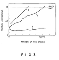
- Fig. 3 is a graph showing CSS durability of a disc.
- a recording medium has a structure in which magnetic layer 22 and lubricant layer 23 are sequentially formed on non-magnetic substrate 21.
- Non-magnetic substrate 21 is a flat rigid disc formed of an aluminum alloy plate or a glass plate having a thickness of several millimeters.
- Magnetic layer 22 is formed such that cobalt or a cobalt alloy is formed on substrate 21, by sputtering, a substantially flat continuous film.
- Layer 22 has a thickness in the order of several ten (hundred) to several hundred nm (thousand ⁇ ).
- Lubricant layer 23 contains carbon as its major component, and contains hydrogen or a halogen bonded to the carbon atoms which constitute the lubricant layer in the surface region.
- a layer consisting only of carbon must have a thickness of 10 nm (100 ⁇ ) or more.
- the total thickness of lubricant layer 23 is a maximum of 30 nm (300 ⁇ ), and the thickness of the improved surface region preferably falls within the range of 5 to 20 nm (50 to 200 ⁇ ).
- the manufacturing conditions of the recording medium are as follows: First, substrate 21 is placed on a rotary table of a sputtering apparatus. An initial vacuum pressure is set to be 133 ⁇ 10 ⁇ 6 Pa (1 ⁇ 10 ⁇ 6 Torr) or less, the table is rotated at a speed of 10 to 30 rpm, and a rare gas at a pressure of 665 ⁇ 10 ⁇ 3 Pa to 665 ⁇ 10 ⁇ 2 Pa (5 ⁇ 10 ⁇ 3 to 5 ⁇ 10 ⁇ 2 Torr) is introduced into the apparatus. Thus, a cobalt-alloy target is sputtered at room temperature, at a sputtering power of 0.3 to 2 kW. In this way, magnetic layer 22 is formed on substrate 21.
- a carbon target is sputtered to form a graphite layer consisting of only carbon.
- an additive gas such as a CH4 gas is added to the apparatus.
- the flow rate ratio of the additive gas and the rare gas is set to fall within the range of 1 : 9 to 1 : 1, and the total pressure of the gases is set to be 133 ⁇ 10 ⁇ 3 Pa to 1064 ⁇ 10 ⁇ 2 Pa (1 ⁇ 10 ⁇ 3 to 8 ⁇ 10 ⁇ 2 Torr) .
- the graphite layer containing hydrogen is formed on the carbon layer.
- smoothed layer 12 and underlayer 13 can be provided between substrate 11 and magnetic layer 14, and protective layer 15 can be provided between magnetic layer 14 and lubricant layer 16.
- Smoothed layer 12 is formed by plating on substrate 11, and its surface is mirror-polished so as to smooth the surface of the structure.
- Underlayer 13 is provided so as to improve the crystallographical orientation of magnetic layer 14.
- Protective layer 15 is adopted in order to protect magnetic layer 14 and to serve as part of the magnetic layer.
- the conditions for manufacturing the recording medium are as follows: First, smoothed layer 12 is formed on substrate 11 by plating, and the plated surface is finished to make it flat. Substrate 11 is then placed on a rotary table of a sputtering apparatus, and a metal target is sputtered under substantially the same conditions as those in the first embodiment, thereby forming underlayer 13, magnetic layer 14, and protective layer 15. Under substantially the same conditions as those in the first embodiment, a carbon target is sputtered to form lubricant layer 16 having an improved upper surface region.
- the present inventors changed the surface regions of lubricant layers 16 and 23 manufactured as described above, and performed the CCS test for media having lubricant layers whose thicknesses fall within the range of 5 to 50 nm (50 to 500 ⁇ ).
- the lubricant layer should preferably have a thickness in the range of 15 to 30 nm (150 to 300 ⁇ ).
- the improved surface region should preferably have a thickness falling within the range of 5 to 20 nm (50 to 200 ⁇ ).
- the improved surface region was subjected to composition analysis, and it was found that the media which achieved the best CSS test results contained 5 to 40 atomic % of H, F, Cl, or the like.
- Aluminum alloy substrate 11 having an outer diameter of 95 mm, an inner diameter of 25 mm, and a plate thickness of 1.27 mm was prepared.
- the above substrate was placed on a magnetron DC sputtering apparatus, and was sputtered, thereby to form under-layer 13, magnetic layer 14, and protective layer 15.
- the methods and conditions for forming these layers were as follows:
- the substrate chuck table used was capable of rotation or revolving in order that layers of uniform thicknesses and uniform magnetic characteristics could be obtained.
- the table was rotated at 10 rpm.
- a rare gas e.g., Ar gas
- Ar gas e.g., Ar gas
- sputtering was performed at room temperature, at an introduced Ar gas pressure of 532 x 10 ⁇ 2 Pa (4 x 10 ⁇ 2 Torr) , and at a sputtering power of 1kW.
- a 300 nm (3,000- ⁇ ) thick Cr layer was formed as underlayer 13 for improving the crystallographical orientation of the magnetic layer.
- a 50 nm (500- ⁇ ) thick Co-Ni layer as magnetic layer 14 and a 30 nm (300- ⁇ ) thick Co-Cr layer as protective layer 15 were formed thereon. Note that the Co-Cr protective layer also serves as a magnetic layer.
- a carbon target was sputtered to form a 70 nm (100- ⁇ ) thick carbon layer.
- a CH4 gas was introduced to the sputtering apparatus, the flow rate ratio of the Ar and CH4 gases was set to be 1 : 1, and the total combined pressure thereof was set to be 1064 x 10 ⁇ 2 Pa (8 x 10 ⁇ 2 Torr) .
- the carbon target was sputtered to form a 10 nm (100- ⁇ ) thick carbon layer containing the C-H bond on the previously formed carbon layer.
- lubricant layer 16 containing the C-H bond was formed on the surface layer.
- the resultant media were left to stand at a temperature of 85°C and at a relative humidity of 85% for 1,000 hours. No change in outer appearance was found, and no increase in surface defects was found. Thus, it could be confirmed that the recording medium possessed sufficiently satisfactory corrosion resistance.
- the CSS test result in relation to the magnetic recording medium of the present invention is represented by curve (A)
- the test result as regards a recording medium having a lubricant layer a part of which contains a C-H bond is represented by curve (B)
- the test result vis-a-vis a recording medium having a lubricant layer containing a C-H bond throughout it's entire region is represented by curve (C).
- Fig. 3 shows the relationship between the number of CSS cycles and the coefficient of friction.
- curve (B) relating to the conventional medium, the coefficient of friction exceeds 1.0 as an upper-limit, after about ten thousand head-falls in the course of a CSS test.
- curve (A) which relates to the present invention, almost no increase in the coefficient of friction is noted, even after ten thousand head-falls during a CSS test.
- Example 2 Following the same procedures as in Example 1, an anodized aluminum layer was formed, by anodizing, on aluminum alloy substrate 11, and its surface was polished to form hardened/smoothed layer 12. Thereafter, following the same procedures as in Example 1, underlayer 13, magnetic layer 14, protective layer 15, and lubricant layer 16 were formed. However, for protective layer 15, a 30 nm (300- ⁇ ) thick Cr film was used, and the thickness of magnetic layer 14 was 60 nm (600 ⁇ ). Upon formation of lubricant layer 16, a CF4 gas was used in place of the CH4 gas. For this reason, the presence of a C-F bond was found in lubricant layer 16. In this example, characteristics equivalent to or better than in Example 1 were confirmed.
- a glass plate having a thickness of 2 mm and a diameter of 8,89 cm (3.5 inches) and which had a flat surface was prepared as non-magnetic substrate 21.
- a 50 nm (500- ⁇ ) thick Co-Pt layer was formed directly on the substrate, as magnetic layer 22.
- a 15 nm (150- ⁇ ) thick carbon layer, as lubricant layer 23, obtained by sputtering a carbon target in Ar gas, and a 15 nm (150- ⁇ ) thick carbon layer, containing a C-H bond obtained by sputtering the carbon target while introducing a gas containing C2H6 at the same flow rate as that of the Ar gas, were formed on magnetic layer 22.
- the same characteristics as in the above examples were obtained.
Landscapes
- Chemical & Material Sciences (AREA)
- Inorganic Chemistry (AREA)
- Magnetic Record Carriers (AREA)
- Manufacturing Of Magnetic Record Carriers (AREA)
- Lubricants (AREA)
Claims (13)
- Magnetisches Aufzeichnungsmaterial, umfassend ein nicht-magnetisches Substrat (11, 21);
eine auf dem nicht-magnetischen Substrat (11, 21) gebildete magnetische Aufzeichnungsschicht (14, 22) und eine auf der magnetischen Aufzeichnungsschicht (14, 22) vorgesehene und Kohlenstoff als Hauptbestandteil enthaltende Gleitschicht (16, 23),
dadurch gekennzeichnet, daß an den Kohlenstoff der Gleitschicht (16, 23) lediglich in einem Oberflächenbereich dieser Gleitschicht (16, 23) mindestens ein Element aus der Gruppe Wasserstoff und Halogen gebunden ist. - Material nach Anspruch 1, dadurch gekennzeichnet, daß in dem Oberflächenbereich 5 - 40 Atom-% des Elements enthalten sind.
- Material nach Anspruch 1, dadurch gekennzeichnet, daß die Dicke des das betreffende Element enthaltenden Oberflächenbereichs in einen Bereich von 5 - 20 nm (50 - 200 A) fällt.
- Material nach Anspruch 1, dadurch gekennzeichnet, daß die Gesamtdicke der Gleitschicht (16, 23) in einen Bereich von 15 - 30 nm (150 - 300 Å) fällt.
- Material nach Anspruch 1, dadurch gekennzeichnet, daß die magnetische Schicht (14, 22) aus einem Kobaltmaterial gebildet ist.
- Material nach Anspruch 5, dadurch gekennzeichnet, daß zwischen der Gleitschicht (16, 23) und der magnetischen Schicht (14, 22) eine Schutzschicht (15) aus einer Co-Cr-Legierung vorgesehen ist.
- Material nach Anspruch 1, dadurch gekennzeichnet, daß das nicht-magnetische Substrat (11, 21) aus einer Platte aus einer Aluminiumlegierung oder einem Glas besteht.
- Verfahren zur Herstellung eines magnetischen Aufzeichnungsmaterials mit einer magnetischen Aufzeichnungsschicht durch Zerstäuben eines Kohlenstofftargets in einer Inertgasatmosphäre zur Bildung einer lediglich aus Graphit bestehenden Schicht auf einer magnetischen Aufzeichnungsschicht (14, 22) als zu behandelndem Material und Zerstäuben des Kohlenstofftargets unter Zufuhr eines Gases mit mindestens einem Element aus der Gruppe Wasserstoff und Halogen zur Bildung einer Graphitschicht mit einer Bindung zwischen Kohlenstoff und mindestens einem Element aus der Gruppe Wasserstoff und Halogen auf der aus lediglich aus Graphit bestehenden Schicht.
- Verfahren nach Anspruch 8, dadurch gekennzeichnet, daß das zugeführte Gas CH₄, C₂H₆ und/oder C₃H₈ umfaßt.
- Verfahren nach Anspruch 8, dadurch gekennzeichnet, daß das zugeführte Gas CF₄ umfaßt.
- Verfahren nach Anspruch 8, dadurch gekennzeichnet, daß das zugeführte Gas CCl₄ umfaßt.
- Verfahren nach Anspruch 8, dadurch gekennzeichnet, daß das zugeführte Gas CCl₂F₂ umfaßt.
- Verfahren nach Anspruch 8, dadurch gekennzeichnet, daß das zugeführte Gas CHF₃ umfaßt.
Applications Claiming Priority (2)
| Application Number | Priority Date | Filing Date | Title |
|---|---|---|---|
| JP134771/86 | 1986-06-12 | ||
| JP13477186 | 1986-06-12 |
Publications (3)
| Publication Number | Publication Date |
|---|---|
| EP0249216A2 EP0249216A2 (de) | 1987-12-16 |
| EP0249216A3 EP0249216A3 (en) | 1988-11-23 |
| EP0249216B1 true EP0249216B1 (de) | 1991-04-24 |
Family
ID=15136178
Family Applications (1)
| Application Number | Title | Priority Date | Filing Date |
|---|---|---|---|
| EP87108391A Expired - Lifetime EP0249216B1 (de) | 1986-06-12 | 1987-06-10 | Magnetisches Aufzeichnungsmedium und Verfahren zu dessen Herstellung |
Country Status (5)
| Country | Link |
|---|---|
| US (1) | US4820584A (de) |
| EP (1) | EP0249216B1 (de) |
| JP (1) | JPH07114016B2 (de) |
| KR (1) | KR910006150B1 (de) |
| DE (1) | DE3769517D1 (de) |
Families Citing this family (21)
| Publication number | Priority date | Publication date | Assignee | Title |
|---|---|---|---|---|
| US5118577A (en) * | 1988-03-10 | 1992-06-02 | Magnetic Peripherals Inc. | Plasma treatment for ceramic materials |
| US4863809A (en) | 1988-03-10 | 1989-09-05 | Magnetic Peripherals, Inc. | Surface treatment for sliders and carbon coated magnetic media |
| WO1990006575A1 (de) * | 1988-12-07 | 1990-06-14 | Siemens Aktiengesellschaft | Magnetisches aufzeichnungsmedium sowie verfahren zu dessen herstellung |
| US5045165A (en) * | 1990-02-01 | 1991-09-03 | Komag, Inc. | Method for sputtering a hydrogen-doped carbon protective film on a magnetic disk |
| US5119258A (en) * | 1990-02-06 | 1992-06-02 | Hmt Technology Corporation | Magnetic disc with low-friction glass substrate |
| US5030332A (en) * | 1990-04-19 | 1991-07-09 | Massachusetts Institute Of Technology | Method for making magnetic oxide precipitates |
| US5344706A (en) * | 1991-10-01 | 1994-09-06 | Carnegie Mellon University | Magnetic recording medium comprising an underlayer and a cobalt samarium amorphous magnetic layer having a SmCo5 crystalline interface with the underlayer |
| US5232791A (en) * | 1991-12-23 | 1993-08-03 | Minnesota Mining And Manufacturing Company | Magnetic recording medium having a carbon rich coating |
| US5286534A (en) * | 1991-12-23 | 1994-02-15 | Minnesota Mining And Manufacturing Company | Process for plasma deposition of a carbon rich coating |
| US5470447A (en) * | 1992-08-19 | 1995-11-28 | Stormedia, Inc. | Method for applying a protective coating on a magnetic recording head |
| US5525392A (en) * | 1992-12-10 | 1996-06-11 | International Business Machines Corporation | Magnetic recording medium having a fluorinated polymeric protective layer formed by an ion beam |
| EP0643385A3 (de) * | 1993-09-12 | 1996-01-17 | Fujitsu Ltd | Magnetischer Aufnahmeträger, Magnetkopf und magnetisches Aufzeichnungsgerät. |
| US5464667A (en) * | 1994-08-16 | 1995-11-07 | Minnesota Mining And Manufacturing Company | Jet plasma process and apparatus |
| US5693426A (en) * | 1994-09-29 | 1997-12-02 | Carnegie Mellon University | Magnetic recording medium with B2 structured underlayer and a cobalt-based magnetic layer |
| US5800931A (en) * | 1994-09-29 | 1998-09-01 | Carnegie Mellon University | Magnetic recording medium with a MgO sputter deposited seed layer |
| US6649277B1 (en) | 1994-09-29 | 2003-11-18 | Carnegie Mellon University | Structure for and method of making magnetic recording media |
| US5785825A (en) * | 1995-07-20 | 1998-07-28 | Seagate Technology, Inc. | Multi-phase overcoats for magnetic discs |
| US5942317A (en) * | 1997-01-31 | 1999-08-24 | International Business Machines Corporation | Hydrogenated carbon thin films |
| US6203898B1 (en) * | 1997-08-29 | 2001-03-20 | 3M Innovatave Properties Company | Article comprising a substrate having a silicone coating |
| US6432563B1 (en) | 2000-04-03 | 2002-08-13 | Carnegie Mellon University | Zinc enhanced hard disk media |
| US6596417B1 (en) | 2000-09-29 | 2003-07-22 | Carnegie Mellon University | Magnetic recording medium with a Ga3Pt5 structured underlayer and a cobalt-based magnetic layer |
Family Cites Families (18)
| Publication number | Priority date | Publication date | Assignee | Title |
|---|---|---|---|---|
| US4411963A (en) * | 1976-10-29 | 1983-10-25 | Aine Harry E | Thin film recording and method of making |
| JPS57135442A (en) * | 1981-02-16 | 1982-08-21 | Fuji Photo Film Co Ltd | Magnetic recording medium and its manufacture |
| JPH0766528B2 (ja) * | 1983-03-18 | 1995-07-19 | 富士写真フイルム株式会社 | 磁気記録媒体 |
| JPS6070521A (ja) * | 1983-09-28 | 1985-04-22 | Kanto Denka Kogyo Kk | 磁気記録媒体 |
| US4552820A (en) * | 1984-04-25 | 1985-11-12 | Lin Data Corporation | Disc media |
| JPS60253021A (ja) * | 1984-05-30 | 1985-12-13 | Victor Co Of Japan Ltd | 磁気記録媒体 |
| JPS60258727A (ja) * | 1984-06-06 | 1985-12-20 | Denki Kagaku Kogyo Kk | 磁気記憶媒体 |
| JPS6145412A (ja) * | 1984-08-09 | 1986-03-05 | Victor Co Of Japan Ltd | 磁気記録媒体製造法 |
| US4761334A (en) * | 1984-09-21 | 1988-08-02 | Kabushiki Kaisha Toshiba | Magnetic recording medium |
| DE3482168D1 (de) * | 1984-09-28 | 1990-06-13 | Japan Synthetic Rubber Co Ltd | Duenner kunststoffilm und ein solchen film enthaltender gegenstand. |
| KR890004256B1 (ko) * | 1984-09-29 | 1989-10-28 | 니뽕 빅터 가부시끼 가이샤 | 자기 기록 매체 |
| JPS61115232A (ja) * | 1984-11-10 | 1986-06-02 | Tdk Corp | 磁気記録媒体 |
| JPS61126627A (ja) * | 1984-11-26 | 1986-06-14 | Hitachi Ltd | 磁気記録媒体 |
| JPS61142525A (ja) * | 1984-12-13 | 1986-06-30 | Hitachi Metals Ltd | 磁気記録媒体 |
| JPH0610871B2 (ja) * | 1984-12-25 | 1994-02-09 | ティーディーケイ株式会社 | 磁気記録媒体 |
| JPS61208621A (ja) * | 1985-03-13 | 1986-09-17 | Sony Corp | 磁気デイスク |
| JPS6218624A (ja) * | 1985-07-18 | 1987-01-27 | Toshiba Corp | 磁気記録媒体 |
| US4647494A (en) * | 1985-10-31 | 1987-03-03 | International Business Machines Corporation | Silicon/carbon protection of metallic magnetic structures |
-
1987
- 1987-05-29 JP JP62131816A patent/JPH07114016B2/ja not_active Expired - Lifetime
- 1987-06-10 DE DE8787108391T patent/DE3769517D1/de not_active Expired - Lifetime
- 1987-06-10 US US07/060,388 patent/US4820584A/en not_active Expired - Lifetime
- 1987-06-10 EP EP87108391A patent/EP0249216B1/de not_active Expired - Lifetime
- 1987-06-11 KR KR1019870005902A patent/KR910006150B1/ko not_active Expired
Also Published As
| Publication number | Publication date |
|---|---|
| KR910006150B1 (ko) | 1991-08-16 |
| US4820584A (en) | 1989-04-11 |
| EP0249216A3 (en) | 1988-11-23 |
| KR880000921A (ko) | 1988-03-30 |
| EP0249216A2 (de) | 1987-12-16 |
| JPS63106919A (ja) | 1988-05-12 |
| DE3769517D1 (de) | 1991-05-29 |
| JPH07114016B2 (ja) | 1995-12-06 |
Similar Documents
| Publication | Publication Date | Title |
|---|---|---|
| EP0249216B1 (de) | Magnetisches Aufzeichnungsmedium und Verfahren zu dessen Herstellung | |
| EP0709830A2 (de) | Magnetisches Aufzeichnungsmedium, Verfahren zu seiner Herstellung sowie magnetische Aufnahmegeräte | |
| US4664976A (en) | Magnetic recording medium comprising a protective carbon nitride layer on the surface thereof | |
| JP3018762B2 (ja) | 磁気記録媒体およびその製造方法 | |
| US6238780B1 (en) | Magnetic recording medium comprising multilayered carbon-containing protective overcoats | |
| US5118564A (en) | Longitudinal magnetic recording media with fine grain crystal magnetic layer | |
| US4680218A (en) | Magnetic recording medium | |
| EP0538887A1 (de) | Magnetisches Aufzeichnungsmedium und Methode zur Untersuchung des magnetischen Aufzeichnungsmediums | |
| EP0438177B1 (de) | Magnetische Aufzeichnungsplatte | |
| US4837080A (en) | Magnetic recording mediums for high density recording comprising an improved structure of a magnetic layer | |
| EP0274437B1 (de) | Magnetischer Aufzeichnungsträger | |
| JPH0770037B2 (ja) | 面内磁化記録用金属薄膜型磁気記録媒体 | |
| JPS60209929A (ja) | 磁気記憶体およびその製造方法 | |
| JP2732153B2 (ja) | 金属薄膜型磁気記録媒体 | |
| JP3038888B2 (ja) | 磁気ディスク | |
| JPH0513333B2 (de) | ||
| JPH04137217A (ja) | 磁気特性に優れた磁気ディスクの製造法 | |
| JPH0554368A (ja) | 磁気記録媒体 | |
| JPH0223522A (ja) | 磁気記録媒体の製造方法 | |
| JPH0684168A (ja) | 磁気記録媒体 | |
| JPH0268712A (ja) | 薄膜型磁気記録媒体 | |
| Hardeman | New materials in rigid disks | |
| JPS62252518A (ja) | 磁気記録媒体およびその製造方法 | |
| JPH0770050B2 (ja) | 磁気記録媒体 | |
| JPH03102616A (ja) | 磁気記録媒体 |
Legal Events
| Date | Code | Title | Description |
|---|---|---|---|
| PUAI | Public reference made under article 153(3) epc to a published international application that has entered the european phase |
Free format text: ORIGINAL CODE: 0009012 |
|
| 17P | Request for examination filed |
Effective date: 19870707 |
|
| AK | Designated contracting states |
Kind code of ref document: A2 Designated state(s): DE FR GB |
|
| PUAL | Search report despatched |
Free format text: ORIGINAL CODE: 0009013 |
|
| AK | Designated contracting states |
Kind code of ref document: A3 Designated state(s): DE FR GB |
|
| 17Q | First examination report despatched |
Effective date: 19900208 |
|
| GRAA | (expected) grant |
Free format text: ORIGINAL CODE: 0009210 |
|
| AK | Designated contracting states |
Kind code of ref document: B1 Designated state(s): DE FR GB |
|
| REF | Corresponds to: |
Ref document number: 3769517 Country of ref document: DE Date of ref document: 19910529 |
|
| ET | Fr: translation filed | ||
| PLBE | No opposition filed within time limit |
Free format text: ORIGINAL CODE: 0009261 |
|
| STAA | Information on the status of an ep patent application or granted ep patent |
Free format text: STATUS: NO OPPOSITION FILED WITHIN TIME LIMIT |
|
| 26N | No opposition filed | ||
| REG | Reference to a national code |
Ref country code: GB Ref legal event code: 746 Effective date: 19981010 |
|
| REG | Reference to a national code |
Ref country code: FR Ref legal event code: D6 |
|
| PGFP | Annual fee paid to national office [announced via postgrant information from national office to epo] |
Ref country code: DE Payment date: 20000605 Year of fee payment: 14 |
|
| PGFP | Annual fee paid to national office [announced via postgrant information from national office to epo] |
Ref country code: GB Payment date: 20000607 Year of fee payment: 14 |
|
| PGFP | Annual fee paid to national office [announced via postgrant information from national office to epo] |
Ref country code: FR Payment date: 20000612 Year of fee payment: 14 |
|
| PG25 | Lapsed in a contracting state [announced via postgrant information from national office to epo] |
Ref country code: GB Free format text: LAPSE BECAUSE OF NON-PAYMENT OF DUE FEES Effective date: 20010610 |
|
| GBPC | Gb: european patent ceased through non-payment of renewal fee |
Effective date: 20010610 |
|
| PG25 | Lapsed in a contracting state [announced via postgrant information from national office to epo] |
Ref country code: FR Free format text: LAPSE BECAUSE OF NON-PAYMENT OF DUE FEES Effective date: 20020228 |
|
| PG25 | Lapsed in a contracting state [announced via postgrant information from national office to epo] |
Ref country code: DE Free format text: LAPSE BECAUSE OF NON-PAYMENT OF DUE FEES Effective date: 20020403 |