EP0248367A2 - Kontaktierungsband für einen elektrisch leitenden Belag - Google Patents
Kontaktierungsband für einen elektrisch leitenden Belag Download PDFInfo
- Publication number
- EP0248367A2 EP0248367A2 EP87107852A EP87107852A EP0248367A2 EP 0248367 A2 EP0248367 A2 EP 0248367A2 EP 87107852 A EP87107852 A EP 87107852A EP 87107852 A EP87107852 A EP 87107852A EP 0248367 A2 EP0248367 A2 EP 0248367A2
- Authority
- EP
- European Patent Office
- Prior art keywords
- band
- copper wires
- picture tube
- rubber
- threads
- Prior art date
- Legal status (The legal status is an assumption and is not a legal conclusion. Google has not performed a legal analysis and makes no representation as to the accuracy of the status listed.)
- Granted
Links
- 239000012799 electrically-conductive coating Substances 0.000 title claims 2
- RYGMFSIKBFXOCR-UHFFFAOYSA-N Copper Chemical compound [Cu] RYGMFSIKBFXOCR-UHFFFAOYSA-N 0.000 claims abstract description 28
- 229910052802 copper Inorganic materials 0.000 claims abstract description 22
- 239000010949 copper Substances 0.000 claims abstract description 22
- 239000004753 textile Substances 0.000 claims abstract description 17
- 239000004744 fabric Substances 0.000 claims abstract description 3
- OKTJSMMVPCPJKN-UHFFFAOYSA-N Carbon Chemical compound [C] OKTJSMMVPCPJKN-UHFFFAOYSA-N 0.000 claims description 7
- 239000011248 coating agent Substances 0.000 claims description 7
- 238000000576 coating method Methods 0.000 claims description 7
- 239000002759 woven fabric Substances 0.000 claims description 2
- 229920002334 Spandex Polymers 0.000 claims 1
- 239000004033 plastic Substances 0.000 claims 1
- 239000004759 spandex Substances 0.000 claims 1
- 239000000463 material Substances 0.000 description 5
- 239000003990 capacitor Substances 0.000 description 3
- 238000004519 manufacturing process Methods 0.000 description 3
- 238000011161 development Methods 0.000 description 2
- 230000018109 developmental process Effects 0.000 description 2
- 230000007547 defect Effects 0.000 description 1
- 230000000694 effects Effects 0.000 description 1
- 239000011521 glass Substances 0.000 description 1
- 238000003780 insertion Methods 0.000 description 1
- 230000037431 insertion Effects 0.000 description 1
- 238000009940 knitting Methods 0.000 description 1
- 239000002184 metal Substances 0.000 description 1
- 229910052751 metal Inorganic materials 0.000 description 1
- 238000000034 method Methods 0.000 description 1
- 230000000717 retained effect Effects 0.000 description 1
- 238000005476 soldering Methods 0.000 description 1
- 238000009941 weaving Methods 0.000 description 1
Images
Classifications
-
- H—ELECTRICITY
- H04—ELECTRIC COMMUNICATION TECHNIQUE
- H04N—PICTORIAL COMMUNICATION, e.g. TELEVISION
- H04N9/00—Details of colour television systems
- H04N9/12—Picture reproducers
- H04N9/16—Picture reproducers using cathode ray tubes
- H04N9/29—Picture reproducers using cathode ray tubes using demagnetisation or compensation of external magnetic fields
-
- H—ELECTRICITY
- H01—ELECTRIC ELEMENTS
- H01J—ELECTRIC DISCHARGE TUBES OR DISCHARGE LAMPS
- H01J29/00—Details of cathode-ray tubes or of electron-beam tubes of the types covered by group H01J31/00
- H01J29/92—Means forming part of the tube for the purpose of providing electrical connection to it
Definitions
- a contacting band is the so-called ground band on the picture tube of a television receiver.
- the picture tube contains a vapor-deposited conductive coating, the so-called Aquadag coating, which together with the anode forms a capacitor within the picture tube, which acts as a filter capacitor for the high voltage.
- This Aquadag covering must be grounded with a contact strip, a so-called earth strap, which is applied over a greater length.
- the ground strap is connected at one point to a line that leads to a grounding point of the device chassis or picture tube board.
- the invention has for its object to reduce the costs for the contacting tape and for its attachment to the conductive covering.
- the rubber-elastic band is preferably a self-contained endless band, that is to say similar to a rubber ring that only needs to be wrapped around peg-like projections on the picture tube.
- One or more springs to achieve tight support on the conductive covering are not required because the required spring action is generated by the tape itself.
- the necessary spring action is therefore integrated into the contacting band in the form of a very large number of small springs. Assembly is considerably simplified because there is no need to manually hang the springs in the contact strip's eyelets or to hang the springs in the eyelets on the component that supports the covering.
- the woven fabric of the band additionally consists of textile threads.
- These textile threads can replace part of the copper wires and together with them they can be made, woven, crocheted or knitted.
- Replacing the copper wires with textile threads saves weight and costs due to the material price of the strip itself, but it also makes production easier.
- the latter circumstance is based on the fact that the conventional bobbin-making, weaving or knitting machines suitable for the production of the tapes can only accommodate a relatively short length of copper wire on their spindles. This is due to the in ver Substantially higher mass of copper than textile material, for which the stability of the receiving device is not dimensioned for a comparable length and for which wire breaks could easily occur due to the inertial forces during wire removal. Smaller spindles are therefore used, which, however, require more frequent replacement combined with a temporary machine downtime.
- the partial replacement of copper wires with textile threads reduces both the need for copper wire and thus the exchange rate of the copper wire spindles, as well as the machine wear, which is lower when processing textile threads than when processing copper wire.
- the proportion of about 20 to 50% copper wires in the entire fabric part formed from copper wires and textile threads ensures that the electrical conductivity is maintained for the intended purpose even if some of the copper threads are caused by manufacturing defects, material fatigue or improper use Break treatment.
- the invention can be used particularly advantageously for the ground strap in the picture tube of a television receiver, which effects the necessary grounding of the so-called Aquadag coating on the outer surface of the picture tube.
- the costs for the relatively expensive ground strap and for the manual processes, the so-called handling, are considerably reduced.
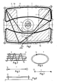
- Fig. 1 shows a picture tube 1, which is surrounded by the clamping band 2 made of sheet metal. Shown are the tube neck 3 and the Aquadag coating 4 evaporated onto the picture tube 1, which together with a similar coating applied inside the picture tube forms the high-voltage capacitor.
- the two demagnetizing coils 5a and 5b are provided on the picture tube 1 and are suspended in a plurality of hooks 6 on the tensioning band 2.
- the necessary contacting of the large-area Aquadag covering 4 for grounding takes place with the endless, that is to say closed ring-like, rubber-elastic band 7.
- the band 7 is stretched around projections 8 and hooks on the fastening clips 6 for the demagnetizing coil 5a and 5b .
- a total of four such mounting brackets 6 serving to hold the demagnetizing coil 5a, 5b on the frame of the screen also serve as mounting points together with the projections 8 for holding the band 7.
- the stretching of the band 7 results in the necessary resilient and tight system of the band 7 on the covering 4.
- the band 7 is, for example made of a material that has an elasticity in the order of 90-120% without substantial residual expansion.
- the projections, pins or hooks used to hold the band 7 can be arranged directly on the picture tube or on the deflection unit placed on the neck 3.
- annular band 7 the previously required separate springs in the path of the band 7 are no longer required. This also eliminates the need to hook the springs into the band and to hook the springs into corresponding hooks on the picture tube, since the stretchable band 7 only needs to be put around the pins, projections or hooks described.
- the line 10 from an insulated copper wire is fastened with the clamp 9, which connects the band 7 to earth potential of the receiver chassis or picture tube board.
- the clamp 9 which connects the band 7 to earth potential of the receiver chassis or picture tube board.
- the band 7 has an approximately triangular shape.
- the band 7 is held between the lower left and the upper right corner of the screen on the deflection unit, not shown, and may therefore have a curved course.
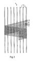
- the band 7 consists of longitudinally running rubber threads 11, which are pierced by a large number of copper wires 12.
- the rubber threads 11 stretch in the longitudinal direction.
- the copper wires 12 cannot stretch and are practically stretched by reducing the width of the band 7, i.e. the geometric length of the meandering shape formed is lengthened in the longitudinal direction.
- the band 7 is provided with textile threads 17 in addition to the longitudinal rubber threads 11 and the copper wires 12.
- the Copper wires 12 continue to form the conductive surface, while the textile threads 17 contribute to the mechanical flexibility and elasticity.
- the textile threads 17 stretch practically no more than the copper wires 12 but are only stretched by reducing the width of the band 7.
- the material cost share is also lower due to the smaller copper wire share.
- the proportion of copper wires 12 being around 3 to 5. In this way it is ensured that even in the event of a wire break, a reserve is still available and the functionality of the belt 7 is retained.
- the copper wires 12 and textile threads 17 are expediently knitted in parallel and distributed evenly next to one another.
- the band 7, e.g. as in Fig. 2 or 3 is constructed as a self-contained endless ring and can be placed around the pin 8 by a light handle according to FIG. 1.
- An initially straight band 7 is preferably connected at a point 15 to form a ring by a clip or another so-called clasp.
- the band 7 is provided with two ends, each containing an eyelet 14.
- the band 7 with the eyelets 14 can be placed on two pins 8 and placed around a third pin 8 on the picture tube 1.
- the band 7 is impaled on pins 13 arranged on the picture tube, in that the pointed pin 13 penetrates into the braid according to FIGS. 2 or 3 with little deformation.
- the band 7 is provided at its ends with two knots 16 with which the band 7 e.g. can be hung in eyelets of fasteners on the picture tube 1.
Landscapes
- Engineering & Computer Science (AREA)
- Multimedia (AREA)
- Signal Processing (AREA)
- Shielding Devices Or Components To Electric Or Magnetic Fields (AREA)
- Vessels, Lead-In Wires, Accessory Apparatuses For Cathode-Ray Tubes (AREA)
Abstract
Description
- Bei elektrischen oder elektronischen Bauteilen besteht oft die Aufgabe, einen elektrisch leitenden Belag mit einem Kontaktierungsband zu kontaktieren, um den Belag mit einem Bezugspotential, insbesondere Erde zu verbinden. Ein solches Band ist deshalb notwendig, weil z.B. ein auf eine Glasfläche aufgespritzter Abschirmungsbelag nicht durch Lötung o.dgl. kontaktiert werden kann und außerdem wegen seiner Hochohmigkeit eine Kontaktierung über eine größere Länge bzw. Fläche fordert.
- Ein Beispiel für ein derartiges Kontaktierungsband ist das sogenannte Masseband an der Bildröhre eines Fernsehempfängers. Die Bildröhre enthält außen am konusförmigen Teil einen aufgedampften leitenden Belag, den sogenannten Aquadag-Belag, der zusammen mit der Anode innerhalb der Bildröhre einen Kondensator bildet, der als Siebkondensator für die Hochspannung wirkt. Dieser Aquadag-Belag muß mit einem über eine größere Länge anliegenden Kontaktierungsband, einen sogenannten Masseband geerdet werden.
- Dabei ist es bekannt, ein aus einem Geflecht bestehendes Masseband um verschiedene Stützpunkte am äußeren Rand der Bildröhre herumzulegen und unter Einfügung von einer oder mehreren Federn so zu spannen, daß es stramm an dem Aquadag-Belag anliegt und die gewünschte großflächige Kontaktierung bewirkt. Das Masseband ist an einer Stelle mit einer Leitung verbunden, die zu einem Erdungspunkt des Gerätechassis oder Bildröhrenplatine führt.
- Die Kosten für das genannte Masseband und die Anbringung auf/an der Bildröhre sind relativ hoch, zumal das Masseband nicht automatisch angebracht werden kann, sondern manuell an den einzelnen Stützpunkten befestigt werden muß.
- Der Erfindung liegt die Aufgabe zugrunde, die Kosten für das Kontaktierungsband und für dessen Anbringung an dem leitenden Belag zu verringern.
- Diese Aufgabe wird durch die im Anspruch 1 beschriebene Erfindung gelöst. Vorteilhafte Weiterbildungen der Erfindung sind in den Unteransprüchen beschrieben.
- Bei der erfindungsgemäßen Lösung entfallen weitestgehend bisher benötigte Haken und Federn. Das gummielastische Band ist vorzugsweise ein in sich geschlossenes endloses Band, also ähnlich wie ein Gummiring, das lediglich um zapfenartige Vorsprünge an der Bildröhre herumgelegt zu werden braucht. Eine oder mehrere Federn zur Erzielung der strammen Auflage auf dem leitenden Belag werden nicht benötigt, weil die erforderliche Federwirkung durch das Band selbst erzeugt wird. Die notwendige Federwirkung ist also in Form einer sehr großen Zahl kleiner Federn in das Kontaktierungsband hinein integriert. Die Montage wird wesentlich vereinfacht, weil das manuelle Einhängen der Federn in Ösen des Kontaktierungsbandes sowie das Einhängen der Federn in Ösen an dem den Belag tragenden Bauteil entfallen.
- Bei einer vorteilhaften Weiterbildung der Erfindung besteht das Gewebegeflecht des Bandes zusätzlich aus Textilfäden. Diese Textilfäden können einen Teil der Kupferdrähte ersetzen und zusammen mit diesen geklöppelt, gewebt, gehäkelt oder gestrickt werden. Der Ersatz der Kupferdrähte durch Textilfäden bringt einmal eine Gewichts- und Kostenersparnis auf Grund des Materialpreises bei dem Band selbst, zum anderen erleichtert es aber auch die Fertigung. Der letztgenannte Umstand beruht darauf, daß die für die Herstellung der Bänder geeigneten üblichen Klöppel-, Web- oder Strickmaschinen nur eine verhältnismäßig geringe Länge Kupferdraht auf ihren Spindeln aufnehmen können. Dies liegt an der im Ver gleich zu textilem Material wesentlichen höheren Masse von Kupfer, für die bei vergleichbarer Länge die Stabilität der Aufnahmevorrichtung nicht bemessen ist und bei der außerdem durch die Trägheitkräfte bei der Drahtentnahme leicht Drahtbrüche auftreten könnten. Es werden deshalb kleinere Spindeln verwendet, die aber ein häufigeres Auswechseln, verbunden mit einem vorrübergehenden Maschinenstillstand erforderlich machen.
- Der teilweise Ersatz der Kupferdrähte durch Textilfäden vermindert sowohl den Bedarf an Kupferdraht und damit die Austauschrate der Kupferdrahtspindeln als auch zusätzlich den Maschinenverschleiß, der bei der Verarbeitung von Textilfäden geringer als bei der Verarbeitung von Kupferdraht ist. Der gemäß einer praktischen Ausführungsform getroffene Anteil von etwa 20 bis 50% Kupferdrähte an dem gesamten aus Kupferdrähten und Textilfäden gebildeten Gewebeteil sorgt dafür, daß die elektrische Leitfähigkeit für den vorgesehenen Zweck auch dann erhalten bleibt, wenn ein Teil der Kupferfäden durch Fertigungsfehler, Materialermüdung oder unsachgemäße Behandlung brechen.
- Die Erfindung ist besonders vorteilhaft anwendbar für däs Masseband bei der Bildröhre eines Fernsehempfängers, das die notwendige Erdung des sogenannten Aquadag-Belages auf der äußeren Oberfläche der Bildröhre bewirkt. Dort werden insbesondere die Kosten für das relativ teure Masseband sowie die für die manuellen Vorgänge, des sogenannten Handling, beträchtlich verringert.
- Die Erfindung wird in folgenden anhand der Zeichnung am Beispiel der Bildröhre des Fernsehempfängers erläutert. Darin zeigen
- Fig. 1 die Bildröhre eines Fernsehempfängers mit dem erfindungsgemäßen Masseband,
- Fig. 2 im Prinzip den Aufbau eines erfindungsgemäßen Massebandes,
- Fig. 3 eine bevorzugte Ausgestaltung eines erfindungsgemäßen Massebandes und
- Fig. 4-7 verschiedene Formen des Massebandes.
- Fig. 1 zeigt eine Bildröhre 1, die von dem Spannband 2 aus Blech umgeben ist. Dargestellt sind der Röhrenhals 3 und der auf die Bildröhre 1 aufgedampfte Aquadag-Belag 4, der zusammen mit einem im Inneren der Bildröhre aufgebrachten ähnlichen Belag den Hochspannungskondensator bildet. An der Bildröhre 1 sind die beiden Entmagnetisierungspulen 5a und 5b vorgesehen, die in eine Vielzahl von Haken 6 an dem Spannband 2 eingehängt sind.
- Die notwendige Kontaktierung des großflächigen Aquadag-Belages 4 für die Erdung erfolgt mit dem endlosen, also in sich geschlossenen ringartigen, gummielastischen Band 7. Das Band 7 ist unter Dehnung um Vorsprünge 8 und um Haken an den Befestigungsklammern 6 für die Entmagnetisierungsspule 5a und 5b herumgelegt. In Fig. 1 dienen insgesamt vier derartige zur Halterung der Entmagnetisierungsspule 5a, 5b dienende Befestigungsklammern 6 am Rahmen des Bildschirms zusätzlich als Aufnahmepunkte zusammen mit den Vorsprüngen 8 zur Halterung des Bandes 7. Durch die Dehnung des Bandes 7 ergibt sich die notwendige ferdernde und stramme Anlage des Bandes 7 an dem Belag 4. Das Band 7 besteht z.B. aus einem Material, das eine Dehungsfähigkeit ohne wesentliche Restdehnung in der Größenordnung von 90 - 120% aufweist.
- Grundsätzlich können die zur Aufnahme des Bandes 7 dienenden Vorsprünge, Zapfen oder Haken je nach ihrer Lage oder je nach dem Aufbau der Bildröhre an dem Spannband 2, unmittelbar an der Bildröhre oder an der auf den Hals 3 aufgesetzten Ablenkeinheit angeordnet sein. Durch das in sich geschlosse ne, ringförmige Band 7 werden also die bisher benötigten getrennten Federn im Weg des Bandes 7 nicht mehr benötigt. Damit entfällt auch das Einhängen der Federn in das Band sowie das Einhängen der Federn in entsprechende Haken an der Bildröhre, da das dehnbare Band 7 lediglich um die beschriebenen Zapfen, Vorsprünge oder Haken herumgelegt zu werden braucht.
- An dem Band 7 ist mit der Klemme 9 die Leitung 10 aus einer isolierten Kupferlitze befestigt, die das Band 7 mit Erdpotential des Empfängerchassis oder Bildrohrplatine verbindet. Im einfachsten Fall sind insgesamt nur drei Zapfen 8 oder sonstige Aufnahmemittel für das Band 7 vorgesehen, z.B. zwei oben links und rechts und eins unten in der Mitte, so daß das Band 7 einen etwa dreieckförmigen Verlauf hat. In Fig. 1 ist das Band 7 zwischen der unteren linken und der oberen rechten Ecke des Bildschirms an der nicht dargestellten Ablenkeinheit gehaltert und hat dadurch gegebenenfalls einen gekrümmten Verlauf.
- Gemäß Fig. 2 besteht das Band 7 aus in Längsrichtung verlaufenden Gummifäden 11, die von einer Vielzahl von Kupferdrähten 12 durchschossen sind. Die Kupferdrähte 12, die unisoliert und verzinnt sind, bilden für das Band 7 die erforderliche leitende Oberfläche. Bei der Dehnung des Bandes 7 dehnen sich die Gummifäden 11 in Längsrichtung. Die Kupferdrähte 12 können sich nicht dehnen und werden durch die Verringerung der Breite des Bandes 7 praktisch gestreckt, d.h. die geometrische Länge der gebildeten mäanderförmigen Form wird in Längsrichtung verlängert.
- Bei der Ausgestaltung in Fig. 3 ist das Band 7 zusätzlich zu den in Längsrichtung verlaufenden Gummifäden 11 und den Kupferdrähten 12 mit Textilfäden 17 versehen. Die Kupferdrähte 12 bilden weiterhin die leitende Oberfläche, während die Textilfäden 17 zur mechanischen Flexibilität und Elastizität beitragen. Bei Dehnung des Bandes 7 in Längsrichtung dehnen sich die Textilfäden 17 praktisch ebensowenig wie die Kupferdrähte 12 sondern werden lediglich durch Verringerung der Breite des Bandes 7 gestreckt. Neben einem geringeren Gewicht und einer höheren Flexibilität ist auch der Materialkostenanteil auf Grund des kleineren Kupferdrahtanteils geringer. Vorzugsweise werden etwa zwischen 11 und 13 Fäden verwendet, wobei der Anteil der Kupferdrähte 12 etwa bei 3 bis 5 liegt. Auf diese Weise ist sichergestellt, daß auch bei einem eventuellen Drahtbruch noch eine Reserve vorhanden ist und die Funktionstüchtigkeit des Bandes 7 erhalten bleibt. Zweckmäßig sind die Kupferdrähte 12 und Textilfäden 17 parallel verstrickt und gleichmäßig nebeneinander verteilt.
- Gemäß Fig. 4 ist das Band 7, das z.B. wie in Fig. 2 oder 3 aufgebaut ist, als in sich geschlossener endloser Ring ausgebildet und kann gemäß Fig. 1 durch eine leichte Handhabe um die Zapfen 8 herumgelegt werden. Vorzugsweise ist ein zunächst gerades Band 7 an einer Stelle 15 durch eine Klammer oder eine sonstige sogenannte Schließe zu einem Ring verbunden.
- In Fig. 5 ist das Band 7 mit zwei Enden versehen, die je eine öse 14 enthalten. Dadurch kann beispielsweise das Band 7 mit den ösen 14 an zwei Zapfen 8 aufgesetzt und um einen dritten Zapfen 8 an der Bildröhre 1 herumgelegt werden.
- Gemäß Fig. 6 ist das Band 7 auf an der Bildröhre angeordnete Zapfen 13 aufgespießt, indem der spitz ausgebildete Zapfen 13 unter geringer Verformung in das Geflecht gemäß Fig. 2 oder 3 eindringt.
- In Fig. 7 ist statt der Ösen 14 in Fig. 5 das Band 7 an seinen Enden mit zwei Knoten 16 versehen, mit denen das Band 7 z.B. in Ösen von Befestigungsmitteln an der Bildröhre 1 eingehängt werden kann.
Claims (14)
dadurch gekennzeichnet, daß das Kontaktierungsband als gummielastisches Band (7) mit elektrisch leitender, unisolierter Oberfläche ausgebildet ist.
dadurch gekennzeichnet, daß das Band (7) unter Dehnung an verschiedenen Vorsprüngen (6,8) an der Bildröhre (1) eingehängt ist und ohne Verwendung gesonderter Federn stramm auf dem Aquadag-Belag (4) der Bildröhre (1) aufliegt.
Priority Applications (1)
| Application Number | Priority Date | Filing Date | Title |
|---|---|---|---|
| AT87107852T ATE64235T1 (de) | 1986-06-05 | 1987-05-30 | Kontaktierungsband fuer einen elektrisch leitenden belag. |
Applications Claiming Priority (4)
| Application Number | Priority Date | Filing Date | Title |
|---|---|---|---|
| DE19863618948 DE3618948A1 (de) | 1986-06-05 | 1986-06-05 | Kontaktierungsband fuer einen elektrisch leitenden belag |
| DE3618948 | 1986-06-05 | ||
| DE3715474 | 1987-05-08 | ||
| DE19873715474 DE3715474A1 (de) | 1987-05-08 | 1987-05-08 | Kontaktierungsband fuer einen elektrisch leitenden belag |
Publications (3)
| Publication Number | Publication Date |
|---|---|
| EP0248367A2 true EP0248367A2 (de) | 1987-12-09 |
| EP0248367A3 EP0248367A3 (en) | 1988-12-21 |
| EP0248367B1 EP0248367B1 (de) | 1991-06-05 |
Family
ID=25844378
Family Applications (1)
| Application Number | Title | Priority Date | Filing Date |
|---|---|---|---|
| EP87107852A Expired - Lifetime EP0248367B1 (de) | 1986-06-05 | 1987-05-30 | Kontaktierungsband für einen elektrisch leitenden Belag |
Country Status (6)
| Country | Link |
|---|---|
| EP (1) | EP0248367B1 (de) |
| JP (1) | JPH0821342B2 (de) |
| KR (1) | KR910009855B1 (de) |
| DE (1) | DE3770524D1 (de) |
| ES (1) | ES2022834B3 (de) |
| GR (1) | GR3002425T3 (de) |
Family Cites Families (2)
| Publication number | Priority date | Publication date | Assignee | Title |
|---|---|---|---|---|
| US3014087A (en) * | 1957-12-17 | 1961-12-19 | Kaplan Philip | Extensible electric cables |
| US3996491A (en) * | 1974-08-26 | 1976-12-07 | Gte Sylvania Incorporated | External connective means for a cathode ray tube |
-
1987
- 1987-05-28 JP JP62130055A patent/JPH0821342B2/ja not_active Expired - Lifetime
- 1987-05-30 ES ES87107852T patent/ES2022834B3/es not_active Expired - Lifetime
- 1987-05-30 EP EP87107852A patent/EP0248367B1/de not_active Expired - Lifetime
- 1987-05-30 DE DE8787107852T patent/DE3770524D1/de not_active Expired - Lifetime
- 1987-06-05 KR KR1019870005700A patent/KR910009855B1/ko not_active Expired
-
1991
- 1991-08-02 GR GR91401111T patent/GR3002425T3/el unknown
Also Published As
| Publication number | Publication date |
|---|---|
| KR880001162A (ko) | 1988-03-31 |
| DE3770524D1 (de) | 1991-07-11 |
| KR910009855B1 (ko) | 1991-11-30 |
| EP0248367A3 (en) | 1988-12-21 |
| ES2022834B3 (es) | 1991-12-16 |
| JPS63259944A (ja) | 1988-10-27 |
| JPH0821342B2 (ja) | 1996-03-04 |
| GR3002425T3 (en) | 1992-12-30 |
| EP0248367B1 (de) | 1991-06-05 |
Similar Documents
| Publication | Publication Date | Title |
|---|---|---|
| DE3636128C2 (de) | ||
| DE2225755C3 (de) | Gurtband | |
| DE20209219U1 (de) | Gestrick | |
| DE1509424A1 (de) | Leiterschnur fuer Jalousien | |
| EP0248367B1 (de) | Kontaktierungsband für einen elektrisch leitenden Belag | |
| DE2155416B2 (de) | An einem pfahl zu befestigende vorrichtung zum halten eines oder mehrerer gespannter draehte | |
| DE3513325A1 (de) | Haftverschluss | |
| DE2828936C2 (de) | Band zur therapeutischen Behandlung | |
| DE3230667A1 (de) | Passiver ionisator | |
| DE202013100966U1 (de) | Dreidimensionale, leitfähige Gewebeanordnung | |
| DE3715474A1 (de) | Kontaktierungsband fuer einen elektrisch leitenden belag | |
| DE102006036405A1 (de) | Textiler Leiter | |
| DE102016116028A1 (de) | Verfahren zum Fixieren von elektronischen Bauelementen auf einem flexiblen, insbesondere textilen Flächengebilde | |
| DE3618948A1 (de) | Kontaktierungsband fuer einen elektrisch leitenden belag | |
| WO1998023190A2 (de) | Sitzüberzug | |
| DE3722365A1 (de) | Einrichtung zum befestigen von doppelfederzinken | |
| DE2737824C2 (de) | Staubkante zur strömungstechnischen Entstaubung an Mähdreschern | |
| DE1110102B (de) | Verfahren zur Herstellung eines gewebten Reissverschlusses | |
| DE2337530A1 (de) | Jacquardwebelitze mit einem elastischen rueckzugfaden | |
| DE432386C (de) | Antenne fuer drahtlose Anlagen | |
| DE929377C (de) | Verfahren zur Herstellung von Stromanschluss- und Halteteilen an Widerstandsstaeben | |
| DE4441013C2 (de) | Vorrichtung zur Herstellung einer Masseverbindung mit der Aquadierung einer Bildröhre | |
| DE281631C (de) | ||
| DE4430298C1 (de) | Elektroweidezaunband | |
| DE8127979U1 (de) | Elastisches flockgarn |
Legal Events
| Date | Code | Title | Description |
|---|---|---|---|
| PUAI | Public reference made under article 153(3) epc to a published international application that has entered the european phase |
Free format text: ORIGINAL CODE: 0009012 |
|
| AK | Designated contracting states |
Kind code of ref document: A2 Designated state(s): AT BE CH DE ES FR GB GR IT LI LU NL SE |
|
| PUAL | Search report despatched |
Free format text: ORIGINAL CODE: 0009013 |
|
| AK | Designated contracting states |
Kind code of ref document: A3 Designated state(s): AT BE CH DE ES FR GB GR IT LI LU NL SE |
|
| 17P | Request for examination filed |
Effective date: 19890415 |
|
| 17Q | First examination report despatched |
Effective date: 19901114 |
|
| GRAA | (expected) grant |
Free format text: ORIGINAL CODE: 0009210 |
|
| AK | Designated contracting states |
Kind code of ref document: B1 Designated state(s): AT BE CH DE ES FR GB GR IT LI LU NL SE |
|
| REF | Corresponds to: |
Ref document number: 64235 Country of ref document: AT Date of ref document: 19910615 Kind code of ref document: T |
|
| ITF | It: translation for a ep patent filed | ||
| REF | Corresponds to: |
Ref document number: 3770524 Country of ref document: DE Date of ref document: 19910711 |
|
| ET | Fr: translation filed | ||
| GBT | Gb: translation of ep patent filed (gb section 77(6)(a)/1977) | ||
| PLBE | No opposition filed within time limit |
Free format text: ORIGINAL CODE: 0009261 |
|
| STAA | Information on the status of an ep patent application or granted ep patent |
Free format text: STATUS: NO OPPOSITION FILED WITHIN TIME LIMIT |
|
| PGFP | Annual fee paid to national office [announced via postgrant information from national office to epo] |
Ref country code: LU Payment date: 19920423 Year of fee payment: 6 |
|
| PGFP | Annual fee paid to national office [announced via postgrant information from national office to epo] |
Ref country code: AT Payment date: 19920512 Year of fee payment: 6 |
|
| PGFP | Annual fee paid to national office [announced via postgrant information from national office to epo] |
Ref country code: BE Payment date: 19920513 Year of fee payment: 6 |
|
| PGFP | Annual fee paid to national office [announced via postgrant information from national office to epo] |
Ref country code: SE Payment date: 19920522 Year of fee payment: 6 |
|
| 26N | No opposition filed | ||
| PGFP | Annual fee paid to national office [announced via postgrant information from national office to epo] |
Ref country code: CH Payment date: 19920529 Year of fee payment: 6 |
|
| REG | Reference to a national code |
Ref country code: GR Ref legal event code: FG4A Free format text: 3002425 |
|
| EPTA | Lu: last paid annual fee | ||
| PG25 | Lapsed in a contracting state [announced via postgrant information from national office to epo] |
Ref country code: LU Free format text: LAPSE BECAUSE OF NON-PAYMENT OF DUE FEES Effective date: 19930530 Ref country code: AT Effective date: 19930530 |
|
| PG25 | Lapsed in a contracting state [announced via postgrant information from national office to epo] |
Ref country code: SE Effective date: 19930531 Ref country code: LI Effective date: 19930531 Ref country code: CH Effective date: 19930531 Ref country code: BE Effective date: 19930531 |
|
| PGFP | Annual fee paid to national office [announced via postgrant information from national office to epo] |
Ref country code: NL Payment date: 19930531 Year of fee payment: 7 Ref country code: GR Payment date: 19930531 Year of fee payment: 7 |
|
| BERE | Be: lapsed |
Owner name: EWD ELECTRONIC-WERKE DEUTSCHLAND G.M.B.H. Effective date: 19930531 |
|
| REG | Reference to a national code |
Ref country code: CH Ref legal event code: PL |
|
| PG25 | Lapsed in a contracting state [announced via postgrant information from national office to epo] |
Ref country code: GR Free format text: THE PATENT HAS BEEN ANNULLED BY A DECISION OF A NATIONAL AUTHORITY Effective date: 19941130 |
|
| PG25 | Lapsed in a contracting state [announced via postgrant information from national office to epo] |
Ref country code: NL Effective date: 19941201 |
|
| NLV4 | Nl: lapsed or anulled due to non-payment of the annual fee | ||
| EUG | Se: european patent has lapsed |
Ref document number: 87107852.3 Effective date: 19931210 |
|
| REG | Reference to a national code |
Ref country code: GR Ref legal event code: MM2A Free format text: 3002425 |
|
| PGFP | Annual fee paid to national office [announced via postgrant information from national office to epo] |
Ref country code: ES Payment date: 19970531 Year of fee payment: 11 |
|
| REG | Reference to a national code |
Ref country code: GB Ref legal event code: 746 Effective date: 19971022 |
|
| PG25 | Lapsed in a contracting state [announced via postgrant information from national office to epo] |
Ref country code: ES Free format text: THE PATENT HAS BEEN ANNULLED BY A DECISION OF A NATIONAL AUTHORITY Effective date: 19980601 |
|
| REG | Reference to a national code |
Ref country code: GB Ref legal event code: IF02 |
|
| REG | Reference to a national code |
Ref country code: ES Ref legal event code: FD2A Effective date: 20020204 |
|
| PGFP | Annual fee paid to national office [announced via postgrant information from national office to epo] |
Ref country code: GB Payment date: 20060410 Year of fee payment: 20 |
|
| PGFP | Annual fee paid to national office [announced via postgrant information from national office to epo] |
Ref country code: DE Payment date: 20060516 Year of fee payment: 20 |
|
| PGFP | Annual fee paid to national office [announced via postgrant information from national office to epo] |
Ref country code: FR Payment date: 20060530 Year of fee payment: 20 |
|
| PGFP | Annual fee paid to national office [announced via postgrant information from national office to epo] |
Ref country code: IT Payment date: 20060531 Year of fee payment: 20 |
|
| REG | Reference to a national code |
Ref country code: GB Ref legal event code: PE20 |
|
| PG25 | Lapsed in a contracting state [announced via postgrant information from national office to epo] |
Ref country code: GB Free format text: LAPSE BECAUSE OF EXPIRATION OF PROTECTION Effective date: 20070529 |