EP0248024B1 - Frein a disque a garniture partielle pour vehicules a moteur - Google Patents
Frein a disque a garniture partielle pour vehicules a moteur Download PDFInfo
- Publication number
- EP0248024B1 EP0248024B1 EP86905288A EP86905288A EP0248024B1 EP 0248024 B1 EP0248024 B1 EP 0248024B1 EP 86905288 A EP86905288 A EP 86905288A EP 86905288 A EP86905288 A EP 86905288A EP 0248024 B1 EP0248024 B1 EP 0248024B1
- Authority
- EP
- European Patent Office
- Prior art keywords
- brake
- disc
- frame
- carrier
- guide
- Prior art date
- Legal status (The legal status is an assumption and is not a legal conclusion. Google has not performed a legal analysis and makes no representation as to the accuracy of the status listed.)
- Expired
Links
Images

Classifications
-
- F—MECHANICAL ENGINEERING; LIGHTING; HEATING; WEAPONS; BLASTING
- F16—ENGINEERING ELEMENTS AND UNITS; GENERAL MEASURES FOR PRODUCING AND MAINTAINING EFFECTIVE FUNCTIONING OF MACHINES OR INSTALLATIONS; THERMAL INSULATION IN GENERAL
- F16D—COUPLINGS FOR TRANSMITTING ROTATION; CLUTCHES; BRAKES
- F16D55/00—Brakes with substantially-radial braking surfaces pressed together in axial direction, e.g. disc brakes
- F16D55/02—Brakes with substantially-radial braking surfaces pressed together in axial direction, e.g. disc brakes with axially-movable discs or pads pressed against axially-located rotating members
- F16D55/22—Brakes with substantially-radial braking surfaces pressed together in axial direction, e.g. disc brakes with axially-movable discs or pads pressed against axially-located rotating members by clamping an axially-located rotating disc between movable braking members, e.g. movable brake discs or brake pads
- F16D55/224—Brakes with substantially-radial braking surfaces pressed together in axial direction, e.g. disc brakes with axially-movable discs or pads pressed against axially-located rotating members by clamping an axially-located rotating disc between movable braking members, e.g. movable brake discs or brake pads with a common actuating member for the braking members
- F16D55/225—Brakes with substantially-radial braking surfaces pressed together in axial direction, e.g. disc brakes with axially-movable discs or pads pressed against axially-located rotating members by clamping an axially-located rotating disc between movable braking members, e.g. movable brake discs or brake pads with a common actuating member for the braking members the braking members being brake pads
- F16D55/226—Brakes with substantially-radial braking surfaces pressed together in axial direction, e.g. disc brakes with axially-movable discs or pads pressed against axially-located rotating members by clamping an axially-located rotating disc between movable braking members, e.g. movable brake discs or brake pads with a common actuating member for the braking members the braking members being brake pads in which the common actuating member is moved axially, e.g. floating caliper disc brakes
- F16D55/2265—Brakes with substantially-radial braking surfaces pressed together in axial direction, e.g. disc brakes with axially-movable discs or pads pressed against axially-located rotating members by clamping an axially-located rotating disc between movable braking members, e.g. movable brake discs or brake pads with a common actuating member for the braking members the braking members being brake pads in which the common actuating member is moved axially, e.g. floating caliper disc brakes the axial movement being guided by one or more pins engaging bores in the brake support or the brake housing
- F16D55/227—Brakes with substantially-radial braking surfaces pressed together in axial direction, e.g. disc brakes with axially-movable discs or pads pressed against axially-located rotating members by clamping an axially-located rotating disc between movable braking members, e.g. movable brake discs or brake pads with a common actuating member for the braking members the braking members being brake pads in which the common actuating member is moved axially, e.g. floating caliper disc brakes the axial movement being guided by one or more pins engaging bores in the brake support or the brake housing by two or more pins
-
- F—MECHANICAL ENGINEERING; LIGHTING; HEATING; WEAPONS; BLASTING
- F16—ENGINEERING ELEMENTS AND UNITS; GENERAL MEASURES FOR PRODUCING AND MAINTAINING EFFECTIVE FUNCTIONING OF MACHINES OR INSTALLATIONS; THERMAL INSULATION IN GENERAL
- F16D—COUPLINGS FOR TRANSMITTING ROTATION; CLUTCHES; BRAKES
- F16D55/00—Brakes with substantially-radial braking surfaces pressed together in axial direction, e.g. disc brakes
- F16D55/02—Brakes with substantially-radial braking surfaces pressed together in axial direction, e.g. disc brakes with axially-movable discs or pads pressed against axially-located rotating members
- F16D55/22—Brakes with substantially-radial braking surfaces pressed together in axial direction, e.g. disc brakes with axially-movable discs or pads pressed against axially-located rotating members by clamping an axially-located rotating disc between movable braking members, e.g. movable brake discs or brake pads
- F16D55/224—Brakes with substantially-radial braking surfaces pressed together in axial direction, e.g. disc brakes with axially-movable discs or pads pressed against axially-located rotating members by clamping an axially-located rotating disc between movable braking members, e.g. movable brake discs or brake pads with a common actuating member for the braking members
- F16D55/225—Brakes with substantially-radial braking surfaces pressed together in axial direction, e.g. disc brakes with axially-movable discs or pads pressed against axially-located rotating members by clamping an axially-located rotating disc between movable braking members, e.g. movable brake discs or brake pads with a common actuating member for the braking members the braking members being brake pads
- F16D55/226—Brakes with substantially-radial braking surfaces pressed together in axial direction, e.g. disc brakes with axially-movable discs or pads pressed against axially-located rotating members by clamping an axially-located rotating disc between movable braking members, e.g. movable brake discs or brake pads with a common actuating member for the braking members the braking members being brake pads in which the common actuating member is moved axially, e.g. floating caliper disc brakes
- F16D55/2265—Brakes with substantially-radial braking surfaces pressed together in axial direction, e.g. disc brakes with axially-movable discs or pads pressed against axially-located rotating members by clamping an axially-located rotating disc between movable braking members, e.g. movable brake discs or brake pads with a common actuating member for the braking members the braking members being brake pads in which the common actuating member is moved axially, e.g. floating caliper disc brakes the axial movement being guided by one or more pins engaging bores in the brake support or the brake housing
- F16D55/22655—Constructional details of guide pins
-
- F—MECHANICAL ENGINEERING; LIGHTING; HEATING; WEAPONS; BLASTING
- F16—ENGINEERING ELEMENTS AND UNITS; GENERAL MEASURES FOR PRODUCING AND MAINTAINING EFFECTIVE FUNCTIONING OF MACHINES OR INSTALLATIONS; THERMAL INSULATION IN GENERAL
- F16D—COUPLINGS FOR TRANSMITTING ROTATION; CLUTCHES; BRAKES
- F16D65/00—Parts or details
- F16D65/02—Braking members; Mounting thereof
- F16D65/04—Bands, shoes or pads; Pivots or supporting members therefor
- F16D65/092—Bands, shoes or pads; Pivots or supporting members therefor for axially-engaging brakes, e.g. disc brakes
- F16D65/095—Pivots or supporting members therefor
- F16D65/097—Resilient means interposed between pads and supporting members or other brake parts
- F16D65/0973—Resilient means interposed between pads and supporting members or other brake parts not subjected to brake forces
- F16D65/0974—Resilient means interposed between pads and supporting members or other brake parts not subjected to brake forces acting on or in the vicinity of the pad rim in a direction substantially transverse to the brake disc axis
- F16D65/0977—Springs made from sheet metal
-
- F—MECHANICAL ENGINEERING; LIGHTING; HEATING; WEAPONS; BLASTING
- F16—ENGINEERING ELEMENTS AND UNITS; GENERAL MEASURES FOR PRODUCING AND MAINTAINING EFFECTIVE FUNCTIONING OF MACHINES OR INSTALLATIONS; THERMAL INSULATION IN GENERAL
- F16D—COUPLINGS FOR TRANSMITTING ROTATION; CLUTCHES; BRAKES
- F16D55/00—Brakes with substantially-radial braking surfaces pressed together in axial direction, e.g. disc brakes
- F16D2055/0004—Parts or details of disc brakes
- F16D2055/0016—Brake calipers
- F16D2055/002—Brake calipers assembled from a plurality of parts
-
- F—MECHANICAL ENGINEERING; LIGHTING; HEATING; WEAPONS; BLASTING
- F16—ENGINEERING ELEMENTS AND UNITS; GENERAL MEASURES FOR PRODUCING AND MAINTAINING EFFECTIVE FUNCTIONING OF MACHINES OR INSTALLATIONS; THERMAL INSULATION IN GENERAL
- F16D—COUPLINGS FOR TRANSMITTING ROTATION; CLUTCHES; BRAKES
- F16D55/00—Brakes with substantially-radial braking surfaces pressed together in axial direction, e.g. disc brakes
- F16D2055/0004—Parts or details of disc brakes
- F16D2055/0041—Resilient elements interposed directly between the actuating member and the brake support, e.g. anti-rattle springs
-
- F—MECHANICAL ENGINEERING; LIGHTING; HEATING; WEAPONS; BLASTING
- F16—ENGINEERING ELEMENTS AND UNITS; GENERAL MEASURES FOR PRODUCING AND MAINTAINING EFFECTIVE FUNCTIONING OF MACHINES OR INSTALLATIONS; THERMAL INSULATION IN GENERAL
- F16D—COUPLINGS FOR TRANSMITTING ROTATION; CLUTCHES; BRAKES
- F16D55/00—Brakes with substantially-radial braking surfaces pressed together in axial direction, e.g. disc brakes
- F16D2055/0004—Parts or details of disc brakes
- F16D2055/007—Pins holding the braking members
Definitions
- the invention relates to a partial-pad disc brake, in particular for motor vehicles according to the preamble of patent claim 1.
- a known partial-pad disc brake (GB-PS 15 45 825)
- the guide bolts slide directly against the walls of the rigid guide bores and in this way form a rigid column guide for the brake frame, through which the brake frame is connected exclusively to the brake carrier.
- This known configuration of a partial-pad disc brake has the disadvantage that the distances between the guide bolts and guide bores must be adhered to very precisely during manufacture in order to avoid the guides becoming jammed. Furthermore, the occurrence of oblique wear, a high residual braking torque after releasing the brake and the occurrence of brake rubbing were found to be disadvantageous in the known partial-pad disc brake.
- a disc brake with a cylindrical holder is known, the closed end of which is screwed into a brake carrier and the open end of which is opposite the housing.
- An elastic bush is secured in the bore of the holder so that a guide pin can slide in the bush.
- the sliding part of the guide pin is shielded from the outside world by a sleeve.
- the outer leg is not supported and is therefore insufficiently guided. It has also proven to be disadvantageous that the housing must be removed from the brake carrier in order to replace the brake linings.
- a generic disc brake is known from DE-OS 24 54 279.
- the disc brake has a brake carrier which engages over the L-shaped brake disc.
- a brake frame is slidably mounted on the brake carrier in the axial direction.
- the brake frame has an actuating device on one side of the brake disc, which actuates a first brake shoe directly and a second brake shoe indirectly.
- flat guide surfaces are provided for the interaction of guide bolts with the actuating device on transverse approaches of the actuating device, so that there is only insufficient guidance between the brake carrier and the actuating device.
- the frame On the side of the brake disc opposite the actuating device, the frame is disadvantageously supported on the brake shoe rubbing when actuated, so that the rubbing is transferred to the frame.
- the invention has for its object to provide a simply constructed partial-pad disc brake of the type specified in the preamble of claim 1, in which precise manufacturing tolerances for the guide arrangement are not required.
- a partial lining disc brake is created which does not require an elaborate fixed bearing guide. Rather, a guide system is used, which enables a fully encapsulated, corrosion-free, rubber-elastic and symmetrical arrangement.
- a smooth round steel can be used as a guide pin.
- the solution according to the invention ensures a resilience of the brake frame in the radial and tangential direction with a simple structure and in connection with the elastic bolt guide.
- the brake frame can deflect and free itself of corrosion, particularly when there is corrosion.
- simple standard parts can be used in the manufacture.
- the pads can be changed on the vehicle by simply removing the pads radially.
- a single support point is provided for supporting the brake frame on the side of the brake disc facing away from the guide pin on the connecting section which is expediently formed in one piece with the remaining part of the brake carrier, which is in the region of the plane containing the axis of the brake disc and the axis of symmetry of the brake carrier is arranged and in particular lies within this level. It appears expedient in particular if the brake frame is supported with its radially outer surface on the radially inner surface of the brake carrier, which means that the spring device exerts a radially inward force on the brake frame on the opposite side got to.
- This arrangement results in a particularly simple structure requiring little machining, with an open stop between the brake frame and brake carrier being formed as a third support point in addition to the two guide bolts.
- the stop point on the brake frame does not need to be machined, the stop point on the brake carrier is expediently machined for reasons of tolerance compensation together with the lining support surfaces provided on the brake carrier arms.
- the spring device is arranged on the fastening side of the brake carrier, wherein the spring device can in particular be formed by a single wire spring which expediently has a U-shaped central section for support on the brake frame and two starting from the central section initially has arms extending essentially parallel to the brake disc and then essentially parallel to the brake disc axis of rotation, the end parts of which can be fastened to the brake carrier.
- a single wire spring which expediently has a U-shaped central section for support on the brake frame and two starting from the central section initially has arms extending essentially parallel to the brake disc and then essentially parallel to the brake disc axis of rotation, the end parts of which can be fastened to the brake carrier.
- a further preferred embodiment provides that the brake carrier has a connecting section on the fastening side, which connects two essentially radially running brake carrier sections and delimits an opening with them, into which the leg of the brake frame which has the fastening device partially extends.
- the spring device is advantageously attached to this fastening section.
- a welded, screwed or caulked cover closing the bore of the actuating device can be dispensed with, so that further expensive operations are avoided.
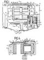
- the partial lining disc brake 2 shown in the drawing has a brake carrier 4 for attachment to a part fixed to the vehicle, such as the steering knuckle.
- the brake carrier 4 consists of a fastening section 6 which extends essentially parallel to a brake disk (not shown) and which has two essentially radially extending legs 8, 10, which are connected via a lower, radially inner connecting section 12 and a radially outer upper ' Connection section 14 are interconnected.
- the legs 8, 10 and the connecting sections 12, 14 form an opening 16, into which part of the leg 18 of the brake frame 20 receiving an actuating device extends.
- the brake piston 24 can be seen here, the end of which protrudes from a brake cylinder bore 26 and, like part of the leg 18 forming the actuating device, extends through the opening 16.
- the upper connecting section 14 of the brake carrier 4 From the radially outer part of the upper connecting section 14 of the brake carrier 4 extend essentially parallel to the brake disc axis running brake carrier arms 28, 30, the outer ends of which are connected by means of a connecting section 32.
- the upper connecting section 14 is axially offset somewhat inwards relative to the lower connecting section 12 on the fastening side, so that inner support surfaces 34, 36 (FIG. 1) for the inner brake lining 38 can be formed in the free area thereby .
- Corresponding support surfaces 40, 42 are provided on the brake carrier arms 28, 30 in their outer area for the outer brake pad 44.
- the outer connecting section 32 which is formed in one piece with the rest of the holder, is offset radially inward somewhat in relation to the inner upper connecting section 14 and lies approximately at the height of the upper limit of the brake piston 24.
- the connecting section 32 has on its radially inner side a support point or a support surface 46 which lies in the region of the axis of symmetry of the brake carrier, which coincides with the sectional plane AA shown in FIG. 1.
- the brake frame 20 has an inner leg 18 and two arms 48, 50 which extend substantially parallel to the brake disc axis or to the brake carrier arms 28, 30 and are connected on the axially outer side by means of a connecting section 52.
- the brake frame 20 is composed of two parts which are screwed together with two connecting screws 54, 55.
- the cutting plane lies approximately at the transition from the leg 18 to the arms 48, 50.
- the leg 18 has two bores 58 (only one can be seen) arranged symmetrically to the axis AA, into which smooth steel guide bolts 60 are pressed.
- the guide bolts 60 extend parallel to the brake disc axis and engage in bores 62 which are provided in the legs 8, 10 of the brake carrier 4 or brake carrier eyes 72 formed thereon.
- the brake carrier eyes 72 extend axially only in the area of the inner brake pad 36.
- the axial projection 70 of the brake carrier eye 72 containing the bore 62 can be formed by a pressed-in sleeve with an integrated protective cap seat. This results in better machining of the step for the elastic sleeve (metaloplast).
- the connecting section 52 of the brake frame 20 has a supporting surface 74 assigned to the supporting point or the supporting surface 46, which is arranged in the region of the center line A-A and thus lies in the upper region of the curved connecting section 52.
- a resilient device 76 is provided, which is designed here as a wire spring.
- the wire spring 76 has a central, U-shaped section 78, which rests on the radially outer upper side of the connecting section 18 of the brake frame 20 and extends at a small angle to the support surface.
- arms 80, 82 extend essentially parallel to the brake disk and at a small angle radially inward, the end parts of which are bent parallel to the brake disk axis and engage in bores provided in the brake support section 14.
- the brake frame 20 is pressed on the inside of the axis formed by the connecting line of the elastic sleeves 64 downwards and on the outside upwards or radially outside, so that the support surface 74 of the connecting portion 52 against the support surface 46 of the Brake carrier 4 is pressed.
- the brake pads 38, 44 are held in the brake carrier 4 by means of pad holding pins 83, 85.
- the pad holding pins 83, 85 extend parallel to the brake disc axis and are guided through elongated openings in the back plates of the brake pads 38, 44.
- Such an opening 84 is shown in FIG. 1.
- Bores in the connecting sections 14, 32 of the brake carrier serve to fasten the lining retaining pins 83, 85.
- Such a bore 86 can also be seen in FIG. 1.
- a cross spring 88 is provided to brace the brake pads 38, 44 against the pad retaining pins 83, 85.
- the cross spring 88 rests with its corresponding legs on the back plates of the brake pads, while legs running transversely thereto engage under the pad holding pins 83, 85.
Landscapes
- Engineering & Computer Science (AREA)
- General Engineering & Computer Science (AREA)
- Mechanical Engineering (AREA)
- Braking Arrangements (AREA)
Abstract
Claims (9)
Applications Claiming Priority (2)
| Application Number | Priority Date | Filing Date | Title |
|---|---|---|---|
| DE3542388 | 1985-11-30 | ||
| DE19853542388 DE3542388A1 (de) | 1985-11-30 | 1985-11-30 | Teilbelag-scheibenbremse, insbesondere fuer kraftfahrzeuge |
Publications (2)
| Publication Number | Publication Date |
|---|---|
| EP0248024A1 EP0248024A1 (fr) | 1987-12-09 |
| EP0248024B1 true EP0248024B1 (fr) | 1989-09-20 |
Family
ID=6287277
Family Applications (1)
| Application Number | Title | Priority Date | Filing Date |
|---|---|---|---|
| EP86905288A Expired EP0248024B1 (fr) | 1985-11-30 | 1986-09-13 | Frein a disque a garniture partielle pour vehicules a moteur |
Country Status (6)
| Country | Link |
|---|---|
| US (1) | US5158159A (fr) |
| EP (1) | EP0248024B1 (fr) |
| JP (1) | JPS63501812A (fr) |
| BR (1) | BR8606910A (fr) |
| DE (2) | DE3542388A1 (fr) |
| WO (1) | WO1987003349A1 (fr) |
Families Citing this family (11)
| Publication number | Priority date | Publication date | Assignee | Title |
|---|---|---|---|---|
| DE3636379C2 (de) * | 1986-10-25 | 1995-05-11 | Teves Gmbh Alfred | Teilbelag-Schwimmsattelbremse, insbesondere für Kraftfahrzeuge |
| US4887696A (en) * | 1988-11-30 | 1989-12-19 | The B. F. Goodrich Company | Disc brake |
| DE3921346C2 (de) * | 1989-06-29 | 1997-05-22 | Teves Gmbh Alfred | Teilbelag-Scheibenbremse |
| DE9003990U1 (de) * | 1990-04-05 | 1991-08-01 | Lucas Industries P.L.C., Birmingham, West Midlands | Teilbelag-Scheibenbremse für Kraftfahrzeuge |
| DE4015167A1 (de) * | 1990-05-11 | 1991-11-14 | Teves Gmbh Alfred | Gehaeusefeder fuer eine teilbelag-scheibenbremse |
| AU4040497A (en) * | 1996-07-12 | 1998-02-09 | Kelsey-Hayes Company | Caliper for disc brake assembly |
| IT1296104B1 (it) * | 1997-11-12 | 1999-06-09 | Freni Brembo Spa | Freno a disco particolarmente per autoveicoli |
| US7249658B2 (en) * | 2004-04-22 | 2007-07-31 | Akebono | Wide caliper assembly design |
| TWI512211B (zh) * | 2013-03-20 | 2015-12-11 | Sanyang Industry Co Ltd | 煞車卡鉗結構 |
| DE102017108175A1 (de) | 2017-04-18 | 2018-10-18 | Bpw Bergische Achsen Kg | Scheibenbremse und Niederhalter zur Befestigung von Bremspads |
| US20190271367A1 (en) * | 2018-03-02 | 2019-09-05 | Arvinmeritor Technology, Llc | Brake assembly having a bridge |
Family Cites Families (27)
| Publication number | Priority date | Publication date | Assignee | Title |
|---|---|---|---|---|
| GB1128324A (en) * | 1964-11-04 | 1968-09-25 | Dunlop Co Ltd | Disc brakes |
| DE6904312U (de) * | 1969-02-05 | 1971-11-04 | Teves Gmbh Alfred | Teilbelagscheibenbremse. |
| DE2061673C3 (de) * | 1969-12-18 | 1979-02-22 | General Motors Corp., Detroit, Mich. (V.St.A.) | Teilbelagscheibenbremse |
| JPS4822065B1 (fr) * | 1970-12-07 | 1973-07-03 | ||
| BE790377A (fr) * | 1971-10-20 | 1973-02-15 | Nissan Motor | Frein a disque |
| JPS5348949Y2 (fr) * | 1972-09-12 | 1978-11-22 | ||
| DE2258116C2 (de) * | 1972-11-28 | 1979-12-13 | Audi Nsu Auto Union Ag, 7107 Neckarsulm | Schwimmrahmen-Teilbelagscheibenbremse |
| DE2340316C3 (de) * | 1973-08-09 | 1984-09-20 | Alfred Teves Gmbh, 6000 Frankfurt | Führung für den Sattel bzw. Rahmen einer Schwimmsattel- bzw. Schwimmrahmenteilbelagscheibenbremse, insbesondere für Kraftfahrzeuge |
| DE2454279A1 (de) * | 1973-11-16 | 1975-05-22 | Ferodo Sa | Scheibenbremse |
| JPS51121665A (en) * | 1975-04-17 | 1976-10-25 | Tokico Ltd | Disk brake |
| FR2345622A1 (fr) * | 1976-03-25 | 1977-10-21 | Ferodo Sa | Frein a disque notamment pour vehicule automobile |
| US4109766A (en) * | 1976-07-06 | 1978-08-29 | Akebono Brake Industry Co., Ltd. | Disc brake |
| JPS5448272U (fr) * | 1977-09-09 | 1979-04-04 | ||
| DE2804808C3 (de) * | 1978-02-04 | 1988-09-29 | Alfred Teves Gmbh, 6000 Frankfurt | Bremsbackenhalterung für eine Teilbelagscheibenbremse, insbesondere für Kraftfahrzeuge |
| JPS54109575A (en) * | 1978-02-16 | 1979-08-28 | Nissan Motor Co Ltd | Disc brake |
| DE2904118A1 (de) * | 1979-02-03 | 1980-09-04 | Teves Gmbh Alfred | Teilbelagscheibenbremse, insbesondere fuer kraftfahrzeuge |
| JPS6029017B2 (ja) * | 1979-03-06 | 1985-07-08 | ワタナベエンジニアリング株式会社 | 車輌用デイスクブレ−キ装置 |
| US4391355A (en) * | 1979-12-03 | 1983-07-05 | Kelsey-Hayes Company | Sliding caliper disc brake |
| FR2470899A1 (fr) * | 1979-12-05 | 1981-06-12 | Dba | Frein a disque |
| FR2478761A1 (fr) * | 1980-03-18 | 1981-09-25 | Dba | Frein a disque |
| FR2500096B1 (fr) * | 1981-02-19 | 1986-02-28 | Dba | Ressort pour frein a disque |
| EP0076202A1 (fr) * | 1981-09-25 | 1983-04-06 | Bendiberica S.A. | Frein à disque à étrier supporté à déplacement axial sur un support fixe |
| DE3243851A1 (de) * | 1982-11-26 | 1984-05-30 | Alfred Teves Gmbh, 6000 Frankfurt | Dichtungsanordnung fuer den fuehrungsbolzen einer schwimmsattel-teilbelagscheibenbremse |
| FR2538487B1 (fr) * | 1982-12-23 | 1985-06-21 | Dba | Frein a disque |
| US4480724A (en) * | 1983-02-22 | 1984-11-06 | General Motors Corporation | Disc brake caliper mounting suspension |
| DE8323802U1 (de) * | 1983-08-18 | 1983-12-01 | Lucas Industries P.L.C., Birmingham, West Midlands | Teilbelag-scheibenbremse mit schwimmsattel |
| FR2563594B1 (fr) * | 1984-04-26 | 1986-07-18 | Dba | Frein a disque a etrier coulissant |
-
1985
- 1985-11-30 DE DE19853542388 patent/DE3542388A1/de not_active Withdrawn
-
1986
- 1986-09-13 US US07/279,595 patent/US5158159A/en not_active Expired - Fee Related
- 1986-09-13 DE DE8686905288T patent/DE3665756D1/de not_active Expired
- 1986-09-13 WO PCT/EP1986/000528 patent/WO1987003349A1/fr not_active Ceased
- 1986-09-13 JP JP61504894A patent/JPS63501812A/ja active Pending
- 1986-09-13 EP EP86905288A patent/EP0248024B1/fr not_active Expired
- 1986-09-13 BR BR8606910A patent/BR8606910A/pt not_active IP Right Cessation
Also Published As
| Publication number | Publication date |
|---|---|
| WO1987003349A1 (fr) | 1987-06-04 |
| JPS63501812A (ja) | 1988-07-21 |
| DE3665756D1 (en) | 1989-10-26 |
| BR8606910A (pt) | 1987-11-03 |
| EP0248024A1 (fr) | 1987-12-09 |
| US5158159A (en) | 1992-10-27 |
| DE3542388A1 (de) | 1987-06-04 |
Similar Documents
| Publication | Publication Date | Title |
|---|---|---|
| EP0695401B1 (fr) | Systeme de fusee d'essieu pour automobiles | |
| EP0341392B1 (fr) | Frein à disque à garniture partielle | |
| DE2816559C2 (de) | Führung für eine Teilbelag-Scheibenbremse, insbesondere für Kraftfahrzeuge | |
| EP0341610A1 (fr) | Frein à disque à garniture partielle | |
| DE3340442C2 (de) | Fahrwerks-Baugruppe für die Anbringung von Radachsen und Bremsen bei Kraftfahrzeugen | |
| EP0248024B1 (fr) | Frein a disque a garniture partielle pour vehicules a moteur | |
| DE2650767A1 (de) | Hydraulisch betaetigte scheibenbremse fuer fahrzeuge | |
| DE4324988A1 (de) | Teilbelag-Scheibenbremse mit einem mehrteiligen Festsattel aus unterschiedlichen Werkstoffen | |
| DE2931071C2 (de) | Kombinierte Niederhalte-Spreizfeder | |
| EP0242722B1 (fr) | Frein à disque, spécialement pour véhicules automobiles | |
| EP0350867B1 (fr) | Frein à disque à garnitures partielles | |
| DE2557302C2 (de) | Teilbelag-Scheibenbremse für Kraftfahrzeuge | |
| EP0826113B1 (fr) | Frein a disque a garniture partielle | |
| DE2745327C2 (fr) | ||
| DE3032513A1 (de) | Schwimmsattel-teilbelagscheibenbremse, insbesondere fuer kraftfahrzeuge | |
| DE3509277C2 (fr) | ||
| DE3445488A1 (de) | Ratterschutz-federanordnung an einem bremsklotz einer teilbelagscheibenbremse | |
| DE4402960C2 (de) | Scheibenbremse | |
| DE19650425B4 (de) | Bremsträger für eine Teilbelagscheibenbremse | |
| EP0150052A2 (fr) | Frein à disque à garniture partielle pour véhicules | |
| DE68908407T2 (de) | Sattelträgerkeil. | |
| EP0119466A1 (fr) | Frein à disque à garniture partielle pour véhicules | |
| DE2938926C2 (de) | Gleitführung für einen schwimmend angebrachten Sattel einer Scheibenbremse, insbesondere für Kraftfahrzeuge | |
| DE3526937A1 (de) | Teilbelagscheibenbremse, insbesondere fuer kraftfahrzeuge | |
| DE4208132A1 (de) | Bremssattel-anordnung |
Legal Events
| Date | Code | Title | Description |
|---|---|---|---|
| PUAI | Public reference made under article 153(3) epc to a published international application that has entered the european phase |
Free format text: ORIGINAL CODE: 0009012 |
|
| 17P | Request for examination filed |
Effective date: 19860913 |
|
| AK | Designated contracting states |
Kind code of ref document: A1 Designated state(s): DE FR GB IT |
|
| 17Q | First examination report despatched |
Effective date: 19880704 |
|
| ITF | It: translation for a ep patent filed | ||
| GRAA | (expected) grant |
Free format text: ORIGINAL CODE: 0009210 |
|
| AK | Designated contracting states |
Kind code of ref document: B1 Designated state(s): DE FR GB IT |
|
| REF | Corresponds to: |
Ref document number: 3665756 Country of ref document: DE Date of ref document: 19891026 |
|
| ET | Fr: translation filed | ||
| GBT | Gb: translation of ep patent filed (gb section 77(6)(a)/1977) | ||
| PLBI | Opposition filed |
Free format text: ORIGINAL CODE: 0009260 |
|
| PLAB | Opposition data, opponent's data or that of the opponent's representative modified |
Free format text: ORIGINAL CODE: 0009299OPPO |
|
| 26 | Opposition filed |
Opponent name: BENDIX EUROPE SERVICES TECHNIQUES Effective date: 19900618 |
|
| R26 | Opposition filed (corrected) |
Opponent name: BENDIX EUROPE SERVICES TECHNIQUES Effective date: 19900619 |
|
| PGFP | Annual fee paid to national office [announced via postgrant information from national office to epo] |
Ref country code: GB Payment date: 19910815 Year of fee payment: 6 |
|
| PGFP | Annual fee paid to national office [announced via postgrant information from national office to epo] |
Ref country code: FR Payment date: 19910927 Year of fee payment: 6 |
|
| ITTA | It: last paid annual fee | ||
| PGFP | Annual fee paid to national office [announced via postgrant information from national office to epo] |
Ref country code: DE Payment date: 19911118 Year of fee payment: 6 |
|
| RDAG | Patent revoked |
Free format text: ORIGINAL CODE: 0009271 |
|
| 27W | Patent revoked |
Effective date: 19820419 |
|
| GBPR | Gb: patent revoked under art. 102 of the ep convention designating the uk as contracting state | ||
| RDAC | Information related to revocation of patent modified |
Free format text: ORIGINAL CODE: 0009299REVO |
|
| STAA | Information on the status of an ep patent application or granted ep patent |
Free format text: STATUS: PATENT REVOKED |
|
| R27W | Patent revoked (corrected) |
Effective date: 19920419 |