EP0246857A2 - Festspannvorrichtung - Google Patents
Festspannvorrichtung Download PDFInfo
- Publication number
- EP0246857A2 EP0246857A2 EP87304418A EP87304418A EP0246857A2 EP 0246857 A2 EP0246857 A2 EP 0246857A2 EP 87304418 A EP87304418 A EP 87304418A EP 87304418 A EP87304418 A EP 87304418A EP 0246857 A2 EP0246857 A2 EP 0246857A2
- Authority
- EP
- European Patent Office
- Prior art keywords
- clamping
- clamping device
- flange
- support beam
- grid
- Prior art date
- Legal status (The legal status is an assumption and is not a legal conclusion. Google has not performed a legal analysis and makes no representation as to the accuracy of the status listed.)
- Withdrawn
Links
Images


Classifications
-
- F—MECHANICAL ENGINEERING; LIGHTING; HEATING; WEAPONS; BLASTING
- F16—ENGINEERING ELEMENTS AND UNITS; GENERAL MEASURES FOR PRODUCING AND MAINTAINING EFFECTIVE FUNCTIONING OF MACHINES OR INSTALLATIONS; THERMAL INSULATION IN GENERAL
- F16B—DEVICES FOR FASTENING OR SECURING CONSTRUCTIONAL ELEMENTS OR MACHINE PARTS TOGETHER, e.g. NAILS, BOLTS, CIRCLIPS, CLAMPS, CLIPS OR WEDGES; JOINTS OR JOINTING
- F16B5/00—Joining sheets or plates, e.g. panels, to one another or to strips or bars parallel to them
- F16B5/06—Joining sheets or plates, e.g. panels, to one another or to strips or bars parallel to them by means of clamps or clips
- F16B5/0607—Joining sheets or plates, e.g. panels, to one another or to strips or bars parallel to them by means of clamps or clips joining sheets or plates to each other
- F16B5/0621—Joining sheets or plates, e.g. panels, to one another or to strips or bars parallel to them by means of clamps or clips joining sheets or plates to each other in parallel relationship
- F16B5/0642—Joining sheets or plates, e.g. panels, to one another or to strips or bars parallel to them by means of clamps or clips joining sheets or plates to each other in parallel relationship the plates being arranged one on top of the other and in full close contact with each other
-
- E—FIXED CONSTRUCTIONS
- E04—BUILDING
- E04B—GENERAL BUILDING CONSTRUCTIONS; WALLS, e.g. PARTITIONS; ROOFS; FLOORS; CEILINGS; INSULATION OR OTHER PROTECTION OF BUILDINGS
- E04B5/00—Floors; Floor construction with regard to insulation; Connections specially adapted therefor
- E04B5/02—Load-carrying floor structures formed substantially of prefabricated units
- E04B5/10—Load-carrying floor structures formed substantially of prefabricated units with metal beams or girders, e.g. with steel lattice girders
-
- E—FIXED CONSTRUCTIONS
- E04—BUILDING
- E04F—FINISHING WORK ON BUILDINGS, e.g. STAIRS, FLOORS
- E04F15/00—Flooring
- E04F15/02—Flooring or floor layers composed of a number of similar elements
- E04F15/06—Flooring or floor layers composed of a number of similar elements of metal, whether or not in combination with other material
-
- F—MECHANICAL ENGINEERING; LIGHTING; HEATING; WEAPONS; BLASTING
- F16—ENGINEERING ELEMENTS AND UNITS; GENERAL MEASURES FOR PRODUCING AND MAINTAINING EFFECTIVE FUNCTIONING OF MACHINES OR INSTALLATIONS; THERMAL INSULATION IN GENERAL
- F16B—DEVICES FOR FASTENING OR SECURING CONSTRUCTIONAL ELEMENTS OR MACHINE PARTS TOGETHER, e.g. NAILS, BOLTS, CIRCLIPS, CLAMPS, CLIPS OR WEDGES; JOINTS OR JOINTING
- F16B2/00—Friction-grip releasable fastenings
- F16B2/02—Clamps, i.e. with gripping action effected by positive means other than the inherent resistance to deformation of the material of the fastening
- F16B2/06—Clamps, i.e. with gripping action effected by positive means other than the inherent resistance to deformation of the material of the fastening external, i.e. with contracting action
- F16B2/065—Clamps, i.e. with gripping action effected by positive means other than the inherent resistance to deformation of the material of the fastening external, i.e. with contracting action using screw-thread elements
-
- Y—GENERAL TAGGING OF NEW TECHNOLOGICAL DEVELOPMENTS; GENERAL TAGGING OF CROSS-SECTIONAL TECHNOLOGIES SPANNING OVER SEVERAL SECTIONS OF THE IPC; TECHNICAL SUBJECTS COVERED BY FORMER USPC CROSS-REFERENCE ART COLLECTIONS [XRACs] AND DIGESTS
- Y10—TECHNICAL SUBJECTS COVERED BY FORMER USPC
- Y10T—TECHNICAL SUBJECTS COVERED BY FORMER US CLASSIFICATION
- Y10T24/00—Buckles, buttons, clasps, etc.
- Y10T24/44—Clasp, clip, support-clamp, or required component thereof
- Y10T24/44265—Gripping member face integral with or rigidly affixed to screw-driving portion
-
- Y—GENERAL TAGGING OF NEW TECHNOLOGICAL DEVELOPMENTS; GENERAL TAGGING OF CROSS-SECTIONAL TECHNOLOGIES SPANNING OVER SEVERAL SECTIONS OF THE IPC; TECHNICAL SUBJECTS COVERED BY FORMER USPC CROSS-REFERENCE ART COLLECTIONS [XRACs] AND DIGESTS
- Y10—TECHNICAL SUBJECTS COVERED BY FORMER USPC
- Y10T—TECHNICAL SUBJECTS COVERED BY FORMER US CLASSIFICATION
- Y10T403/00—Joints and connections
- Y10T403/71—Rod side to plate or side
- Y10T403/7117—Flanged or grooved rod
Definitions
- This invention relates to a clamping device for holding-down a grid-like support member onto a support beam.
- a "grid-like support member” is intended to refer to a support member having at least two generally elongate and longitudinally extending elements which are laterally spaced apart so as to define one or more spaces therebetween, and which are interconnected so as to form a substantially rigid structure.
- the invention has been developed primarily in relation to a clamping device which can be used to hold-down metal grids (or gratings) on support beams, such grids being of the type which can be used as decking, and particularly for marine use e.g. on oil and gas drilling platforms.
- Grids of this type are useful as decking in a marine environment, in that they can provide a sufficiently strong support surface, and yet can readily permit any water which falls on the decking to drain away by gravity through the spaces which are defined between the generally elongate elements or "bars" of the grid.
- clamping device It is well known to use various types of clamping device in order to secure or hold-down grids onto structural beams of a supporting structure.
- the lateral gaps between adjacent bars of grids are often relatively narrow, so that it can be a difficult task, with existing construction of clamping device or "fastener", to install and to tighten the device.
- the lower part of the device has to be passed downwardly through the space, and then has to be manipulated so as to make initial engagement with a part of an underlying support beam. Thereafter, the device has to be tightened, and in such a way that the lower part does not become disengaged from the underlying support beam.
- fastener It is a common experience, with many existing types of fastener, that an initial "hold" of a lower engaging part becomes disengaged when initial tightening of the fastener takes place.
- a clamping device for holding-down a grid-like support member on an underlying flanged support beam, the device being taken in use from the side of the member which is remote from the beam and partly through a space defined through two generally parallel elongate elements of the member, and being manipulatable so as to bring the device into gripping engagement with a flange of the support beam, and the device comprising: a saddle portion which is shaped so as to be capable of being non-rotatably seated on said elements at said one side of the member, a clamping portion which is engageable with one side of the flange of the support beam which is remote from the grid-like member, and a threaded fastener which interconnects the saddle portion and the clamping portion and which is operable relatively to draw the portions towards each other in order to clamp the grid-like member to the support beam when the saddle portion is seated on the elements and when the clamping portion is in engagement with the flange of the support beam; in which the clamping portion has a first part
- a clamping device is particularly suitable for use in holding-down a grid-like decking or grating on flanged support beams, such as I-beams, in which case a number of the clamping devices will be used, each being taken partly through a respective space in the decking which is sufficiently close to an underlying top flange of a support beam so that gripping engagement can take place with the underside of the flange via the first part of the clamping portion.
- step" of the second part which makes seating-engagement with the underside of said element of the grid will depend primarily upon the thickness of the flange. In a preferred embodiment, more than two steps will be provided, so that the clamping device can readily cooperate with a range of flange thicknesses.
- the clamping device is automatically able to compensate for different flange thicknesses, in that it will continue to be rotatable by the fastener (when the device is initially installed in position on the grid and extends downwardly into a respective space) until such time as one of the steps comes snugly into engagement with the underside of said one of the elements.
- the clamping portion is elongate and of dimensions generally corresponding with but smaller than the dimensions of the space between the elements, to enable the clamping portion to be lowered into position, and then rotated into firm engagement with the flange of the underlying support beam.
- each step is shaped so that the "tread" portion thereof slopes gently downwardly to meet the lower end of the adjacent "riser", whereby stable seating of the element can be achieved.
- the further tightening of the clamping device tends to press the respective riser against a side face of the element, and the corresponding step is drawn upwardly into firm engagement with the underside of the element.
- the first part has a curved engaging nose by which it engages the underside of the flange, and this enables the clamping device to rock to a limited extent about the nose during the initial stages of engagement of the clamping portion with the underside of the flange (via the first part) and with the underside of the element (via the second part), until the appropriate step of the second part comes fully into seating engagement with the element.
- the saddle portion is, as indicated above, capable of non-rotative seating engagement with the elements and, usually, this will be the upper edges of the elements.
- the elongate elements of a grid-like decking are formed by flat strips or bars, and preferably the saddle portion includes an inverted U or channel which is able to slide downwardly onto and to embrace one of the bars, so as to resist any tendency for the saddle portion to rotate as the fastener is tightened.
- the channel engages with the upper region of the same element (said one element) which has its lower region engaged by the second part of the clamping portion.
- the saddle portion may include a further inverted channel, into which can fit the upper region of the other bar.
- this further channel may be larger in width than the thickness of the other bar, so that the clamping device can readily be fitted across any two adjacent bars of a range of constructions of grids having different lateral spacings between adjacent bars.
- a saddle portion takes the general form of an inverted "top hat" section, in which the two inverted channels merge into a larger U-shaped member.
- the U-shaped member fits into the space between the two bars, and preferably also serves to mount the threaded fastener.
- the threaded fastener engages via its thread with the clamping portion, and preferably has a rugged design of head which enables the fastener to be tightly secured by a suitable tool from the upper side of the grid.
- One preferred arrangement of head has a hexagonal socket to receive a heavy duty Allen tool.
- an arrow or other indication may be provided on the saddle portion and also on the clamping portion, and the device should be installed so that both arrows point towards the corresponding support beam, and the device is then moved in that direction until the first part engages the underside of the flange and the fastener comes into abutment with the edge of the part engages the underside of the flange and the fastener comes into abutment with the edge of the flange.
- FIG. 10 a grid-like support member (referred to hereinafter as a "grid") which can be held-down on a flanged support beam, using a clamping device according to the invention.
- the grid is designated generally by reference 10, and includes a set of generally elongate and parallel elements 11 in the form of flat strips or bars.
- the grid 10 may be formed so as to be suitable for use as decking in a marine environment e.g. on a drilling rig platform.
- a supporting structure for the decking is formed by a plurality of horizontal flanged support beans 12a (see Figure 5), a typical flange being designated by reference 12 in Figure 2.
- the flange 12 may form, for example, the top flange of an I-beam.
- the elements 11 are laterally spaced apart from each other in order to define a plurality of spaces 13 therebetween, and the elements 11 are laterally interconnected by spacers 14 so that each pair of adjacent elements 11 form a substantially rigid, though water permeable structure.
- a clamping device is designated generally by reference 15, and can be used to hold-down the grid 10 at any desired location on an underlying flanged support beam.
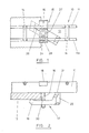
- the clamping device 15 will usually be applied from the side of the grid 10 which is remote from the underlying support beam i.e. from the upper side, and is taken partly through a corresponding space 13, and is thereafter manipulated so as to bring the device into gripping engagement with the underside of flange 12, as shown in Figure 2.
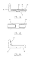
- the clamping device 15 comprises a saddle portion 16, which is shown in more detail in Figures 3a to 3c, and which is shaped so as to be capable of being non-rotatably seated on the upper regions of the elements 11.
- the device 15 also includes a clamping portion 17, which is shown in more detail in Figures 4a to 4e, and which is engageable with the underside of flange 12 i.e. the side of the flange 12 which is remote from the grid 10.
- a threaded fastener 18 which takes the form, in the illustrated embodiment, of an Allen bolt, interconnects the saddle portion 16 and the clamping portion 17, and is operable relatively to draw the portions 16 and 17 towards each other in order to clamp the grid 10 to the support beam when the saddle portion 16 is seated on the elements 11 and when the clamping portion 17 is in engagement with the underside of the flange 12.
- the clamping portion 17 has a first part 19 which is engageable with the underside of the flange 12, and a second part 20 which is generally diametrically opposed to the first part 19 with respect to the axis of the fastener 18, and which has at least two steps 21, each step being shaped so as to be capable of seating-engagement with the underside of one of the elements 11.
- steps 21 which engages the underside of element 11a will depend upon the thickness of the flange 12, and it will be the "riser” 21a of the step which engages the side face of the element 11a, and thereafter resists any further attempt to rotate the clamping portion 17 by the fastener 18.
- the corresponding "tread" portion 21b of the step will fit snugly against the surface of the lower edge of element 11a, and further tightening of the fastener 18 will then cause clamping together of the grid 10 with the underlying support beam.
- the clamping device 15 can readily cooperate with a range of flange thicknesses.
- the clamping device is able to compensate automatically for different flange thicknesses, in that it will continue to be rotatable by the fastener 18 (when the device is initially installed in position on the grid and extends downwardly into the space 13) until such time as an appropriate one of the steps 21 comes snugly into engagement with the underside of the element 11a.
- the tread portion 21b of each step 21 may slope gently downward to meet the lower end of the riser 21a, in order to provide stable seating of the element 11a thereon.
- the first part 19 has a curved engaging nose 22 by which it engages the underside of the flange 12, and this enables the clamping device 15 to rock to a limited extent about the nose 22 during the initial stages of engagement of the clamping portion 17 with the underside of the flange 12, via the first part 19, and with the underside of the element 11a via the second part 20.
- the appropriate step 21 of the second part 20 comes fully into seating engagement with the element 11a.
- the lower end of the fastener 18 has threaded engagement with the clamping portion 17 by being received in a tapped hole 23 formed through a middle region of the clamping portion 17.
- the construction of the saddle portion 16 is shown in more detail in Figures 3a to 3c and it is, as indicated above, capable of non-rotative seating engagement with the elements 11.
- the saddle portion 16 includes a first inverted U or channel 24 which is able to slide downwardly onto and to embrace the upper region of the element 11a, so as to resist any tendency for the saddle portion 16 to rotate as the fastener 18 is tightened. It will be noted from Figure 1 that the channel 24 engages with the upper region of the same element (11a) which has its lower region engaged by one of the steps 21 of the second part 20 of the clamping portion 17.
- the saddle portion 16 includes a further inverted channel 25, and this fits readily onto the upper region of the other one of the bars 11, in that it is larger in width than the thickness of the other bar, so that the clamping device 15 can readily be fitted across any two adjacent bars of a range of constructions of grids having different lateral spacings between adjacent bars.
- the saddle portion 16 takes the general form of an inverted "top hat” section, in which the two inverted channels 24 and 25 merge into a larger U-shaped member 26.
- the member 26 fits into the space 13 defined between the two elements 11, and has a hole in its base in which the fastener 18 is rotatably mounted.
- the fastener 18 has a head 27 with a hexagonal socket, to permit the fastener to be rotated by means of a heavy duty Allen key.
- an arrow 28 or other indication is provided on the saddle portion 16, and an arrow 29 is provided on the first part of the clamping portion 17. This indicates how the device should be installed, in that both arrows 28 and 29 should point towards the corresponding support beam to which the grid is to be attached, and the device 15 is then moved in that direction until the first part 19 engages the underside of the flange 12 and the fastener 18 comes into abutment with the edge 30 of the flange 12.
- Figure 5 illustrates schematically a deck mounted on underlying support beams using clamping devices according to the invention. Parts corresponding with those already described are designated by the same reference numerals, and will not be described in detail again.
- clamping device for holding-down a grid on a support beam, particularly for use as decking, in which the initial installation, and the subsequent tightening of the clamping device can readily be carried out from one side (the upper side) without undue manipulation, and without the installer having to attempt to complete the installation, and the tightening, by inserting his hand or fingers through the space between two bars of the grid in order to hold and/or to manipulate the lower part (the clamping portion) of the clamping device.
- FIGs 1 to 5 there is shown an arrangement whereby one or more clamping devices (15) according to the invention may be used to hold-down a grid on a plurality of laterally spaced and parallel support beams, in which longitudinal strips or bars (11) (from which the grid is made) extend perpendicular to the support beams.
- the clamping device could be used as readily in order to hold-down a grid on support beams in an arrangement wherein the strips or bars extend parallel to the beams, in which case the underlying clamping portion (17) will be manipulated into a position in which it extends parallel to the saddle portion (16) in order to engage the underside of the flange (12).
Landscapes
- Engineering & Computer Science (AREA)
- Architecture (AREA)
- General Engineering & Computer Science (AREA)
- Mechanical Engineering (AREA)
- Civil Engineering (AREA)
- Structural Engineering (AREA)
- Physics & Mathematics (AREA)
- Electromagnetism (AREA)
- Clamps And Clips (AREA)
Applications Claiming Priority (2)
| Application Number | Priority Date | Filing Date | Title |
|---|---|---|---|
| GB868612280A GB8612280D0 (en) | 1986-05-20 | 1986-05-20 | Clamping device |
| GB8612280 | 1986-05-20 |
Publications (2)
| Publication Number | Publication Date |
|---|---|
| EP0246857A2 true EP0246857A2 (de) | 1987-11-25 |
| EP0246857A3 EP0246857A3 (de) | 1988-02-03 |
Family
ID=10598154
Family Applications (1)
| Application Number | Title | Priority Date | Filing Date |
|---|---|---|---|
| EP87304418A Withdrawn EP0246857A3 (de) | 1986-05-20 | 1987-05-19 | Festspannvorrichtung |
Country Status (3)
| Country | Link |
|---|---|
| US (1) | US4759654A (de) |
| EP (1) | EP0246857A3 (de) |
| GB (2) | GB8612280D0 (de) |
Families Citing this family (16)
| Publication number | Priority date | Publication date | Assignee | Title |
|---|---|---|---|---|
| USD303923S (en) | 1986-12-24 | 1989-10-10 | Lindapter International Limited | Grid clamp for support beam or the like |
| US5306064A (en) * | 1993-05-10 | 1994-04-26 | Nina Padovano | Vehicle freight clamping assembly |
| US5678491A (en) * | 1993-12-13 | 1997-10-21 | Alltrista Corporation | Plastic table structure |
| JP2921437B2 (ja) * | 1995-04-12 | 1999-07-19 | トヨタ自動車株式会社 | 締結構造 |
| DE20116015U1 (de) * | 2001-04-12 | 2002-03-07 | LISEGA GmbH, 27404 Zeven | Klemmvorrichtung zum Klemmen von Trägern |
| DE102004021513B4 (de) * | 2004-04-30 | 2012-05-16 | Airbus Operations Gmbh | Einhängklemmhalter für eine Trägerstruktur |
| DE502005001857D1 (de) * | 2004-04-30 | 2007-12-20 | Airbus Gmbh | Klemmhalter für eine Tragstruktur |
| US20090072098A1 (en) * | 2007-09-17 | 2009-03-19 | Inflight Investments Inc. | Support bracket for mounting wires to floor beams of an aircraft |
| US8684320B2 (en) | 2007-09-17 | 2014-04-01 | Inflight Investments Inc. | Support bracket for mounting wires to floor beams of an aircraft |
| US20090293417A1 (en) * | 2008-05-27 | 2009-12-03 | Chunqiao Ren | Grating fastening methods and systems |
| DE202012104226U1 (de) | 2012-11-05 | 2014-01-30 | Hoffmeier Industrieanlagen GmbH & Co. KG | Vorrichtung zur Befestigung von plattenförmigen Elementen an Trägerflanschen |
| US10323788B2 (en) * | 2013-03-14 | 2019-06-18 | William Frank Budleski | Outdoor platform flooring attachment device |
| US20150368895A1 (en) * | 2014-06-19 | 2015-12-24 | Oemetrix, L.L.C. | Mounting bracket for grille |
| JP6347483B2 (ja) * | 2014-08-11 | 2018-06-27 | Jfe機材フォーミング株式会社 | 床板の固定具 |
| JP6862638B2 (ja) * | 2017-05-25 | 2021-04-21 | 双福鋼器株式会社 | 床板連結具 |
| JP7032952B2 (ja) * | 2018-02-23 | 2022-03-09 | 株式会社ニッケンビルド | パネル固定金具及びナット保持部材並びに金属製床パネルと梁材との固定方法及び固定構造 |
Family Cites Families (15)
| Publication number | Priority date | Publication date | Assignee | Title |
|---|---|---|---|---|
| US1474059A (en) * | 1922-07-11 | 1923-11-13 | Carl H Voellmecke | Pipe hanger |
| GB906240A (en) * | 1960-04-04 | 1962-09-19 | English Electric Co Ltd | Improvements in and relating to blind attachment of panels |
| US3003735A (en) * | 1960-06-21 | 1961-10-10 | Erico Prod Inc | Suspension clip |
| US3257134A (en) * | 1962-10-05 | 1966-06-21 | Townsend Company | Spur plate |
| GB1023063A (en) * | 1963-03-04 | 1966-03-16 | Robert Charles Rolland | Improvements in or relating to frame structures for flooring |
| US3463428A (en) * | 1967-06-20 | 1969-08-26 | Robert D Kindorf | Multi-purpose pipe clamp |
| US3524666A (en) * | 1968-08-05 | 1970-08-18 | Pullman Inc | Floor clip |
| US3577316A (en) * | 1969-01-06 | 1971-05-04 | Beloit Corp | Replaceable deflector blade structure for a papermaking machine |
| US3567169A (en) * | 1970-01-12 | 1971-03-02 | Northrop Corp | Disconnect fixture |
| DE2106205A1 (de) * | 1971-02-10 | 1972-08-24 | Steinmueller Gmbh L & C | Klemmelement |
| FR2406113A1 (fr) * | 1977-10-13 | 1979-05-11 | Usiprofil Sarl | Dispositif de fixation |
| US4180343A (en) * | 1978-07-13 | 1979-12-25 | Glenn Finlay | Grating fastener |
| GB2079840B (en) * | 1980-07-16 | 1984-05-10 | Burton Delingpole & Co Ltd | Scaffold clamp |
| US4362422A (en) * | 1980-09-12 | 1982-12-07 | Zinkann Paul J | Grating fastener |
| US4472917A (en) * | 1981-09-24 | 1984-09-25 | Henry Lindsay Limited | Fixing device for mounting a plate on the flange of a beam |
-
1986
- 1986-05-20 GB GB868612280A patent/GB8612280D0/en active Pending
-
1987
- 1987-05-19 EP EP87304418A patent/EP0246857A3/de not_active Withdrawn
- 1987-05-19 GB GB8711772A patent/GB2190951B/en not_active Expired
- 1987-05-20 US US07/052,545 patent/US4759654A/en not_active Expired - Lifetime
Also Published As
| Publication number | Publication date |
|---|---|
| EP0246857A3 (de) | 1988-02-03 |
| GB2190951B (en) | 1989-12-13 |
| GB2190951A (en) | 1987-12-02 |
| GB8711772D0 (en) | 1987-06-24 |
| US4759654A (en) | 1988-07-26 |
| GB8612280D0 (en) | 1986-06-25 |
Similar Documents
| Publication | Publication Date | Title |
|---|---|---|
| US4759654A (en) | Clamping device | |
| US8950157B1 (en) | Solar panel tile roof mounting device installation method | |
| US4757662A (en) | Membrane roofing fastener | |
| US4592186A (en) | Heavy duty anchor for deck boards and the like | |
| EP0048574B1 (de) | Befestigungsvorrichtung für Träger | |
| US20090293417A1 (en) | Grating fastening methods and systems | |
| US4472917A (en) | Fixing device for mounting a plate on the flange of a beam | |
| US5732523A (en) | System for securing composite gratings to structural members | |
| JP3655270B2 (ja) | 屋根補修工法 | |
| JP4091949B2 (ja) | 屋根補修工法 | |
| JP5302662B2 (ja) | デッキ材取付構造 | |
| US4401291A (en) | Concrete wall form with safety attachment | |
| JP2024165565A (ja) | 覆工板および覆工板支持構造 | |
| JP4686020B2 (ja) | 屋根補修工法 | |
| JP3382412B2 (ja) | 覆工板の締結装置 | |
| GB2167488A (en) | Clamp assembly | |
| JP3240493B2 (ja) | ストレーナーの取付具 | |
| US12420905B2 (en) | Modular aircraft floorboard riser systems and methods | |
| EP0923675B1 (de) | Gitterrost-halteklammer | |
| US20250129607A1 (en) | Modular Decking System | |
| EP0116476A2 (de) | Befestigungsmittel | |
| JPS5929060Y2 (ja) | 建物用すべり止め | |
| JP6922659B2 (ja) | 支持具、太陽電池モジュールの取付ユニットおよび太陽電池モジュールの取付方法 | |
| DE19702167A1 (de) | Befestigungssystem für an einem Sparren eines Daches anzuordnende Bedachungsartikel | |
| JP4747080B2 (ja) | グレーチング固定装置 |
Legal Events
| Date | Code | Title | Description |
|---|---|---|---|
| PUAI | Public reference made under article 153(3) epc to a published international application that has entered the european phase |
Free format text: ORIGINAL CODE: 0009012 |
|
| AK | Designated contracting states |
Kind code of ref document: A2 Designated state(s): AT BE CH DE ES FR GB GR IT LI LU NL SE |
|
| PUAL | Search report despatched |
Free format text: ORIGINAL CODE: 0009013 |
|
| RHK1 | Main classification (correction) |
Ipc: F16B 2/18 |
|
| AK | Designated contracting states |
Kind code of ref document: A3 Designated state(s): AT BE CH DE ES FR GB GR IT LI LU NL SE |
|
| 17P | Request for examination filed |
Effective date: 19880129 |
|
| 17Q | First examination report despatched |
Effective date: 19880906 |
|
| STAA | Information on the status of an ep patent application or granted ep patent |
Free format text: STATUS: THE APPLICATION IS DEEMED TO BE WITHDRAWN |
|
| 18D | Application deemed to be withdrawn |
Effective date: 19890621 |
|
| RIN1 | Information on inventor provided before grant (corrected) |
Inventor name: GILL, NEIL FRANK Inventor name: MARTIN, GRAHAM LESTER |