EP0923675B1 - Gitterrost-halteklammer - Google Patents
Gitterrost-halteklammer Download PDFInfo
- Publication number
- EP0923675B1 EP0923675B1 EP97940228A EP97940228A EP0923675B1 EP 0923675 B1 EP0923675 B1 EP 0923675B1 EP 97940228 A EP97940228 A EP 97940228A EP 97940228 A EP97940228 A EP 97940228A EP 0923675 B1 EP0923675 B1 EP 0923675B1
- Authority
- EP
- European Patent Office
- Prior art keywords
- limb
- clip
- grating
- flange
- cells
- Prior art date
- Legal status (The legal status is an assumption and is not a legal conclusion. Google has not performed a legal analysis and makes no representation as to the accuracy of the status listed.)
- Expired - Lifetime
Links
- 239000002184 metal Substances 0.000 claims abstract description 6
- 238000000034 method Methods 0.000 claims description 4
- 230000015572 biosynthetic process Effects 0.000 claims description 3
- 238000005755 formation reaction Methods 0.000 claims description 3
- 210000003414 extremity Anatomy 0.000 description 34
- 210000003141 lower extremity Anatomy 0.000 description 7
- 210000001364 upper extremity Anatomy 0.000 description 4
- 238000007373 indentation Methods 0.000 description 3
- XLYOFNOQVPJJNP-UHFFFAOYSA-N water Substances O XLYOFNOQVPJJNP-UHFFFAOYSA-N 0.000 description 2
- 230000002411 adverse Effects 0.000 description 1
- 238000010276 construction Methods 0.000 description 1
- 238000009408 flooring Methods 0.000 description 1
- 238000003780 insertion Methods 0.000 description 1
- 230000037431 insertion Effects 0.000 description 1
- 238000009434 installation Methods 0.000 description 1
- 239000003562 lightweight material Substances 0.000 description 1
- 238000012986 modification Methods 0.000 description 1
- 230000004048 modification Effects 0.000 description 1
Images

Classifications
-
- F—MECHANICAL ENGINEERING; LIGHTING; HEATING; WEAPONS; BLASTING
- F16—ENGINEERING ELEMENTS AND UNITS; GENERAL MEASURES FOR PRODUCING AND MAINTAINING EFFECTIVE FUNCTIONING OF MACHINES OR INSTALLATIONS; THERMAL INSULATION IN GENERAL
- F16B—DEVICES FOR FASTENING OR SECURING CONSTRUCTIONAL ELEMENTS OR MACHINE PARTS TOGETHER, e.g. NAILS, BOLTS, CIRCLIPS, CLAMPS, CLIPS OR WEDGES; JOINTS OR JOINTING
- F16B2/00—Friction-grip releasable fastenings
- F16B2/20—Clips, i.e. with gripping action effected solely by the inherent resistance to deformation of the material of the fastening
- F16B2/22—Clips, i.e. with gripping action effected solely by the inherent resistance to deformation of the material of the fastening of resilient material, e.g. rubbery material
- F16B2/24—Clips, i.e. with gripping action effected solely by the inherent resistance to deformation of the material of the fastening of resilient material, e.g. rubbery material of metal
- F16B2/241—Clips, i.e. with gripping action effected solely by the inherent resistance to deformation of the material of the fastening of resilient material, e.g. rubbery material of metal of sheet metal
- F16B2/245—Clips, i.e. with gripping action effected solely by the inherent resistance to deformation of the material of the fastening of resilient material, e.g. rubbery material of metal of sheet metal external, i.e. with contracting action
-
- E—FIXED CONSTRUCTIONS
- E04—BUILDING
- E04C—STRUCTURAL ELEMENTS; BUILDING MATERIALS
- E04C2/00—Building elements of relatively thin form for the construction of parts of buildings, e.g. sheet materials, slabs, or panels
- E04C2/30—Building elements of relatively thin form for the construction of parts of buildings, e.g. sheet materials, slabs, or panels characterised by the shape or structure
- E04C2/42—Gratings; Grid-like panels
- E04C2/428—Separate connecting means, e.g. connecting gratings to underlying structure
Definitions
- This invention relates to a hold-down clip for use with a grating, in order to secure the grating to an underlying structure of support beams.
- Gratings are used widely in industry as support surfaces e.g. on walkways alongside plant and machinery, fire escapes, decks on oil rigs, helicopter platforms and the like, and have the advantage of being manufactured in standard lengths and widths, and in being relatively easily assembled on site with support beams using a number of different designs of releasable fasteners.
- Gratings are usually formed with a number of identical cells of rectangular, and more usually square cross section and comprise parallel longitudinal metal strips and transverse metal strips which usually extend perpendicular to the longitudinal strips.
- the metal strips are usually welded together and the longitudinal strips stand edge-on to the supporting surfaces of the support beams.
- the supporting surfaces are usually generally horizontal, and the strips are therefore contained in generally vertical planes.
- the transverse strips are of smaller width than the longitudinal strips, and interconnect the upper edges of the longitudinal strips so that together the longitudinal and transverse strips form a reliable common support surface.
- the cells In marine use, the cells allow storm water rapidly to drain through the cells, while leaving a reliable support surface for personnel. The cells also allow rain water to be drained.
- the support surfaces on which the gratings rest are usually formed by the top surfaces of flanged beams e.g. angle, channel or I-beams, and the clips used to hold-down the gratings engage downwardly onto one or more of the cells of the grating, and also engage with the undersides of the flanged beams.
- Existing designs of clip take many forms, one of which includes a saddle type of device which can seat itself into one or more of the cells, a clamping portion to engage the underside of the flange, and a threaded fastener which extends downwardly throught eh saddle and the clamping portion.
- the fastener may make threaded engagement with the clamping portion, or could pass through it so that a fastener nut can be engaged on the projecting threaded end. Tightening of the fastener then clamps the grating to the flange.
- the invention seeks to simplify the assembly operation by providing a one-piece clip configuration and which avoids use of a threaded fastener to complete the operation.
- GB-A-2 135 044 It is known from GB-A-2 135 044 to provide a hold-down clip having a U-shape with limbs having bent portions at the free ends, and which is used in order to connect a louvre to a vertical mullion, and in which the clip grips a flange of the louvre, and engages through an opening in the mullion, in order to mount the louvre on the mullion.
- the U-shaped formation of the clip is formed by a pair of parallel smooth limbs, and which lie alongside respective parts of the flange of the louvre, and the back face of the mullion, after the clip has been rotated to the fully assembled position.
- the clip is made of resilient and relatively light weight material, and serves mainly to locate the flange of the louvre adjacent to the mullion.
- the clip is necessary to provide saw tooth shaped louvre supports, which are secured to the mullion, and which form the major vertical support for the louvre.
- the present invention provides a one-piece clip configuration which is more robust in construction than the known U-shaped clip formations, and which has characterising features which facilitate part rotational assembly of the clip with a fulcrum type of inter-engagement with the cells of the grating, thereby allowing a downward pressing or impact force to be utilised to complete the assembly.
- a hold-down clip for use with a metal grating formed of longitudinal strips and transverse strips joined together to form a number of cells of generally rectangular cross section, said clip being operable to secure one or more cells of the grating to a flange of an underlying support beam, in which the clip comprises:
- a clip according to the invention therefore only requires manual handling for the initial presentation of the clip to a particular cell, but thereafter (following engagement of the inward projection with the top edge of one of the transverse walls of one of the cells) the clip can be rotated to the fully assembled position by any suitable means which involves application of a downward pressing or impact force.
- This avoids any necessity to carry out manipulation operations below the surface of the grating e.g. to complete the clamping of a threaded fastener as per the known clips, and the assembly can be completed simply by an operative stamping downwardly onto the clip.
- the inward projection may be repeated, or mirrored, along the underside of the upper surface of the clip, so as to provide bi-directional restraint i.e. in which one projection is engageable with a respective strip of the grating so as to resist movement in one direction, whereas the additional projection is engageable with an adjacent strip of the grating so as to resist movement in an opposite direction.
- the second bent portion at the free end of the second limb usually will come into engagement with the side edge of the flange, when the clip is manipulated to an intermediate position, and then slides downwardly over this edge as the final assembly operation takes place, whereby to guide the second limb to move into engagement with the underside of the flange as the clip carries out its rotation to the fully assembled position.
- clips will be located at reasonably uniform intervals along the length of each flange edge e.g. a clip being provided every 20mm, so as to provide reliable securement of the grating to the support beams.
- Dis-assembly will not often be required, but when necessary can be carried out simply using a simple tool, such as a screwdriver, to engage under the firm limb of each clip, and operated to lever the clip upwardly in a pivoting type of movement to take-up the intermediate position, and then the preliminary mounting and location position, whereby the clip can then be manually removed easily when required.
- a simple tool such as a screwdriver
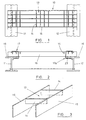
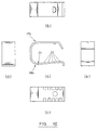
- a grating which is designated generally by the reference 10, and which is intended to be used to form a substantially horizontal support surface e.g. a walkway, and to be assembled on site on underlying parallel support beams, two of which are shown by reference 11 and 12.
- the beams 11 and 12 are flanged beams, and in the illustrated example are I-beams. However, other designs of flanged beams may be used to form the support beams, including angles, and channels.
- the grating 10 is formed with a number of identical cells 13 which are shown being of square cross section, although rectangular cross section cells also may be provided. Each cell 13 is defined between an adjacent pair of transverse connecting strips 14, and a pair of longitudinally extending strips 15.
- the strips 14 and 15 are contained in generally vertical planes, and the longitudinal strips 15 are of greater depth, so that they can be supported edge-on to the supporting surfaces formed by flanges 16 of beams 11 and 12.
- the transverse strips 14 are of smaller width, and interconnect the upper edges of the longitudinal strips 15. In some designs, the upper edges of the transverse strips 14 may be ribbed or castellated to improve grip by the boots or shoes of personnel walking over the grating.
- Figure 3 shows schematically and in perspective illustration a cell 13 formed between opposed pairs of strips 14 and 15.
- hold-down clip according to the invention will now be described, which can be used in order to hold-down the grating 10 on the supporting surfaces of the beams 11 and 12.
- the examples of the invention are clips of one-piece configuration, and which avoid use of a threaded fastener to complete the operation.
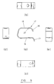
- the clip comprises a generally U-shaped one-piece configuration, as can be seen in a simplified embodiment of clip shown in Figure 9, and designated generally by reference 17.
- the clip 17 has a pair of opposed first and second limbs 18 and 19 respectively, which form facing sides of the generally U-shaped configuration.
- a first bent portion 20 is formed at a free end of the first limb 18, and which is inclined in a direction towards the second limb 19.
- a second bent portion 21 is formed at a free end of the second limb 19, and which is inclined in a direction away from the first limb 18.
- the embodiment of Figure 9 also has a projection 22 which is stamped or otherwise deformed inwardly of the first limb 18, and located near to the first bent portion 20.
- an additional projection 22a may be provided.
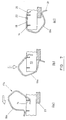
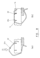
- stages 1 and 2 may be carried in one single location and manipulation operation, as shown in Figure 8.
- Figures 4 to 6 show successive stages in: initial mounting and location; manipulation to the intermediate position; and rotation to the fully assembled position. This is a schematic illustration applicable to the embodiment of clip 17 shown in Figure 9.
- Figures 7a to c show successive stages applicable to use of a modified design of hold-down clip 17a according to the invention, in which the second limb, shown by reference 19a, includes a curved deformation, to give the second limb additional resilience, and thereby to facilitate the initial assembly, and to provide a reliable securement of the clip in the hold-down position.
- the inward projection 22 which assists in the initial guiding of the clip both to the initial mounting and location position, and also to manipulation to the intermediate position. It is engageable with one of the transverse strips or walls 14, and when the downward force is applied, the projection 22 acts as a fulcrum, whereby the downward force applied to the clip is converted into rotary motion so that the clip can be sprung into the fully assembled position.
- the projection 22 may be omitted.
- the additional projection 22a is provided, so that the clip has bi-directional restraint when installed i.e. projection 22 engages one of the strips 14 to resist movement in one direction, and projection 22a engages the adjacent strip 14 to resist movement in the opposite direction.
- the application of downward force to the clip may be carried out by a hammer or mallet, or simply by an operative stamping on the clip, and which can easily be done as he walks along the partly assembled grating.
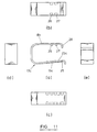
- Figure 10 shows a further modified design of a hold-down clip 17b according to the invention, in which the second limb, shown by reference 19b, includes a number of identations 23 proving a serrated upper surface 24 to lower limb 19b, to enhance the grip performance of the lower limb against the underside of the flange, when fully assembled in the hold-down position.
- the shape geometry of the identations can be any providing enhanced grip, but preferably can vary from having a smooth, semi-circular profile, to a triangular profile having a pointed vertex.
- the hold-down clip is designated generally by reference 17c, and has further design modification to lower limb 19c and upper limb 18c.
- the second or lower limb 19c has indentations 23c, which enhance the grip performance of the lower limb against the underside of the flange, when fully assembled in the hold-down position.
- the generally wavy indentations 23c terminate in a hooked end 25, to give improved gripping engagement with a flange of the steelwork.
- the first or upper limb 18c has a pair of down-turned tabs 26 and 27, spaced from the down-turned free end 28 of the limbs.
- the tabs 26 and 27 are formed by deformation from the side edges of the upper limb 18c, as shown in Figure 11b. These tabs 26 and 27, acting in conjunction with down-turned end 28, provide further possibility of adjustment, during installation and assembly, to suit different designs of grid. This is permitted by variation in the extent of adjustment longitudinally of the upper limb 18c, backwards or forwards, to achieve reliable engagement with the flanges of the adjoining steelwork.
Landscapes
- Engineering & Computer Science (AREA)
- General Engineering & Computer Science (AREA)
- Architecture (AREA)
- Mechanical Engineering (AREA)
- Civil Engineering (AREA)
- Structural Engineering (AREA)
- Clamps And Clips (AREA)
- Superconductors And Manufacturing Methods Therefor (AREA)
- Optical Communication System (AREA)
- Sheet Holders (AREA)
- Cable Accessories (AREA)
- Flanged Joints, Insulating Joints, And Other Joints (AREA)
- Battery Mounting, Suspending (AREA)
- Motor Or Generator Frames (AREA)
- Control Of Throttle Valves Provided In The Intake System Or In The Exhaust System (AREA)
- Bidet-Like Cleaning Device And Other Flush Toilet Accessories (AREA)
- Treating Waste Gases (AREA)
Claims (7)
- Niederhalteklammer für ein Metallgitter (10), das aus Längsstreifen (15) und Querstreifen (14) gebildet ist, die zum Bilden von mehreren Zellen (13) mit einem im wesentlichen rechtwinkligen Querschnitt miteinander verbunden sind, wobei die Klammer mindestens eine Zelle des Gitters (10) an einem Flansch (16) eines darunter liegenden Tragbalkens (11, 12) befestigen kann, wobei die Klammer aufweist:dadurch gekennzeichnet, dassa) eine im wesentlichen U-förmige einteilige Ausgestaltung;b) zwei gegenüberliegende Schenkel, einen ersten Schenkel (18) und einen zweiten Schenkel (19), die gegenüberliegende Seiten der im wesentlichen U-förmigen Ausgestaltung bilden;c) einen ersten Schenkelabschnitt (20) am freien Ende des ersten Schenkels (18), der in Richtung des zweiten Schenkels (19) geneigt ist; undd) einen zweiten Schenkelabschnitt (21) an dem freien Ende des zweiten Schenkels (19), der weg von dem ersten Schenkel (18) geneigt ist;
der erste Schenkel (18) der Klammer einen nach innen gerichteten Vorsprung (22) aufweist, der nahe dem ersten Schenkelabschnitt (20) angeordnet ist, wobei dieser Vorsprung in Eingriff mit der oberen Kante einer der Querstreifen (14) einer der Zellen (13) gelangen kann, um als Drehpunkt beim Anbringen der Klammer für ein Sichern mindestens einer Zelle des Gitters (10) an dem Flansch (16) des darunter liegenden Tragbalkens (11, 12) zu agieren. - Klammer nach Anspruch 1, dadurch gekennzeichnet, dass der zweite Schenkel (19b) mit Haftstrukturen (23) für eine Vergrößerung der Haftleistung des zweiten Schenkels gegen die Unterseite des Flansches (16) des darunter liegenden Tragbalkens (11, 12) gebildet ist.
- Klammer nach einem der Ansprüche 1 oder 2, dadurch gekennzeichnet, dass der erste Schenkel (18) der Klammer einen ersten nach innen gerichteten Vorsprung (22), der mit einem entsprechenden Streifen (14) des Gitters (10) in Eingriff gelangen kann, um einer Bewegung in einer Richtung entgegenzuwirken, und einen zweiten nach innen gerichteten Vorsprung (22a) aufweist, um einer Bewegung in entgegengesetzter Richtung entgegenzuwirken.
- Klammer nach Anspruch 3, dadurch gekennzeichnet, dass sich der erste nach innen gerichtete Vorsprung (22) nach innen in Richtung des zweiten Schenkels (19) und zusätzlich in Richtung des ersten Schenkelabschnitts (20) erstreckt, und dass sich der zweite nach innen gerichtete Vorsprung (22a) nach innen und zusätzlich weg von dem ersten Schenkelabschnitt (20) erstreckt.
- Klammer nach einem der vorhergehenden Ansprüche, dadurch gekennzeichnet, dass der erste Schenkel (18c) ein nach unten gedrehtes freies Ende (28) und zwei Vorsprünge (26 und 27) aufweist, die von dem freien Ende (28) beabstandet sind und sich nach innen in Richtung des zweiten Schenkels (19c) und zusätzlich in Richtung des freien Endes (28) erstrecken, wobei die Vorsprünge (26 und 27) für eine Längseinstellung des ersten Schenkels (18c) beim Anbringen voneinander beabstandet sind.
- Klammer nach einem der vorhergehenden Ansprüche, dadurch gekennzeichnet, dass der zweite Schenkel (19c) ein hakenförmiges Ende (25) für einen Hafteingriff mit dem Flansch (16) des darunter liegenden Tragbalkens (11, 12) aufweist.
- Verfahren für ein Anbringen eines Gitters (10) an Flansche (16) seitlich beabstandeter, unterliegender Parallel-Tragbalken (11, 12) mittels mehreren Niederhalte-klammern (17), wobei:wobei das Verfahren ferner die Schritte umfasst:a) das Gitter (10) aus Längsstreifen (15) und Querstreifen (14) gebildet wird, die zum Bilden von mehreren Zellen (13) mit einem im wesentlichen rechtwinkligen Querschnitt miteinander verbunden werden; und wobeib) jede Klammer (17) mindestens eine Zelle (13) des Gitters (10) an eine Flansch (16) eines darunter liegenden Tragbalkens (11, 12) befestigen kann, wobei die Klammer aufweist: eine im wesentlichen U-förmige einteilige Ausgestaltung; zwei gegenüberliegende Schenkel, einen ersten Schenkel (18) und einen zweiten Schenkel (19), die gegenüberliegende Seiten der im allgemeinen U-förmigen Ausgestaltung bilden; einen ersten Schenkelabschnitt (20) am freien Ende des ersten Schenkels (18), der in Richtung des zweiten Schenkels (19) und weg von dem ersten Schenkel (18) geneigt ist; und einen nach innen gerichteten Vorsprung (22) auf dem ersten Schenkel (18), der nahe dem Schenkelabschnitt (20) angeordnet ist;a) anfängliches Zusammenbauen jeder Klammer (17) mit zwei benachbarten Längsstreifen (14) einer Zelle (13) des Gitters (10) und mit der Zelle (13), die oberhalb und nahe einer Kante 123) des darunter liegenden Flansches (16) eines der Tragbalken (11, 12) angeordnet wird; undb) teilweise Drehen jeder Klammer von der anfänglichen Zusammenbaustellung derart, dass der nach innen gerichtete Vorsprung (22) mit der oberen Kante einer der Längswände einer der Zellen (13) in Eingriff gelangt und dadurch als Drehpunkt agiert, und danach Anlegen eines nach unten gerichteten Druckes oder einer Stoßkraft an die Klammer, wodurch die Klammer eine vollständig zusammengebaute Stellung einnimmt, in der der erste Schenkel (18) die Längsstreifen (14) der Zelle (13) überlagert und der zweite Schenkel (19) teilweise unter dem Flansch (16) liegt.
Applications Claiming Priority (5)
| Application Number | Priority Date | Filing Date | Title |
|---|---|---|---|
| GBGB9618373.6A GB9618373D0 (en) | 1996-09-04 | 1996-09-04 | Grating hold-down clip |
| GB9618373 | 1996-09-04 | ||
| GB9700577 | 1997-01-13 | ||
| GBGB9700577.1A GB9700577D0 (en) | 1996-09-04 | 1997-01-13 | Grating hold-down clip |
| PCT/GB1997/002361 WO1998010195A1 (en) | 1996-09-04 | 1997-09-03 | Grating hold-down clip |
Publications (2)
| Publication Number | Publication Date |
|---|---|
| EP0923675A1 EP0923675A1 (de) | 1999-06-23 |
| EP0923675B1 true EP0923675B1 (de) | 2001-08-16 |
Family
ID=26309965
Family Applications (1)
| Application Number | Title | Priority Date | Filing Date |
|---|---|---|---|
| EP97940228A Expired - Lifetime EP0923675B1 (de) | 1996-09-04 | 1997-09-03 | Gitterrost-halteklammer |
Country Status (6)
| Country | Link |
|---|---|
| EP (1) | EP0923675B1 (de) |
| AT (1) | ATE204363T1 (de) |
| DE (1) | DE69706182T2 (de) |
| GB (1) | GB9700577D0 (de) |
| NO (1) | NO991066L (de) |
| WO (1) | WO1998010195A1 (de) |
Family Cites Families (4)
| Publication number | Priority date | Publication date | Assignee | Title |
|---|---|---|---|---|
| DE2500525A1 (de) * | 1975-01-08 | 1976-07-15 | Stapelmann & Co | Klammer zum verbinden von gitterrosten oder dergleichen mit diese aufnehmenden tragkonstruktionen bzw. untereinander |
| GB2135044B (en) * | 1983-02-08 | 1986-06-11 | John Sidney Jordan | Louvre and mullion system |
| US4605978A (en) * | 1984-11-23 | 1986-08-12 | Mark Zeavin | Clip system for immoveably mounting a magnetic head on a support |
| DE9203133U1 (de) * | 1992-03-10 | 1992-06-25 | Fritz Schäfer GmbH, 57290 Neunkirchen | Befestigungselement |
-
1997
- 1997-01-13 GB GBGB9700577.1A patent/GB9700577D0/en active Pending
- 1997-09-03 EP EP97940228A patent/EP0923675B1/de not_active Expired - Lifetime
- 1997-09-03 AT AT97940228T patent/ATE204363T1/de not_active IP Right Cessation
- 1997-09-03 WO PCT/GB1997/002361 patent/WO1998010195A1/en not_active Ceased
- 1997-09-03 DE DE69706182T patent/DE69706182T2/de not_active Expired - Lifetime
-
1999
- 1999-03-04 NO NO991066A patent/NO991066L/no not_active Application Discontinuation
Also Published As
| Publication number | Publication date |
|---|---|
| EP0923675A1 (de) | 1999-06-23 |
| NO991066D0 (no) | 1999-03-04 |
| NO991066L (no) | 1999-04-23 |
| ATE204363T1 (de) | 2001-09-15 |
| GB9700577D0 (en) | 1997-03-05 |
| WO1998010195A1 (en) | 1998-03-12 |
| DE69706182D1 (de) | 2001-09-20 |
| DE69706182T2 (de) | 2002-05-02 |
Similar Documents
| Publication | Publication Date | Title |
|---|---|---|
| US6708460B1 (en) | Stud wall system and method using a combined bridging and spacing device | |
| US9809976B2 (en) | Beam clip with teeth | |
| CA2015733C (en) | Deck clip system, method and connector connection | |
| EP0196182A2 (de) | Unterstützungsanordnung | |
| WO1998009030A1 (en) | Wall stud connectors | |
| KR102072965B1 (ko) | 공동주택용 석재 고정장치 | |
| USRE40217E1 (en) | System for securing composite gratings to structural members | |
| EP0923675B1 (de) | Gitterrost-halteklammer | |
| US5911664A (en) | Fastening system for securing composite gratings to structural members | |
| JP5124773B2 (ja) | スレート葺屋根の補修構造およびその補修工法 | |
| GB2084628A (en) | Roof edge fascia | |
| AU768502B2 (en) | Stud wall system and method using combined bridging and spacing device | |
| JP4091949B2 (ja) | 屋根補修工法 | |
| US5806121A (en) | Lightweight weldless gratings or grids for bridge decks | |
| US20100212251A1 (en) | Roof securing system | |
| JP4654218B2 (ja) | 折版屋根材の固定金具 | |
| GB2135044A (en) | Louvre and mullion system | |
| JP7158250B2 (ja) | 建築用部材の固定構造 | |
| US5167091A (en) | Clip and method for supporting plants on wooden fences | |
| JP2016130441A (ja) | 波形スレート屋根改修工法 | |
| KR102257347B1 (ko) | 그레이팅 결합용 고정구 | |
| EP0005418B1 (de) | Lastübertragendes Befestigungselement für Gitterroste | |
| AU2003100525A4 (en) | Anchor device | |
| GB2387210A (en) | Decking clip | |
| GB2185275A (en) | Builders straps with fasteners and anchors |
Legal Events
| Date | Code | Title | Description |
|---|---|---|---|
| PUAI | Public reference made under article 153(3) epc to a published international application that has entered the european phase |
Free format text: ORIGINAL CODE: 0009012 |
|
| 17P | Request for examination filed |
Effective date: 19990319 |
|
| AK | Designated contracting states |
Kind code of ref document: A1 Designated state(s): AT BE CH DE DK ES FI FR GB IE IT LI LU NL PT SE |
|
| 17Q | First examination report despatched |
Effective date: 19991011 |
|
| GRAG | Despatch of communication of intention to grant |
Free format text: ORIGINAL CODE: EPIDOS AGRA |
|
| GRAG | Despatch of communication of intention to grant |
Free format text: ORIGINAL CODE: EPIDOS AGRA |
|
| GRAH | Despatch of communication of intention to grant a patent |
Free format text: ORIGINAL CODE: EPIDOS IGRA |
|
| GRAH | Despatch of communication of intention to grant a patent |
Free format text: ORIGINAL CODE: EPIDOS IGRA |
|
| GRAA | (expected) grant |
Free format text: ORIGINAL CODE: 0009210 |
|
| AK | Designated contracting states |
Kind code of ref document: B1 Designated state(s): AT BE CH DE DK ES FI FR GB IE IT LI LU NL PT SE |
|
| PG25 | Lapsed in a contracting state [announced via postgrant information from national office to epo] |
Ref country code: NL Free format text: LAPSE BECAUSE OF FAILURE TO SUBMIT A TRANSLATION OF THE DESCRIPTION OR TO PAY THE FEE WITHIN THE PRESCRIBED TIME-LIMIT Effective date: 20010816 Ref country code: LI Free format text: LAPSE BECAUSE OF FAILURE TO SUBMIT A TRANSLATION OF THE DESCRIPTION OR TO PAY THE FEE WITHIN THE PRESCRIBED TIME-LIMIT Effective date: 20010816 Ref country code: IT Free format text: LAPSE BECAUSE OF FAILURE TO SUBMIT A TRANSLATION OF THE DESCRIPTION OR TO PAY THE FEE WITHIN THE PRESCRIBED TIME-LIMIT;WARNING: LAPSES OF ITALIAN PATENTS WITH EFFECTIVE DATE BEFORE 2007 MAY HAVE OCCURRED AT ANY TIME BEFORE 2007. THE CORRECT EFFECTIVE DATE MAY BE DIFFERENT FROM THE ONE RECORDED. Effective date: 20010816 Ref country code: FI Free format text: LAPSE BECAUSE OF FAILURE TO SUBMIT A TRANSLATION OF THE DESCRIPTION OR TO PAY THE FEE WITHIN THE PRESCRIBED TIME-LIMIT Effective date: 20010816 Ref country code: CH Free format text: LAPSE BECAUSE OF FAILURE TO SUBMIT A TRANSLATION OF THE DESCRIPTION OR TO PAY THE FEE WITHIN THE PRESCRIBED TIME-LIMIT Effective date: 20010816 Ref country code: BE Free format text: LAPSE BECAUSE OF FAILURE TO SUBMIT A TRANSLATION OF THE DESCRIPTION OR TO PAY THE FEE WITHIN THE PRESCRIBED TIME-LIMIT Effective date: 20010816 Ref country code: AT Free format text: LAPSE BECAUSE OF FAILURE TO SUBMIT A TRANSLATION OF THE DESCRIPTION OR TO PAY THE FEE WITHIN THE PRESCRIBED TIME-LIMIT Effective date: 20010816 |
|
| REF | Corresponds to: |
Ref document number: 204363 Country of ref document: AT Date of ref document: 20010915 Kind code of ref document: T |
|
| REG | Reference to a national code |
Ref country code: CH Ref legal event code: EP |
|
| PG25 | Lapsed in a contracting state [announced via postgrant information from national office to epo] |
Ref country code: LU Free format text: LAPSE BECAUSE OF NON-PAYMENT OF DUE FEES Effective date: 20010903 Ref country code: IE Free format text: LAPSE BECAUSE OF NON-PAYMENT OF DUE FEES Effective date: 20010903 |
|
| REF | Corresponds to: |
Ref document number: 69706182 Country of ref document: DE Date of ref document: 20010920 |
|
| REG | Reference to a national code |
Ref country code: IE Ref legal event code: FG4D |
|
| PG25 | Lapsed in a contracting state [announced via postgrant information from national office to epo] |
Ref country code: SE Free format text: LAPSE BECAUSE OF FAILURE TO SUBMIT A TRANSLATION OF THE DESCRIPTION OR TO PAY THE FEE WITHIN THE PRESCRIBED TIME-LIMIT Effective date: 20011116 Ref country code: PT Free format text: LAPSE BECAUSE OF FAILURE TO SUBMIT A TRANSLATION OF THE DESCRIPTION OR TO PAY THE FEE WITHIN THE PRESCRIBED TIME-LIMIT Effective date: 20011116 Ref country code: DK Free format text: LAPSE BECAUSE OF FAILURE TO SUBMIT A TRANSLATION OF THE DESCRIPTION OR TO PAY THE FEE WITHIN THE PRESCRIBED TIME-LIMIT Effective date: 20011116 |
|
| REG | Reference to a national code |
Ref country code: GB Ref legal event code: IF02 |
|
| NLV1 | Nl: lapsed or annulled due to failure to fulfill the requirements of art. 29p and 29m of the patents act | ||
| PG25 | Lapsed in a contracting state [announced via postgrant information from national office to epo] |
Ref country code: ES Free format text: LAPSE BECAUSE OF FAILURE TO SUBMIT A TRANSLATION OF THE DESCRIPTION OR TO PAY THE FEE WITHIN THE PRESCRIBED TIME-LIMIT Effective date: 20020228 |
|
| REG | Reference to a national code |
Ref country code: CH Ref legal event code: PL |
|
| PLBE | No opposition filed within time limit |
Free format text: ORIGINAL CODE: 0009261 |
|
| STAA | Information on the status of an ep patent application or granted ep patent |
Free format text: STATUS: NO OPPOSITION FILED WITHIN TIME LIMIT |
|
| REG | Reference to a national code |
Ref country code: IE Ref legal event code: MM4A |
|
| 26N | No opposition filed | ||
| PGFP | Annual fee paid to national office [announced via postgrant information from national office to epo] |
Ref country code: FR Payment date: 20020819 Year of fee payment: 6 |
|
| PG25 | Lapsed in a contracting state [announced via postgrant information from national office to epo] |
Ref country code: FR Free format text: LAPSE BECAUSE OF NON-PAYMENT OF DUE FEES Effective date: 20040528 |
|
| REG | Reference to a national code |
Ref country code: FR Ref legal event code: ST |
|
| REG | Reference to a national code |
Ref country code: GB Ref legal event code: 732E |
|
| REG | Reference to a national code |
Ref country code: GB Ref legal event code: 732E Free format text: REGISTERED BETWEEN 20090604 AND 20090610 |
|
| PGFP | Annual fee paid to national office [announced via postgrant information from national office to epo] |
Ref country code: DE Payment date: 20090922 Year of fee payment: 13 |
|
| PGFP | Annual fee paid to national office [announced via postgrant information from national office to epo] |
Ref country code: GB Payment date: 20100907 Year of fee payment: 14 |
|
| REG | Reference to a national code |
Ref country code: DE Ref legal event code: R119 Ref document number: 69706182 Country of ref document: DE Effective date: 20110401 |
|
| PG25 | Lapsed in a contracting state [announced via postgrant information from national office to epo] |
Ref country code: DE Free format text: LAPSE BECAUSE OF NON-PAYMENT OF DUE FEES Effective date: 20110401 |
|
| GBPC | Gb: european patent ceased through non-payment of renewal fee |
Effective date: 20110903 |
|
| PG25 | Lapsed in a contracting state [announced via postgrant information from national office to epo] |
Ref country code: GB Free format text: LAPSE BECAUSE OF NON-PAYMENT OF DUE FEES Effective date: 20110903 |