EP0246044B1 - Procédé de malaxage - Google Patents
Procédé de malaxage Download PDFInfo
- Publication number
- EP0246044B1 EP0246044B1 EP87304136A EP87304136A EP0246044B1 EP 0246044 B1 EP0246044 B1 EP 0246044B1 EP 87304136 A EP87304136 A EP 87304136A EP 87304136 A EP87304136 A EP 87304136A EP 0246044 B1 EP0246044 B1 EP 0246044B1
- Authority
- EP
- European Patent Office
- Prior art keywords
- rotor
- opposed
- wings
- pair
- diagonal
- Prior art date
- Legal status (The legal status is an assumption and is not a legal conclusion. Google has not performed a legal analysis and makes no representation as to the accuracy of the status listed.)
- Expired - Lifetime
Links
- 238000000034 method Methods 0.000 title claims description 13
- 239000004615 ingredient Substances 0.000 claims description 19
- 230000004323 axial length Effects 0.000 claims 1
- 239000000463 material Substances 0.000 description 8
- 241000120551 Heliconiinae Species 0.000 description 3
- 230000007246 mechanism Effects 0.000 description 3
- 230000006399 behavior Effects 0.000 description 2
- 238000010586 diagram Methods 0.000 description 2
- 230000000694 effects Effects 0.000 description 2
- 230000003993 interaction Effects 0.000 description 2
- 230000001360 synchronised effect Effects 0.000 description 2
- 230000009471 action Effects 0.000 description 1
- 239000012530 fluid Substances 0.000 description 1
- 230000008569 process Effects 0.000 description 1
- 230000009467 reduction Effects 0.000 description 1
- 230000003252 repetitive effect Effects 0.000 description 1
- 238000010008 shearing Methods 0.000 description 1
Images


Classifications
-
- B—PERFORMING OPERATIONS; TRANSPORTING
- B01—PHYSICAL OR CHEMICAL PROCESSES OR APPARATUS IN GENERAL
- B01F—MIXING, e.g. DISSOLVING, EMULSIFYING OR DISPERSING
- B01F27/00—Mixers with rotary stirring devices in fixed receptacles; Kneaders
- B01F27/60—Mixers with rotary stirring devices in fixed receptacles; Kneaders with stirrers rotating about a horizontal or inclined axis
- B01F27/70—Mixers with rotary stirring devices in fixed receptacles; Kneaders with stirrers rotating about a horizontal or inclined axis with paddles, blades or arms
-
- B—PERFORMING OPERATIONS; TRANSPORTING
- B29—WORKING OF PLASTICS; WORKING OF SUBSTANCES IN A PLASTIC STATE IN GENERAL
- B29B—PREPARATION OR PRETREATMENT OF THE MATERIAL TO BE SHAPED; MAKING GRANULES OR PREFORMS; RECOVERY OF PLASTICS OR OTHER CONSTITUENTS OF WASTE MATERIAL CONTAINING PLASTICS
- B29B7/00—Mixing; Kneading
- B29B7/02—Mixing; Kneading non-continuous, with mechanical mixing or kneading devices, i.e. batch type
- B29B7/06—Mixing; Kneading non-continuous, with mechanical mixing or kneading devices, i.e. batch type with movable mixing or kneading devices
- B29B7/10—Mixing; Kneading non-continuous, with mechanical mixing or kneading devices, i.e. batch type with movable mixing or kneading devices rotary
- B29B7/18—Mixing; Kneading non-continuous, with mechanical mixing or kneading devices, i.e. batch type with movable mixing or kneading devices rotary with more than one shaft
- B29B7/183—Mixing; Kneading non-continuous, with mechanical mixing or kneading devices, i.e. batch type with movable mixing or kneading devices rotary with more than one shaft having a casing closely surrounding the rotors, e.g. of Banbury type
- B29B7/186—Rotors therefor
-
- B—PERFORMING OPERATIONS; TRANSPORTING
- B29—WORKING OF PLASTICS; WORKING OF SUBSTANCES IN A PLASTIC STATE IN GENERAL
- B29B—PREPARATION OR PRETREATMENT OF THE MATERIAL TO BE SHAPED; MAKING GRANULES OR PREFORMS; RECOVERY OF PLASTICS OR OTHER CONSTITUENTS OF WASTE MATERIAL CONTAINING PLASTICS
- B29B7/00—Mixing; Kneading
- B29B7/02—Mixing; Kneading non-continuous, with mechanical mixing or kneading devices, i.e. batch type
- B29B7/06—Mixing; Kneading non-continuous, with mechanical mixing or kneading devices, i.e. batch type with movable mixing or kneading devices
- B29B7/10—Mixing; Kneading non-continuous, with mechanical mixing or kneading devices, i.e. batch type with movable mixing or kneading devices rotary
- B29B7/18—Mixing; Kneading non-continuous, with mechanical mixing or kneading devices, i.e. batch type with movable mixing or kneading devices rotary with more than one shaft
- B29B7/183—Mixing; Kneading non-continuous, with mechanical mixing or kneading devices, i.e. batch type with movable mixing or kneading devices rotary with more than one shaft having a casing closely surrounding the rotors, e.g. of Banbury type
-
- B—PERFORMING OPERATIONS; TRANSPORTING
- B29—WORKING OF PLASTICS; WORKING OF SUBSTANCES IN A PLASTIC STATE IN GENERAL
- B29B—PREPARATION OR PRETREATMENT OF THE MATERIAL TO BE SHAPED; MAKING GRANULES OR PREFORMS; RECOVERY OF PLASTICS OR OTHER CONSTITUENTS OF WASTE MATERIAL CONTAINING PLASTICS
- B29B7/00—Mixing; Kneading
- B29B7/02—Mixing; Kneading non-continuous, with mechanical mixing or kneading devices, i.e. batch type
- B29B7/22—Component parts, details or accessories; Auxiliary operations
- B29B7/26—Component parts, details or accessories; Auxiliary operations for discharging, e.g. doors
- B29B7/263—Component parts, details or accessories; Auxiliary operations for discharging, e.g. doors from the underside in mixers having more than one rotor and a a casing closely surrounding the rotors
Definitions
- This invention relates generally to a mixing method in a mixing machines of the batch type, that is, machines having a mixing chamber so shaped to accommodate two counter-rotating winged rotors that mix batches of ingredients fed successively to the mixing chamber from a charging chamber by a reciprocating ram. Once mixed the ingredients are removed through a discharge opening and a door closes the opening for mixing a further batch in the chamber.
- the present invention seeks to optimize the behavior of the ingredients being mixed by providing a cyclically repeatable window of interaction between the winged rotors as they turn in opposite directions through at least one revolution of the rotors.
- the general object of the present invention is to optimize the mixing behaviours of the mixer by providing a cyclically repeatable flow pattern in the window of interaction between the rotors in the mixing chamber where the opposed rotors and wings interact with one another.
- a method of mixing a batch of ingredients in a mixing machine of the batch type having a housing defining two horizontally opposed parti-cylindrical cavities with open sides facing one another and defining a chamber, said housing having vertically spaced inlet and outlet openings communicating with said chamber and with said cavities, axially opposed end walls for said cavities and chamber, a ram for closing said inlet opening, a door for closing said outlet opening, two opposed, non-intermeshing mixing rotors respective ones of said rotors being provided in respective ones of said cavities, each said rotor having at least two generally helical shaped wings each wing having a leading end and a trailing end, said method of mixing comprising the steps of: solely driving said rotors at identical speed in opposite directions on parallel horizontal axes, orienting said rotors at a predetermined rotational alignment relationship between them, said predetermined rotational alignment being within ⁇ 20 degrees of zero degree alignment of the leading ends of the first rotor wings, locating
- the mixing machine of the method of the present invention includes a housing defining a mixing chamber, and more particularly defining horizontally opposed parti-cylindrical cavities with open sides facing one another.
- the mixing chamber is further defined by the lower end of the ram that feeds the materials into the chamber through an inlet opening, and by a hinged door that closes a lower outlet opening.
- the ram and door cooperate with these chamber cavities to define the mixing chamber.
- Counter-rotating rotors are provided in each of the parti-cylindrical cavities and each rotor has at least two generally spiral shaped wings, each wing having a leading end and a trailing end.
- the rotors turn on parallel axes and these axes cooperate with the end walls of the mixing chamber to define a rectangle in a horizontal reference plane extending across the cavities and mixing chamber.
- a window of variable geometry is provided between these rotors in the reference plane as a result of the rotor wings moving through said plane.
- Each rotor wing is arranged so that its leading end is located adjacent one of the end walls of the mixing chamber and so that its trailing end is provided intermediate the end walls and in spaced circumaxial relationship behind the leading end by an angle alpha.
- the wings are more particularly provided on opposed rotors in opposed pairs, one pair provided on opposite sides of one diagonal of the rectangle and a second pair of rotor wings provided on opposite sides of the second diagonal of the rectangle.
- the leading ends of these paired wings will preferably move simultaneously through the reference plane in pairs, and at predetermined times during the cycle of revolution for the rotors themselves so that the successively formed window shapes and sizes are repeatable during every revolution of the rotors.
- the mixing machine is provided with four pairs of rotor wings each of which pairs acts to so form the variable geometry window during each 90 degrees of rotation of the winged rotors.
- At least one winged pair comprises long wings that overlap one another axially in cooperating to so define the window, and in the presently preferred embodiment two such pairs of long wings are provided to act on the mix in a cyclical fashion that repeats not only every 360 degrees or each revolution of the rotors but also repeats itself during each 180 degrees of travel for these rotors.
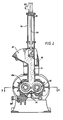
- Figure 1 is a schematic view illustrating the overall mixing machine in vertical section.
- Figure 2 is a vertical section through the lower portion of the machine illustrated in Figure 1, and shows the ram in its down position.
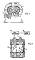
- Figure 3 is a horizontal section taken generally on the line 3-3 of Figure 1.
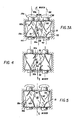
- Figure 3A is a schematic view of the relationship between the two counter-rotating rotors in the preferred alignment pursuant to the present invention.
- Figure 4 is a view similar to Figure 3A but taken at a slightly later instant of time wherein both rotors have turned through 90 degrees relative to the position illustrated in Figure 3A.
- Figure 5 is a view similar to Figures 3A and 4, but illustrating the rotors after a further 90 degrees of rotation, that is after having rotated 180 degrees from the Figure 3A positions.
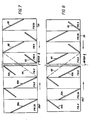
- Figure 6 illustrates in schematic fashion, the orientation of the rotor wings in the views of Figures 3A by unwrapping the cylindrical envelope which contains the rotor wings.
- Figure 7 is a view similar to Figure 6 but illustrating the rotor wing orientations after 90 degrees of rotation for the rotors, and corresponds to Figure 4.
- Figure 8 is a view similar to Figures 6 and 7 but illustrating the rotor wings 90 degrees beyond the position of Figure 7 and 180 degrees beyond the position of Figure 6, and corresponds to Figure 5.
- Figure 9 is a graphical presentation of the effect on rotor productivity (Kg/hr) of departing slightly from 0° alignment of the rotors, that is with one rotor provided in a different angular relationship from the zero degree relationship suggested in Figures 3A, 4 and 5.
- Figure 10 is a graphical presentation of the effect on mix viscosity of slight non-alignment between the rotors as suggested in Figure 9, both Figure 9 and 10 having the same horizontal units of rotor rotational alignment (that is, 0° alignment +/- non-alignment).
- Figures 1 and 2 show a mixing machine including a vertically reciprocable ram 10 movable between the position shown in Figure 1 and the position shown in Figure 2 to move a batch of ingredients to be mixed from a charging chamber 11 into a mixing chamber 17.
- Two counter-rotating rotors 13 and 13a have wings that act on these ingredients to achieve a thorough mixing thereof.
- US-A-3,610,585 and to US-A-2,962,186 issued November 29, 1960 to C.F. Gottschalk, for a more complete description of the general aspects of such a mixing machine.
- the ingredients are initially introduced to hopper 15 while the ram 10 is in its raised position ( Figure 1) so that the ingredients drop downwardly into the chamber 11 where they are compressed and fed into the mixing chamber 17 by the ram 10.
- a hinged door 14 opposite the ram 10 is opened to withdraw the mixed materials.
- a locking device 25 is provided for securing the door 14 in place during mixing process.
- the ram 10 is preferably operated by a vertically reciprocable fluid motor in the form of actuator 16 having a piston 18 provided in a cylinder for movement of actuating rod 20.
- the ram 10 is attached to the lower end of actuating rod 20 externally of cylinder 16 and air pressure is selectively provided to line 22 for urging the piston downwardly from the Figure 1 position to the Figure 2 position.
- the ram 10 is retracted by air pressure to the opposite side of piston 18.
- rotors 13 and 13a are driven in opposite directions by a conventional gear mechanism 24 through drive motor 26.
- the gear mechanism 24 may comprise identical gears where the rotors are to be driven at the same speed, or in the alternative, a typical mixer generally has so-called friction ratio gears that permit the rotors to be driven at different speeds.
- the gear mechanism 24 serves solely to drive the rotors 13 and 13a at the same speed and at opposite directions so as to realize the advantages of the present invention.
- Drive motor 26 may be of conventional configuration, and preferably includes suitable means for varying the speed of rotation for the rotors, said speeds being dictated in large part by the ingredients being mixed.
- non-intermeshing rotors 13 and 13a are driven in opposite directions as indicated by the arrows 28 and 28a, respectively in Figure 3A, such that diagonally opposed long wings 32 and 32a are arranged in opposed pairs to act on the mix in the window defined by the horizontal plane of the rotor axes 30 and 30a.
- the improved mixing is achieved in that the wings not only achieve a transverse or extensive mixing whereby the ingredients are urged from one parti-cylindrical cavity portion of the mixing chamber to the other, but intensified mixing is achieved as a result of squeezing of the mix axially toward the center of the mixing chamber 40 (where the center 40 is defined by the intersection between two diagonals 42 and 44 of a rectangle defined by the end walls 36 and 38 and by the rotor axes 30 and 30a).
- One such diagonal 42 has the paired rotor wings 32 and 32a provided on opposite sides thereof in Figure 3A, that is in a position for the rotors referred to hereinafter as a reference or zero degree position.
- the combination of transverse and axial squeeze mixing is illustrated in Figure 3A by the four force diagrams illustrating the tendency for the rotor wings 32 and 32a to achieve movement of the mix generally toward the one diagonal 42 defined above. Also, material at the center of the mixer is moved by the wings into the parti-cylindrical cavities to be mixed by a shearing action.
- a second pair of rotor wings 52 and 52a in each of the rotors 13 and 13a, respectively, are provided with their leading ends located in an axial plane defined by the trailing ends of the one pair of rotors 32 and 32a referred to previously. More particularly, this second pair of rotor wings 52 and 52a are provided at least 90 degrees behind the one longer pair referred to in the preceding paragraphs. These shorter rotor wings 52 and 52a act on the mix in substantially the same manner as the longer wings 32 and 32a described above.
- Each of these shorter wings 52 and 52a has its leading end adapted to simultaneously intersect the reference plane defined by the axes 30 and 30a at a point in time when the longer rotor wings 32 and 32a have passed through the reference plane and this next portion of the rotor cycle is illustrated in Figure 4. Note that these shorter rotor wings 52 and 52a are oriented on opposite sides of the second diagonal 44 referred to previously with reference to Figure 3A. Similar diagrams are also provided in Figure 4 to illustrate the fact that the mix is acted on by the wings so as to impart both transverse and axial flow directions whereby transverse and intensive mixing are achieved.
- Figures 3A, 4 and 5 represent positions for the horizontally opposed rotors and more particularly of the rotor wings at 90 degree intervals during a portion of the 360 degrees of rotation for these rotors.
- the cycle of rotor rotation is repeated for each revolution of the rotors.
- this cycle of window geometry defined by the wings and the body portions of the rotors in the area of the horizontal reference plane will repeat itself twice during each such rotor revolution cycle.
- Figure 5 illustrates the configuration for the rotors 13 and 13a after 180 degrees of rotor rotation and, although Figure 5 is identical to Figure 3A, it is noted that the longer rotor wings 62 and 62a occupy the same positions as did the long one pair rotor wings and 32 and 32a in Figure 3A.
- FIG. 6 The repetitive window geometry between the opposed rotors achieved by the rotor wing configuration of the present invention is illustrated graphically in Figures 6, 7 and 8.
- the various frames illustrated in these views correspond to the rotor positions illustrated 3A, 4 and 5 and such frames are appropriately annotated in Figures 6, 7 and 8 for clarity.
- the two adjacent frames illustrated at 35 and 35a on opposite sides of the mixer center line 39 shows schematically the long rotor wings 32 and 32a arranged at opposite sides of the diagonal 42.
- the adjacent frames are to illustrate the configuration for the other wings 52 and 52a discussed previously with reference to Figure 4 and 62 and 62a discussed above with reference to Figure 5.
- Figure 7 simply shows the frames 35 and 35a having moved away from the center window defined by the opposed rotors and instead said window having been defined by the rotor wings 52 and 52a arranged at opposite sides of the second diagonal 44 as referred to previously.
- Figure 8 illustrates another successive 90 degrees of rotation from that of Figure 7 wherein the center frames define the variable geometry window as a result of downward movement for the rotor wings 62 and 62a.
- Figure 6 corresponds to Figure 3A, Figure 7 to Figure 4, and Figure 8 to Figure 5 in terms of the orientation for the rotors 13 and 13a and more particularly of these wings in these various views.
- Figures 9 and 10 must be interpreted together, and these graphical presentations illustrate qualitatively the results achieved by aligning the rotors as described above and rotating them at the same speeds to provide the cylindircally repeatable window geometry in the mixing chamber.
- Figures 9 and 10 show the level of productivity and the viscosity level achieved with the rotors turning at different speeds relative to one another (more particularly, with a friction ratio of 1.12 to 1).
- Figure 10 shows that the reduction in viscosity(at zero degree rotor alignment)is best.
- the combined results of tests for both viscosity and productivity show that the advantages of the present invention can be realized if only the rotors are close to the zero degree alignment referred to above. More specifically, the rotors should be within their +/- 20 degrees of this zero degree orientation for best results.
Landscapes
- Engineering & Computer Science (AREA)
- Mechanical Engineering (AREA)
- Chemical & Material Sciences (AREA)
- Chemical Kinetics & Catalysis (AREA)
- Processing And Handling Of Plastics And Other Materials For Molding In General (AREA)
- Mixers Of The Rotary Stirring Type (AREA)
Claims (6)
deux rotors de mélange (13,13a), opposés et non-engrenés l'un dans l'autre, chacun desdits rotors étant prévu dans une cavité respective, chaque rotor présentant au moins deux ailettes (32,32a,52,52a), en forme générale hélicoïdale, chaque ailette présentant une extrémité avant (34,34a) et une extrémité arrière, chaque extrémité arrière étant espacée circonférentiellement à l'arrière de son extrémité avant de la valeur d'un angle (α) par rapport au sens de direction du rotor, ledit procédé de mélange comprenant les étapes consistant à :
entraîner lesdits rotors seulement à une vitesse égale dans des sens opposés sur des axes horizontaux parallèles (30,30a),
orienter lesdits rotors l'un par rapport à l'autre suivant une relation de positionnement en rotation prédéterminée,
ledit positionnement en rotation prédéterminé étant situé dans la plage de ± 20° par rapport à l'alignement à 0° des extrémités avant des premières ailettes de rotor,
placer une première desdites ailettes de rotor, sur chaque rotor, pour servir de premier couple d'ailettes de rotor opposées (32,32a), déplacer ledit premier couple d'ailettes de rotor opposées à une vitesse de rotor égale, en passant dans un rectangle de référence horizontal, défini par lesdits axes de rotor et lesdites deux parois d'extrémité, ledit premier couple d'ailettes de rotor opposées se déplaçant dans ledit rectangle, sur des côtés opposés par rapport à une première diagonale (42) dudit rectangle, avec lesdites extrémités avant de ladite première paire d'ailettes de rotor opposées adjacentes respectivement aux parois d'extrémité et se déplaçant dans ledit rectangle, sensiblement au même moment, pour produire un mélange avec malaxage transversal et axial des ingrédients, entre ledit premier couple d'ailettes de rotor opposées,
ledit mélange à malaxage transversal et axial entre ledit premier couple d'ailettes de rotor opposées étant effectué en direction de ladite première diagonale, par rapport aux côtés opposés de ladite première diagonale, placer une seconde desdites ailettes de rotor (52,52a) sur chaque rotor, pour servir de second couple d'ailettes de rotor opposées, lesdits premier et second couple d'ailettes de rotor présentant leurs extrémités avant respectives en position angulaire en quinconce par rapport à la machine, ladite seconde paire d'ailettes de rotor opposées passant dans ledit rectangle sur les côtés opposés d'une seconde diagonale (44) dudit rectangle, avec lesdites extrémités avant dudit second couple d'ailettes de rotor opposées adjacentes respectivement aux parois d'extrémité et se déplaçant dans ledit rectangle sensiblement au même moment,
ledit second moment étant situé à un moment ultérieur au moment où le premier couple d'ailettes de rotor opposées sont passées dans ledit rectangle, pour mélanger avec malaxage transversal et axial les ingrédients, entre ledit second couple d'ailettes de rotor opposées, en se déplaçant dans ledit rectangle, et
ledit mélange avec malaxage transversal et axial, entre ledit second couple d'ailettes de rotor opposées s'effectuant vers ladite seconde diagonale, en partant des côtés opposés de ladite seconde diagonale,
de manière que ledit mélange à malaxage transversal et axial partant des côtés opposés de ladite première diagonale et des côtés opposés de ladite seconde diagonale soit chaque fois répété à chaque rotation des deux rotors.
placer une troisième ailette de forme hélicoïdale sur chaque rotor, chaque ailette présentant une extrémité avant et une extrémité arrière, avec ladite troisième ailette sur chaque rotor, placée à l'opposé de la première ailette sur le rotor et avec la quatrième ailette sur chaque rotor placée à l'opposé de la seconde ailette sur le rotor,
lesdites troisièmes ailettes des rotors, servant de troisième couple (62,62a) d'ailettes de rotor opposées, passant dans le rectangle à une vitesse de rotor égale et sur les côtés opposés de ladite première diagonale, avec leurs extrémités avant adjacentes respectivement aux parois d'extrémité et se déplaçant dans ledit rectangle à approximativement une troisième fois lorsque chacun desdits rotor a tourné de 180° par rapport à sa position respective audit premier moment, pour produire un mélange à malaxage transversal et axial des ingrédients, entre ledit troisième couple de côtés opposés de ladite première diagonale,
ledit mélange à malaxage transversal et axial entre ledit troisième couple d'ailettes de rotor opposées s'effectuant en direction de ladite première diagonale, en partant des côtés opposés de ladite première diagonale,
lesdites quatrième ailettes des rotors, servant de quatrième paire d'ailette de rotor opposées, passant dans le rectangle à une vitesse égale à celle du rotor, sur les côtés opposés de ladite seconde diagonale, avec leurs extrémités avant adjacentes respectivement aux parois d'extrémité et se déplaçant dans ledit rectangle à peu près une quatrième fois, pour produire un mélange à malaxage axial et transversal, entre ledit quatrième couple d'ailettes de rotor opposées qui se déplace dans ledit rectangle, sur les côtés opposés de ladite seconde diagonale,
ledit mélange avec malaxage transversal et axial, entre ledit quatrième couple d'ailettes de rotor opposées s'effectuant vers ladite seconde diagonale, en partant des côtés opposés de ladite seconde diagonale,
de manière que ledit mélange à malaxage transversal et axial partant des côtés opposés de ladite première diagonale et des côtés opposés de ladite seconde diagonale soit chaque fois répété deux fois à chaque rotation des deux rotors.
Applications Claiming Priority (2)
| Application Number | Priority Date | Filing Date | Title |
|---|---|---|---|
| US864096 | 1986-05-16 | ||
| US06/864,096 US4893936A (en) | 1986-05-16 | 1986-05-16 | Mixing machine with non-intermeshing pair of rotors driven solely at the same rotor speed in opposite directions and having a predetermined rotational alignment relationship between the two counter-rotating rotors |
Publications (2)
| Publication Number | Publication Date |
|---|---|
| EP0246044A1 EP0246044A1 (fr) | 1987-11-19 |
| EP0246044B1 true EP0246044B1 (fr) | 1991-09-04 |
Family
ID=25342522
Family Applications (1)
| Application Number | Title | Priority Date | Filing Date |
|---|---|---|---|
| EP87304136A Expired - Lifetime EP0246044B1 (fr) | 1986-05-16 | 1987-05-08 | Procédé de malaxage |
Country Status (9)
| Country | Link |
|---|---|
| US (1) | US4893936A (fr) |
| EP (1) | EP0246044B1 (fr) |
| JP (1) | JPH0634913B2 (fr) |
| KR (1) | KR950004143B1 (fr) |
| CN (1) | CN1009165B (fr) |
| AU (1) | AU584510B2 (fr) |
| BR (1) | BR8702683A (fr) |
| DE (1) | DE3772619D1 (fr) |
| ES (1) | ES2026532T3 (fr) |
Families Citing this family (23)
| Publication number | Priority date | Publication date | Assignee | Title |
|---|---|---|---|---|
| US4744668A (en) * | 1986-10-14 | 1988-05-17 | Farrel Corporation | Internal batch mixing machines with non-intermeshing rotors of increased performance |
| US4834543A (en) * | 1988-04-12 | 1989-05-30 | Farrel Corporation | Optimized four-wing, non-intermeshing rotors for synchronous drive at optimum phase relation in internal batch mixing machines |
| JPH02269011A (ja) * | 1989-04-11 | 1990-11-02 | Masao Moriyama | 混練機 |
| JPH02269010A (ja) * | 1989-04-11 | 1990-11-02 | Masao Moriyama | 混練機ロータ |
| JP2922684B2 (ja) * | 1991-09-06 | 1999-07-26 | 株式会社神戸製鋼所 | 密閉式混練機 |
| US5376849A (en) * | 1992-12-04 | 1994-12-27 | International Business Machines Corporation | High resolution programmable pulse generator employing controllable delay |
| FR2736561A1 (fr) * | 1995-07-13 | 1997-01-17 | Michelin & Cie | Melangeur interne a rotors de type tangentiel |
| JP3135056B2 (ja) * | 1996-12-19 | 2001-02-13 | 株式会社神戸製鋼所 | 密閉型混練装置 |
| KR20010042228A (ko) | 1998-03-28 | 2001-05-25 | 스키너 엔진 컴퍼니 | 내부 배치식 믹싱 머신 및 로터 |
| JP2000246731A (ja) * | 1999-03-02 | 2000-09-12 | Kobe Steel Ltd | 混練ロータとこれを有する混練機 |
| US6494607B2 (en) | 2001-05-04 | 2002-12-17 | Farrel Corporation | Four wing, non-intermeshing rotors for synchronous drive to provide improved dispersive and distributive mixing in internal batch mixers |
| JP4256330B2 (ja) * | 2004-11-18 | 2009-04-22 | 株式会社神戸製鋼所 | 密閉式混練機およびそれに用いられている混練ロータ |
| US7476017B2 (en) * | 2005-09-29 | 2009-01-13 | Jacques Mortimer | Intermeshing kneader with tilting mixing chamber |
| JP4568785B2 (ja) * | 2009-01-19 | 2010-10-27 | 株式会社神戸製鋼所 | 混練ロータ |
| JP4542605B1 (ja) * | 2009-04-15 | 2010-09-15 | 株式会社神戸製鋼所 | 密閉式混練機及び混練ロータ |
| CN101757866B (zh) * | 2010-02-11 | 2012-04-25 | 黄建军 | 卧式四轴搅拌机 |
| JP5792650B2 (ja) * | 2012-01-31 | 2015-10-14 | 株式会社神戸製鋼所 | 混練ロータ、およびそれを備える密閉式混練機 |
| CN108191018B (zh) * | 2018-01-02 | 2019-07-23 | 武汉怡清环保工程有限责任公司 | 一种工业废水反应池 |
| CN108101182B (zh) * | 2018-01-02 | 2019-02-15 | 济南泰德天成环境科技有限公司 | 一种污水处理池 |
| DE102018201482A1 (de) * | 2018-01-31 | 2019-08-01 | Harburg-Freudenberger Maschinenbau Gmbh | Innenmischer |
| JP6964037B2 (ja) * | 2018-04-09 | 2021-11-10 | 株式会社神戸製鋼所 | 混練ロータ |
| CN110682459A (zh) * | 2019-10-25 | 2020-01-14 | 芜湖市智睿包装制品有限公司 | 一种塑料包装盒原料熔炼装置 |
| CN112123826B (zh) * | 2020-09-08 | 2022-05-24 | 浙江中天能橡胶股份有限公司 | 一种高性能输送带的制造方法 |
Family Cites Families (11)
| Publication number | Priority date | Publication date | Assignee | Title |
|---|---|---|---|---|
| US2962186A (en) * | 1958-01-07 | 1960-11-29 | Farrel Birmingham Co Inc | Discharge door for rubber mixers |
| US3610585A (en) * | 1970-03-18 | 1971-10-05 | Usm Corp | Mixer |
| JPS4943330U (fr) * | 1972-07-14 | 1974-04-16 | ||
| US4084263A (en) * | 1973-04-30 | 1978-04-11 | Firma Werner & Pfleiderer | Kneading and mixing machine |
| DD125478A5 (fr) * | 1974-12-11 | 1977-04-20 | ||
| GB2027600B (en) * | 1978-06-23 | 1982-08-11 | Kobe Steel Ltd | Mixing and kncading machine |
| IT1191304B (it) * | 1978-06-23 | 1988-03-07 | Kobe Steel Ltd | Macchina per la mescola e impastatrice |
| DE2836940C2 (de) * | 1978-08-24 | 1982-04-08 | Werner & Pfleiderer, 7000 Stuttgart | Innenmischer zum Kneten von plastischen Massen, insbesondere von Gummi |
| JPS5931369B2 (ja) * | 1980-02-16 | 1984-08-01 | 株式会社神戸製鋼所 | 密閉型混練捏和装置のロ−タ |
| SU882769A1 (ru) * | 1980-03-31 | 1981-11-23 | Предприятие П/Я Г-4913 | Ротор к смесителю типа "бенбери |
| DE3035353C2 (de) * | 1980-09-19 | 1985-01-03 | Werner & Pfleiderer, 7000 Stuttgart | Verfahren zum Steuern des Mischvorganges von Kautschukmischungen in einem Innenmischer |
-
1986
- 1986-05-16 US US06/864,096 patent/US4893936A/en not_active Expired - Fee Related
-
1987
- 1987-05-08 ES ES198787304136T patent/ES2026532T3/es not_active Expired - Lifetime
- 1987-05-08 EP EP87304136A patent/EP0246044B1/fr not_active Expired - Lifetime
- 1987-05-08 DE DE8787304136T patent/DE3772619D1/de not_active Expired - Lifetime
- 1987-05-13 AU AU72794/87A patent/AU584510B2/en not_active Ceased
- 1987-05-14 KR KR1019870004745A patent/KR950004143B1/ko not_active Expired - Fee Related
- 1987-05-15 JP JP62118723A patent/JPH0634913B2/ja not_active Expired - Lifetime
- 1987-05-15 CN CN87103521A patent/CN1009165B/zh not_active Expired
- 1987-05-15 BR BR8702683A patent/BR8702683A/pt not_active IP Right Cessation
Also Published As
| Publication number | Publication date |
|---|---|
| KR870010896A (ko) | 1987-12-18 |
| CN87103521A (zh) | 1988-01-27 |
| CN1009165B (zh) | 1990-08-15 |
| JPS62279831A (ja) | 1987-12-04 |
| KR950004143B1 (ko) | 1995-04-27 |
| JPH0634913B2 (ja) | 1994-05-11 |
| AU7279487A (en) | 1987-11-19 |
| BR8702683A (pt) | 1988-11-29 |
| DE3772619D1 (de) | 1991-10-10 |
| US4893936A (en) | 1990-01-16 |
| ES2026532T3 (es) | 1992-05-01 |
| AU584510B2 (en) | 1989-05-25 |
| EP0246044A1 (fr) | 1987-11-19 |
Similar Documents
| Publication | Publication Date | Title |
|---|---|---|
| EP0246044B1 (fr) | Procédé de malaxage | |
| EP0340888B1 (fr) | Rotors à quattre lobes pour mélangeur-malaxeurs | |
| KR960010200B1 (ko) | 내부 배치 혼합기 | |
| JP4195614B2 (ja) | バッチ式密閉式混合機中で改良された分散的及び分配的混合を提供する為の同調駆動用四つ羽根非かみ合いローター | |
| KR940011562B1 (ko) | 내부 뱃치 혼합기용 2날개 비교합 로우터들 및 그 작동방법 | |
| KR20010042228A (ko) | 내부 배치식 믹싱 머신 및 로터 | |
| AU2002245544A1 (en) | Four wing, non-intermeshing rotors for synchronous drive to provide improved dispersive and distributive mixing in internal batch mixers | |
| EP0262917A2 (fr) | Mélangeurs | |
| US3742724A (en) | Ice cream machine | |
| EP1005604A1 (fr) | Machine a piston rotatif | |
| US2630274A (en) | Comminuting machine with opposed and axially oscillated rotors | |
| RU2049666C1 (ru) | Смеситель-активатор | |
| DE19734783C2 (de) | Rotationskolben-Brennkraftmaschine | |
| DE2913216C2 (de) | Mittelachsige Rotationskolbenmaschine als Verbundmaschine | |
| DE4025406A1 (de) | Rotationslaeufermaschine | |
| DE2448982A1 (de) | Ls pumpe oder motor arbeitende drehkolbenmaschine | |
| CA2119171C (fr) | Procede pour melanger des matieres granuleuses, en poudre et liquides et melangeur utilise a ces fins | |
| EP0615781A1 (fr) | Procédé pour le mélange en continu des granulés et/ou poudres et/ou liquides et dispositif pour réaliser le procédé | |
| JPS63130128A (ja) | 混練押出し装置 | |
| DE4337427A1 (de) | Statorgeometrie einer Rotations-Kolbenmaschine | |
| DE102018103446A1 (de) | Vorrichtung und Verfahren zum Verdichten und/oder Verdrängen eines Fluids |
Legal Events
| Date | Code | Title | Description |
|---|---|---|---|
| PUAI | Public reference made under article 153(3) epc to a published international application that has entered the european phase |
Free format text: ORIGINAL CODE: 0009012 |
|
| AK | Designated contracting states |
Kind code of ref document: A1 Designated state(s): BE DE ES FR GB IT NL SE |
|
| 17P | Request for examination filed |
Effective date: 19880510 |
|
| 17Q | First examination report despatched |
Effective date: 19890809 |
|
| GRAA | (expected) grant |
Free format text: ORIGINAL CODE: 0009210 |
|
| AK | Designated contracting states |
Kind code of ref document: B1 Designated state(s): BE DE ES FR GB IT NL SE |
|
| REF | Corresponds to: |
Ref document number: 3772619 Country of ref document: DE Date of ref document: 19911010 |
|
| ITF | It: translation for a ep patent filed | ||
| ET | Fr: translation filed | ||
| REG | Reference to a national code |
Ref country code: ES Ref legal event code: FG2A Ref document number: 2026532 Country of ref document: ES Kind code of ref document: T3 |
|
| PLBE | No opposition filed within time limit |
Free format text: ORIGINAL CODE: 0009261 |
|
| STAA | Information on the status of an ep patent application or granted ep patent |
Free format text: STATUS: NO OPPOSITION FILED WITHIN TIME LIMIT |
|
| 26N | No opposition filed | ||
| EAL | Se: european patent in force in sweden |
Ref document number: 87304136.2 |
|
| PGFP | Annual fee paid to national office [announced via postgrant information from national office to epo] |
Ref country code: FR Payment date: 20000419 Year of fee payment: 14 |
|
| PGFP | Annual fee paid to national office [announced via postgrant information from national office to epo] |
Ref country code: SE Payment date: 20000420 Year of fee payment: 14 Ref country code: GB Payment date: 20000420 Year of fee payment: 14 Ref country code: DE Payment date: 20000420 Year of fee payment: 14 |
|
| PGFP | Annual fee paid to national office [announced via postgrant information from national office to epo] |
Ref country code: NL Payment date: 20000427 Year of fee payment: 14 |
|
| PGFP | Annual fee paid to national office [announced via postgrant information from national office to epo] |
Ref country code: BE Payment date: 20000512 Year of fee payment: 14 |
|
| PGFP | Annual fee paid to national office [announced via postgrant information from national office to epo] |
Ref country code: ES Payment date: 20000608 Year of fee payment: 14 |
|
| PG25 | Lapsed in a contracting state [announced via postgrant information from national office to epo] |
Ref country code: GB Free format text: LAPSE BECAUSE OF NON-PAYMENT OF DUE FEES Effective date: 20010508 |
|
| PG25 | Lapsed in a contracting state [announced via postgrant information from national office to epo] |
Ref country code: SE Free format text: LAPSE BECAUSE OF NON-PAYMENT OF DUE FEES Effective date: 20010509 Ref country code: ES Free format text: LAPSE BECAUSE OF NON-PAYMENT OF DUE FEES Effective date: 20010509 |
|
| PG25 | Lapsed in a contracting state [announced via postgrant information from national office to epo] |
Ref country code: BE Free format text: LAPSE BECAUSE OF NON-PAYMENT OF DUE FEES Effective date: 20010531 |
|
| BERE | Be: lapsed |
Owner name: FARREL CORP. Effective date: 20010531 |
|
| PG25 | Lapsed in a contracting state [announced via postgrant information from national office to epo] |
Ref country code: NL Free format text: LAPSE BECAUSE OF NON-PAYMENT OF DUE FEES Effective date: 20011201 |
|
| GBPC | Gb: european patent ceased through non-payment of renewal fee |
Effective date: 20010508 |
|
| PG25 | Lapsed in a contracting state [announced via postgrant information from national office to epo] |
Ref country code: FR Free format text: LAPSE BECAUSE OF NON-PAYMENT OF DUE FEES Effective date: 20020131 |
|
| NLV4 | Nl: lapsed or anulled due to non-payment of the annual fee |
Effective date: 20011201 |
|
| PG25 | Lapsed in a contracting state [announced via postgrant information from national office to epo] |
Ref country code: DE Free format text: LAPSE BECAUSE OF NON-PAYMENT OF DUE FEES Effective date: 20020301 |
|
| REG | Reference to a national code |
Ref country code: ES Ref legal event code: FD2A Effective date: 20030203 |
|
| PG25 | Lapsed in a contracting state [announced via postgrant information from national office to epo] |
Ref country code: IT Free format text: LAPSE BECAUSE OF NON-PAYMENT OF DUE FEES;WARNING: LAPSES OF ITALIAN PATENTS WITH EFFECTIVE DATE BEFORE 2007 MAY HAVE OCCURRED AT ANY TIME BEFORE 2007. THE CORRECT EFFECTIVE DATE MAY BE DIFFERENT FROM THE ONE RECORDED. Effective date: 20050508 |