EP0245673A2 - Procédé et dispositif de mesure de la densité d'un liquide - Google Patents
Procédé et dispositif de mesure de la densité d'un liquide Download PDFInfo
- Publication number
- EP0245673A2 EP0245673A2 EP87105799A EP87105799A EP0245673A2 EP 0245673 A2 EP0245673 A2 EP 0245673A2 EP 87105799 A EP87105799 A EP 87105799A EP 87105799 A EP87105799 A EP 87105799A EP 0245673 A2 EP0245673 A2 EP 0245673A2
- Authority
- EP
- European Patent Office
- Prior art keywords
- liquid
- membrane
- bellows
- determined
- tube
- Prior art date
- Legal status (The legal status is an assumption and is not a legal conclusion. Google has not performed a legal analysis and makes no representation as to the accuracy of the status listed.)
- Withdrawn
Links
Images
Classifications
-
- G—PHYSICS
- G01—MEASURING; TESTING
- G01N—INVESTIGATING OR ANALYSING MATERIALS BY DETERMINING THEIR CHEMICAL OR PHYSICAL PROPERTIES
- G01N9/00—Investigating density or specific gravity of materials; Analysing materials by determining density or specific gravity
- G01N9/26—Investigating density or specific gravity of materials; Analysing materials by determining density or specific gravity by measuring pressure differences
Definitions
- the invention relates to a method and a device for measuring the density of a liquid with a sensor which is arranged within the liquid and determines the frequency of an oscillator.
- the object of the invention is to improve a method and a device for measuring the density of a liquid so that the smallest differences in density can be measured exactly and the measurement results are not changed by external influences, in particular by changes in temperature.
- This object is achieved in that the liquid pressure of the liquid to be determined and a reference liquid are measured, and the difference in the pressures changes the tensile stress of a mechanically oscillatable element, the frequency of which is used as a measure of the density of the liquid to be determined.
- the density can be measured by this method and by this device, but also all physical quantities which can be derived from the density, such as e.g. B. the acidity, the original wort, the sugar content, the fat content or the carbon dioxide content of a liquid.
- the pressure of the determining liquid on one side of a membrane or the bellows and the reference liquid on the other side of a membrane or the bellows, and that the vibratable element is attached to the membrane or the bellows directly or by transmission parts This leads to a particularly simple and unaffected construction.
- the pressure of the two liquids can be applied to one side of the membrane or the bellows by means of a transmission liquid that is applied to one side of a second membrane or a second bellows, on the second side of which the liquid to be determined or the reference liquid is applied.
- the pressure of the liquid to be determined is on one side of a first membrane or a bellows and the reference liquid on the opposite side of a second membrane or a second bellows, and that the oscillatable element is tensioned between the membranes or the bellows is.
- Such a construction does not allow temperature differences and therefore material expansions acting on the measuring device to be included in the measurements as falsifying values.
- a particularly simple manufacture and easy accessibility of the oscillatable element for repairs and for replacement is achieved in that the oscillatable element lies in a tube filled with gas, in particular air, which is closed on one side and the oscillatable element on one side with one end is fixed, and that the oscillatable element is fixed at its other end to the membrane or the bellows.
- gas in particular air
- the membrane on which the liquid to be determined rests is parallel to the direction of flow of the liquid to be determined. In this way it is avoided that the liquid to be measured forms a back pressure on the membrane to which this liquid is present, which falsifies the measurement result.
- the reference liquid always has the same temperature as the liquid to be measured
- the reference liquid be in a vertical pipe, in particular, which lies within the liquid to be determined.
- the vertical tube filled with reference liquid can also be connected to the interior of a bellows filled with the reference liquid, which bellows lies within the liquid to be determined. This ensures that the reference liquid cannot mix with the liquid to be measured and is nevertheless always exposed to the temperature of the liquid to be measured.
- the oscillatable element flows through current and is part of a resonant circuit.
- the vibratable element can traverse a magnetic field and vibrate due to the fluctuations in the current flowing through it.
- the magnetic field be generated by electromagnets, in particular permanent magnets, arranged on the side of the element.
- the oscillatable element is an elongated part of low bending strength made of electrically conductive material, in particular a string, a wire, a tube, a film or a resilient element.
- the vibratable element can also be electrically be connected to a measuring instrument which forms the second component of the resonant circuit and indicates the respective frequency and thus the liquid density.
- a simple, very precisely measuring device is achieved when the oscillatable element is clamped between two membranes, each of which separates the two liquids.
- a particularly easy to install on the outside and easy to maintain and repair is created in that the liquid to be determined is passed through a pipe, housing or container, the wall of which has at least one opening in which a membrane or a bellows is attached or connected is. It is advantageous here if there are two openings in the wall, a first membrane being attached to the first opening, the liquid to be determined being present on the front side and the reference liquid being present on the rear side, and a second membrane being attached to the second opening is on the front of which the liquid to be determined is present and the back of which is directly or indirectly connected to the mechanically oscillatable element which is further influenced by the reference liquid. It is also advantageous if housings are fastened to the outside of the wall openings and are closed by a cover, in particular a clamping nut, which presses a device carrying the membrane (s) against the opening edge.
- the inside of the devices carrying the membrane (s) are connected via a line which runs outside the tube, housing or container.
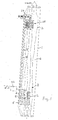
- a vertical tubular housing 1 is interposed in a pipeline, not shown, which contains the liquid to be measured.
- this liquid flows from bottom to top and the housing 1 has a larger cross section than the liquid line, since a measuring device 2 is used in the housing 1, which reduces the flow cross section of the housing 1, so that the larger cross section of the housing 1 for this it is ensured that the flow cross-section of the housing is not smaller than that of the pipeline.
- a pipe 3 is attached to the side, running parallel to the axis, around which the liquid 4 to be measured flows and the diameter of which is many times smaller than that of the housing 1.
- a reference liquid 5 which is similar to that to be measured Liquid 4 is. Is z.
- the reference liquid can be water.
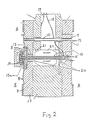
- the tube 3 opens into a chamber 6, of which a vertical wall 7 carries a vertical membrane 8 in a cutout.
- the reference liquid 5 is thus on one side of the membrane.
- a membrane 8 Transmission liquid 9 in particular in the form of thin oil.
- the rear space to the membrane 8 is connected via a line 10 to a space 11 in which the transmission liquid 9 is also located.
- This space 11 is delimited on the side facing away from the membrane 8 by a second membrane 12 which is parallel to membrane 8, so that this membrane lies parallel to the direction of flow of the liquid 4.
- the liquid 4 is thus on the outside of the membrane 12, so that differences in the hydrostatic pressure acting on the outside of the membrane 12 from the liquid 4 are transmitted through the liquid 9 via the line 10 to the inside of the membrane 8.
- the membrane 8 Since the inside of the membrane 8 is thus exposed to the hydrostatic pressure of the liquid 4 to be measured and the outside of the membrane 8 to the hydrostatic pressure of the reference liquid 5, the membrane 8 is moved in accordance with the difference between these two liquids 4 and 5. It is important here that the hydrostatic pressure of the reference liquid is constant, since the height h of the liquid column of the reference liquid 5 is always constant and the specific weight ⁇ 1 does not change. The height h of the reference liquid also represents the measuring height for the liquid 4 to be measured. In contrast, the specific weight ⁇ 2 of the liquid 4 to be measured changes due to its different density.
- the pressure difference ⁇ P applied to the membrane 8 is thus (hx ⁇ 2) - (hx ⁇ 1), with this formula only the value ⁇ 2 changing, so that the pressure difference measurable on the membrane 8 is directly a value for the specific Weight ⁇ 2 of the liquid to be measured and thus its density.
- ⁇ P corresponds to ⁇ 2.
- the hydrostatic pressures (hx ⁇ 1) and (hx ⁇ 2) superimposed, many times higher, process pressure acts in equally on both sides of the membrane 8 and thus cancels itself out.
- This measuring device 11 has an oscillatable element 13, in particular in the form of an oscillating wire, which is stretched between two points.
- the first end 13a of the wire 13 is fastened to the membrane 8 in its center, this fastening point being formed by a device 13a which is an overload protection device.
- the device 13a has a resilient element 14.
- the end of the element 13 is fastened to a cylindrical part 15 which closes a metal tube 16 at one end.
- the element 13 lies coaxially in this metal tube 16, the other end of the horizontal metal tube 16 facing the membrane 8 being fixed immovably in the housing 17 of the lower measuring device 11.
- the metal tube 16 is filled with a gas, in particular air, in which the element 13 vibrates.
- the element 13 is flowed through by electrical current and is part of an oscillating circuit, an electrical line 18 being connected to the part 15 and a second electrical line 19 to the housing 17. Since the metal tube 16 and the part 15 are supported relative to the housing 17 by insulating bushes or rings 20, the current connected via the line 19 can reach the element 13 via the housing 17 only via the device 13 or the membrane 8.
- the metal tube 16 traverses inside the housing 17 an inner chamber 21, in which a permanent magnet 22 is fixed, which surrounds the metal tube 16.
- the wire-shaped element 13 is thus part of an electrical resonant circuit, the frequency of the Vibrations of the element 13 is determined by its tension, which in turn is determined by the tensile force generated by the membrane 8.
- the lines 18 and 19 lead to the outside to an electrical device 23, which is the second part of the resonant circuit.
- the resonant circuit is in turn part of an oscillator contained in the electrical device, the frequency of which depends on the voltage of the element 13.
- the mechanical vibrations of the element 13 are converted into an electrical alternating voltage signal via the induction by the magnet 22.
- the oscillator therefore indicates to the electrical device or an equivalent electrical device the frequency of the resonant circuit, which changes in accordance with the density of the liquid to be measured.
- This frequency signal can be amplified and converted in electrical devices in order to indicate values on a scale or a driving device which directly show the density of the liquid 4.
- the upper end of the tube 3 is closed and connected via a line 24 to the inside of a bellows 25, which is perpendicular with its axis and thus parallel to the axis of the housing 1 and lies within the liquid 4.
- the bellows 25 thus absorbs temperature-related changes in volume of the reference liquid, caused by fluctuations in the process temperature, in the tube 3, so that temperature fluctuations are superimposed on the hydrostatic pressures (hx ⁇ 1) and (hx ⁇ 2) and do not affect the pressure changes Impact membrane 8. This results in a complete temperature-compensated measurement of the density.
- the vibratable element can also be a string, a tube, a film or a resilient element instead of a wire be educated.
- the element 12 can be attached to the membrane 8 at one end and to the membrane 12 at its other end. In such an embodiment, the transmission liquid 9 and the line 10 may be missing.
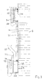
- the housing 1 can have an upper first opening 26 and a second opening 27 located below it in its wall 1a at different heights, into each of which the tubular socket-shaped housings 28 are welded coaxially.
- the housings 28 thus protrude from the outside of the housing 1 and are each closed on the outside by a tension nut 29 with a safety chain.
- the upper housing 28 there is a hollow circular disk-shaped carrier body 30, which is pressed against an inner flange of the housing 28 by a pressure cone or a spherical section on the inside of the clamping nut 29.
- the inside of the body 30 at the first opening 26 forms a membrane 31, on the outside of which the liquid to be measured is present.
- the reference liquid which is connected via a line 31 to the hollow carrier body 32 of the second opening 27.
- This body 32 contains not only a membrane on the side facing the liquid 4 to be measured, but also inside the differential pressure sensor with a vibrating side including a second membrane or a second bellows according to the first embodiment. Therefore, an electrical connection 33 is also on the body 32 for electrical device 23 is provided.
- the operation of this second embodiment corresponds to the operation of the first embodiment.
- the upper membrane 31 takes over the function of the bellows 25 in the first exemplary embodiment and the lower membrane 34 the mode of operation of the membrane 12.
- the interior of the body 32 is not shown and corresponds to the embodiment according to FIG. 2.
Landscapes
- Physics & Mathematics (AREA)
- Health & Medical Sciences (AREA)
- Life Sciences & Earth Sciences (AREA)
- Chemical & Material Sciences (AREA)
- Analytical Chemistry (AREA)
- Biochemistry (AREA)
- General Health & Medical Sciences (AREA)
- General Physics & Mathematics (AREA)
- Immunology (AREA)
- Pathology (AREA)
- Measuring Volume Flow (AREA)
- Measuring Fluid Pressure (AREA)
- Investigating Or Analyzing Materials By The Use Of Electric Means (AREA)
Applications Claiming Priority (2)
| Application Number | Priority Date | Filing Date | Title |
|---|---|---|---|
| DE3616385 | 1986-05-15 | ||
| DE19863616385 DE3616385A1 (de) | 1986-05-15 | 1986-05-15 | Verfahren und vorrichtung zum messen der dichte einer fluessigkeit |
Publications (2)
| Publication Number | Publication Date |
|---|---|
| EP0245673A2 true EP0245673A2 (fr) | 1987-11-19 |
| EP0245673A3 EP0245673A3 (fr) | 1988-07-20 |
Family
ID=6300897
Family Applications (1)
| Application Number | Title | Priority Date | Filing Date |
|---|---|---|---|
| EP87105799A Withdrawn EP0245673A3 (fr) | 1986-05-15 | 1987-04-18 | Procédé et dispositif de mesure de la densité d'un liquide |
Country Status (3)
| Country | Link |
|---|---|
| EP (1) | EP0245673A3 (fr) |
| CN (1) | CN87103492A (fr) |
| DE (1) | DE3616385A1 (fr) |
Families Citing this family (1)
| Publication number | Priority date | Publication date | Assignee | Title |
|---|---|---|---|---|
| ES2907457T3 (es) | 2011-09-01 | 2022-04-25 | Microtech Medical Technologies Ltd | Dispositivo de sensor implantable para medir una presión de fluido |
Citations (6)
| Publication number | Priority date | Publication date | Assignee | Title |
|---|---|---|---|---|
| SU177142A1 (ru) * | Государственный институт проектированию , научно исследовательским работам нефтедобывающей промышленности | Гидростатический плотномер жидкости с автоматической температурной компенсацией | ||
| US3046789A (en) * | 1957-05-20 | 1962-07-31 | Borg Warner | Differential pressure transducer |
| DE1498317A1 (de) * | 1965-05-15 | 1969-10-16 | Eckardt Ag J | Verfahren und Vorrichtung zur Kraft- bzw. Druckmessung |
| US3589200A (en) * | 1967-09-26 | 1971-06-29 | Alfa Laval Ab | Apparatus for measuring the density of liquids |
| DE2903740A1 (de) * | 1978-02-03 | 1979-08-23 | Yamatake Honeywell Co Ltd | Densimeter |
| US4198867A (en) * | 1977-09-19 | 1980-04-22 | The Foxboro Company | Temperature compensating means for pressure measuring apparatus |
Family Cites Families (2)
| Publication number | Priority date | Publication date | Assignee | Title |
|---|---|---|---|---|
| SU177142A (fr) * | ||||
| DE2402986A1 (de) * | 1974-01-23 | 1975-12-11 | Franz Xaver Dr Ing Gschwind | Messumformer zur messung der dichte von fluessigkeiten |
-
1986
- 1986-05-15 DE DE19863616385 patent/DE3616385A1/de not_active Withdrawn
-
1987
- 1987-04-18 EP EP87105799A patent/EP0245673A3/fr not_active Withdrawn
- 1987-05-14 CN CN198787103492A patent/CN87103492A/zh active Pending
Patent Citations (6)
| Publication number | Priority date | Publication date | Assignee | Title |
|---|---|---|---|---|
| SU177142A1 (ru) * | Государственный институт проектированию , научно исследовательским работам нефтедобывающей промышленности | Гидростатический плотномер жидкости с автоматической температурной компенсацией | ||
| US3046789A (en) * | 1957-05-20 | 1962-07-31 | Borg Warner | Differential pressure transducer |
| DE1498317A1 (de) * | 1965-05-15 | 1969-10-16 | Eckardt Ag J | Verfahren und Vorrichtung zur Kraft- bzw. Druckmessung |
| US3589200A (en) * | 1967-09-26 | 1971-06-29 | Alfa Laval Ab | Apparatus for measuring the density of liquids |
| US4198867A (en) * | 1977-09-19 | 1980-04-22 | The Foxboro Company | Temperature compensating means for pressure measuring apparatus |
| DE2903740A1 (de) * | 1978-02-03 | 1979-08-23 | Yamatake Honeywell Co Ltd | Densimeter |
Non-Patent Citations (1)
| Title |
|---|
| AUTOMATISIERUNGSTECHNISCHE PRAXIS ATP, Band 27, Nr. 1, Januar 1985, Seiten 6-16, M}nchen, DE; G. STROHRMANN: "atp-Marktanalyse: Messumformer f}r Druck und Druckdifferenz" * |
Also Published As
| Publication number | Publication date |
|---|---|
| DE3616385A1 (de) | 1987-11-19 |
| EP0245673A3 (fr) | 1988-07-20 |
| CN87103492A (zh) | 1987-12-02 |
Similar Documents
| Publication | Publication Date | Title |
|---|---|---|
| DE69032658T2 (de) | Stabilitätsverbesserung bei einem coriolis-massenflussmesser | |
| DE3782944T2 (de) | Ferromagnetische antriebe und geschwindigkeitswandler fuer einen coriolis-massendurchflussmesser. | |
| DE3877913T2 (de) | Vibrationsrheometer. | |
| EP1253409A1 (fr) | Circuit magnétique pour un capteur de mesure | |
| EP3415875A1 (fr) | Débitmètre magnéto-inductif et procédé de fonctionnement d'un débitmètre magnéto-inductif | |
| DE2008541C3 (de) | Verfahren zum Bestimmen der Masse von in einem Strömungsmedium enthaltenem Material und Vorrichtung zum Durchführen des Verfahrens | |
| DE102020111127A1 (de) | Verfahren zum Überwachen eines Coriolis-Massedurchflussmessaufnehmers | |
| DE19537880A1 (de) | Massendurchfluß-Meßgerät | |
| EP0195938B1 (fr) | Dispositif de mesure de la traction d'un fil, comportant un élément élastique de guidage du fil | |
| DE4026724A1 (de) | Masse-durchflussmesser mit auswechselbarem schwingrohr | |
| DE69409631T2 (de) | Flüssigkeitsdetektor | |
| EP0401524B1 (fr) | Capteur de pression pour conduits d'infusion | |
| DE69117767T2 (de) | Verfahren und vorrichtung zur bestimmung des anteils an paramagnetischen bestandsteilen in gasgemischen | |
| DE2460703B2 (de) | Einrichtung zum Messen der Dichte eines schmutzigen Strömungsmittels J. Agar Instrumentation Ltd, Alres- | |
| WO2011079999A2 (fr) | Dispositif de détermination d'au moins une grandeur de processus | |
| EP0245673A2 (fr) | Procédé et dispositif de mesure de la densité d'un liquide | |
| DE69022936T2 (de) | Beschleunigungsmessaufnehmer und Beschleunigungsmesssystem. | |
| DE3411156A1 (de) | Schwebekoerper-durchflussmesser | |
| DE2822943A1 (de) | Verfahren und vorrichtung zur messung der elektrischen leitaehigkeit von fluessigkeiten | |
| DE102019134608A1 (de) | Messaufnehmer eines Messgerätes | |
| DE2209260C3 (de) | Füllstandsgrenzwertanzeige | |
| DE4417332C2 (de) | Massendurchflußmeßgerät | |
| DE1498602B2 (de) | Vorrichtung zum kontinuierlichen bestimmen der wichte von fliessfaehigen stoffen | |
| DE3933627A1 (de) | Sensor mit einem beweglichen permanentmagnetsystem zur bestimmung einer bewegungsabhaengigen groesse | |
| AT409551B (de) | Verfahren zur bestimmung der viskosität |
Legal Events
| Date | Code | Title | Description |
|---|---|---|---|
| PUAI | Public reference made under article 153(3) epc to a published international application that has entered the european phase |
Free format text: ORIGINAL CODE: 0009012 |
|
| AK | Designated contracting states |
Kind code of ref document: A2 Designated state(s): AT BE CH DE ES FR GB GR IT LI NL SE |
|
| PUAL | Search report despatched |
Free format text: ORIGINAL CODE: 0009013 |
|
| AK | Designated contracting states |
Kind code of ref document: A3 Designated state(s): AT BE CH DE ES FR GB GR IT LI NL SE |
|
| 17P | Request for examination filed |
Effective date: 19890114 |
|
| 17Q | First examination report despatched |
Effective date: 19901219 |
|
| RAP3 | Party data changed (applicant data changed or rights of an application transferred) |
Owner name: WALTER SCHROER MESS- UND REGELTECHNIK |
|
| STAA | Information on the status of an ep patent application or granted ep patent |
Free format text: STATUS: THE APPLICATION IS DEEMED TO BE WITHDRAWN |
|
| 18D | Application deemed to be withdrawn |
Effective date: 19910702 |
|
| RIN1 | Information on inventor provided before grant (corrected) |
Inventor name: KRUEGER, KLAUS |