EP0245673A2 - Method and apparatus for measuring the density of a liquid - Google Patents
Method and apparatus for measuring the density of a liquid Download PDFInfo
- Publication number
- EP0245673A2 EP0245673A2 EP87105799A EP87105799A EP0245673A2 EP 0245673 A2 EP0245673 A2 EP 0245673A2 EP 87105799 A EP87105799 A EP 87105799A EP 87105799 A EP87105799 A EP 87105799A EP 0245673 A2 EP0245673 A2 EP 0245673A2
- Authority
- EP
- European Patent Office
- Prior art keywords
- liquid
- membrane
- bellows
- determined
- tube
- Prior art date
- Legal status (The legal status is an assumption and is not a legal conclusion. Google has not performed a legal analysis and makes no representation as to the accuracy of the status listed.)
- Withdrawn
Links
Images
Classifications
-
- G—PHYSICS
- G01—MEASURING; TESTING
- G01N—INVESTIGATING OR ANALYSING MATERIALS BY DETERMINING THEIR CHEMICAL OR PHYSICAL PROPERTIES
- G01N9/00—Investigating density or specific gravity of materials; Analysing materials by determining density or specific gravity
- G01N9/26—Investigating density or specific gravity of materials; Analysing materials by determining density or specific gravity by measuring pressure differences
Definitions
- the invention relates to a method and a device for measuring the density of a liquid with a sensor which is arranged within the liquid and determines the frequency of an oscillator.
- the object of the invention is to improve a method and a device for measuring the density of a liquid so that the smallest differences in density can be measured exactly and the measurement results are not changed by external influences, in particular by changes in temperature.
- This object is achieved in that the liquid pressure of the liquid to be determined and a reference liquid are measured, and the difference in the pressures changes the tensile stress of a mechanically oscillatable element, the frequency of which is used as a measure of the density of the liquid to be determined.
- the density can be measured by this method and by this device, but also all physical quantities which can be derived from the density, such as e.g. B. the acidity, the original wort, the sugar content, the fat content or the carbon dioxide content of a liquid.
- the pressure of the determining liquid on one side of a membrane or the bellows and the reference liquid on the other side of a membrane or the bellows, and that the vibratable element is attached to the membrane or the bellows directly or by transmission parts This leads to a particularly simple and unaffected construction.
- the pressure of the two liquids can be applied to one side of the membrane or the bellows by means of a transmission liquid that is applied to one side of a second membrane or a second bellows, on the second side of which the liquid to be determined or the reference liquid is applied.
- the pressure of the liquid to be determined is on one side of a first membrane or a bellows and the reference liquid on the opposite side of a second membrane or a second bellows, and that the oscillatable element is tensioned between the membranes or the bellows is.
- Such a construction does not allow temperature differences and therefore material expansions acting on the measuring device to be included in the measurements as falsifying values.
- a particularly simple manufacture and easy accessibility of the oscillatable element for repairs and for replacement is achieved in that the oscillatable element lies in a tube filled with gas, in particular air, which is closed on one side and the oscillatable element on one side with one end is fixed, and that the oscillatable element is fixed at its other end to the membrane or the bellows.
- gas in particular air
- the membrane on which the liquid to be determined rests is parallel to the direction of flow of the liquid to be determined. In this way it is avoided that the liquid to be measured forms a back pressure on the membrane to which this liquid is present, which falsifies the measurement result.
- the reference liquid always has the same temperature as the liquid to be measured
- the reference liquid be in a vertical pipe, in particular, which lies within the liquid to be determined.
- the vertical tube filled with reference liquid can also be connected to the interior of a bellows filled with the reference liquid, which bellows lies within the liquid to be determined. This ensures that the reference liquid cannot mix with the liquid to be measured and is nevertheless always exposed to the temperature of the liquid to be measured.
- the oscillatable element flows through current and is part of a resonant circuit.
- the vibratable element can traverse a magnetic field and vibrate due to the fluctuations in the current flowing through it.
- the magnetic field be generated by electromagnets, in particular permanent magnets, arranged on the side of the element.
- the oscillatable element is an elongated part of low bending strength made of electrically conductive material, in particular a string, a wire, a tube, a film or a resilient element.
- the vibratable element can also be electrically be connected to a measuring instrument which forms the second component of the resonant circuit and indicates the respective frequency and thus the liquid density.
- a simple, very precisely measuring device is achieved when the oscillatable element is clamped between two membranes, each of which separates the two liquids.
- a particularly easy to install on the outside and easy to maintain and repair is created in that the liquid to be determined is passed through a pipe, housing or container, the wall of which has at least one opening in which a membrane or a bellows is attached or connected is. It is advantageous here if there are two openings in the wall, a first membrane being attached to the first opening, the liquid to be determined being present on the front side and the reference liquid being present on the rear side, and a second membrane being attached to the second opening is on the front of which the liquid to be determined is present and the back of which is directly or indirectly connected to the mechanically oscillatable element which is further influenced by the reference liquid. It is also advantageous if housings are fastened to the outside of the wall openings and are closed by a cover, in particular a clamping nut, which presses a device carrying the membrane (s) against the opening edge.
- the inside of the devices carrying the membrane (s) are connected via a line which runs outside the tube, housing or container.
- a vertical tubular housing 1 is interposed in a pipeline, not shown, which contains the liquid to be measured.
- this liquid flows from bottom to top and the housing 1 has a larger cross section than the liquid line, since a measuring device 2 is used in the housing 1, which reduces the flow cross section of the housing 1, so that the larger cross section of the housing 1 for this it is ensured that the flow cross-section of the housing is not smaller than that of the pipeline.
- a pipe 3 is attached to the side, running parallel to the axis, around which the liquid 4 to be measured flows and the diameter of which is many times smaller than that of the housing 1.
- a reference liquid 5 which is similar to that to be measured Liquid 4 is. Is z.
- the reference liquid can be water.
- the tube 3 opens into a chamber 6, of which a vertical wall 7 carries a vertical membrane 8 in a cutout.
- the reference liquid 5 is thus on one side of the membrane.
- a membrane 8 Transmission liquid 9 in particular in the form of thin oil.
- the rear space to the membrane 8 is connected via a line 10 to a space 11 in which the transmission liquid 9 is also located.
- This space 11 is delimited on the side facing away from the membrane 8 by a second membrane 12 which is parallel to membrane 8, so that this membrane lies parallel to the direction of flow of the liquid 4.
- the liquid 4 is thus on the outside of the membrane 12, so that differences in the hydrostatic pressure acting on the outside of the membrane 12 from the liquid 4 are transmitted through the liquid 9 via the line 10 to the inside of the membrane 8.
- the membrane 8 Since the inside of the membrane 8 is thus exposed to the hydrostatic pressure of the liquid 4 to be measured and the outside of the membrane 8 to the hydrostatic pressure of the reference liquid 5, the membrane 8 is moved in accordance with the difference between these two liquids 4 and 5. It is important here that the hydrostatic pressure of the reference liquid is constant, since the height h of the liquid column of the reference liquid 5 is always constant and the specific weight ⁇ 1 does not change. The height h of the reference liquid also represents the measuring height for the liquid 4 to be measured. In contrast, the specific weight ⁇ 2 of the liquid 4 to be measured changes due to its different density.
- the pressure difference ⁇ P applied to the membrane 8 is thus (hx ⁇ 2) - (hx ⁇ 1), with this formula only the value ⁇ 2 changing, so that the pressure difference measurable on the membrane 8 is directly a value for the specific Weight ⁇ 2 of the liquid to be measured and thus its density.
- ⁇ P corresponds to ⁇ 2.
- the hydrostatic pressures (hx ⁇ 1) and (hx ⁇ 2) superimposed, many times higher, process pressure acts in equally on both sides of the membrane 8 and thus cancels itself out.
- This measuring device 11 has an oscillatable element 13, in particular in the form of an oscillating wire, which is stretched between two points.
- the first end 13a of the wire 13 is fastened to the membrane 8 in its center, this fastening point being formed by a device 13a which is an overload protection device.
- the device 13a has a resilient element 14.
- the end of the element 13 is fastened to a cylindrical part 15 which closes a metal tube 16 at one end.
- the element 13 lies coaxially in this metal tube 16, the other end of the horizontal metal tube 16 facing the membrane 8 being fixed immovably in the housing 17 of the lower measuring device 11.
- the metal tube 16 is filled with a gas, in particular air, in which the element 13 vibrates.
- the element 13 is flowed through by electrical current and is part of an oscillating circuit, an electrical line 18 being connected to the part 15 and a second electrical line 19 to the housing 17. Since the metal tube 16 and the part 15 are supported relative to the housing 17 by insulating bushes or rings 20, the current connected via the line 19 can reach the element 13 via the housing 17 only via the device 13 or the membrane 8.
- the metal tube 16 traverses inside the housing 17 an inner chamber 21, in which a permanent magnet 22 is fixed, which surrounds the metal tube 16.
- the wire-shaped element 13 is thus part of an electrical resonant circuit, the frequency of the Vibrations of the element 13 is determined by its tension, which in turn is determined by the tensile force generated by the membrane 8.
- the lines 18 and 19 lead to the outside to an electrical device 23, which is the second part of the resonant circuit.
- the resonant circuit is in turn part of an oscillator contained in the electrical device, the frequency of which depends on the voltage of the element 13.
- the mechanical vibrations of the element 13 are converted into an electrical alternating voltage signal via the induction by the magnet 22.
- the oscillator therefore indicates to the electrical device or an equivalent electrical device the frequency of the resonant circuit, which changes in accordance with the density of the liquid to be measured.
- This frequency signal can be amplified and converted in electrical devices in order to indicate values on a scale or a driving device which directly show the density of the liquid 4.
- the upper end of the tube 3 is closed and connected via a line 24 to the inside of a bellows 25, which is perpendicular with its axis and thus parallel to the axis of the housing 1 and lies within the liquid 4.
- the bellows 25 thus absorbs temperature-related changes in volume of the reference liquid, caused by fluctuations in the process temperature, in the tube 3, so that temperature fluctuations are superimposed on the hydrostatic pressures (hx ⁇ 1) and (hx ⁇ 2) and do not affect the pressure changes Impact membrane 8. This results in a complete temperature-compensated measurement of the density.
- the vibratable element can also be a string, a tube, a film or a resilient element instead of a wire be educated.
- the element 12 can be attached to the membrane 8 at one end and to the membrane 12 at its other end. In such an embodiment, the transmission liquid 9 and the line 10 may be missing.
- the housing 1 can have an upper first opening 26 and a second opening 27 located below it in its wall 1a at different heights, into each of which the tubular socket-shaped housings 28 are welded coaxially.
- the housings 28 thus protrude from the outside of the housing 1 and are each closed on the outside by a tension nut 29 with a safety chain.
- the upper housing 28 there is a hollow circular disk-shaped carrier body 30, which is pressed against an inner flange of the housing 28 by a pressure cone or a spherical section on the inside of the clamping nut 29.
- the inside of the body 30 at the first opening 26 forms a membrane 31, on the outside of which the liquid to be measured is present.
- the reference liquid which is connected via a line 31 to the hollow carrier body 32 of the second opening 27.
- This body 32 contains not only a membrane on the side facing the liquid 4 to be measured, but also inside the differential pressure sensor with a vibrating side including a second membrane or a second bellows according to the first embodiment. Therefore, an electrical connection 33 is also on the body 32 for electrical device 23 is provided.
- the operation of this second embodiment corresponds to the operation of the first embodiment.
- the upper membrane 31 takes over the function of the bellows 25 in the first exemplary embodiment and the lower membrane 34 the mode of operation of the membrane 12.
- the interior of the body 32 is not shown and corresponds to the embodiment according to FIG. 2.
Landscapes
- Physics & Mathematics (AREA)
- Health & Medical Sciences (AREA)
- Life Sciences & Earth Sciences (AREA)
- Chemical & Material Sciences (AREA)
- Analytical Chemistry (AREA)
- Biochemistry (AREA)
- General Health & Medical Sciences (AREA)
- General Physics & Mathematics (AREA)
- Immunology (AREA)
- Pathology (AREA)
- Measuring Volume Flow (AREA)
- Measuring Fluid Pressure (AREA)
- Investigating Or Analyzing Materials By The Use Of Electric Means (AREA)
Abstract
Description
Die Erfindung betrifft ein Verfahren und eine Vorrichtung zum Messen der Dichte einer Flüssigkeit mit einem Meßfühler, der innerhalb der Flüssigkeit angeordnet ist und die Frequenz eines Oszillators bestimmt.The invention relates to a method and a device for measuring the density of a liquid with a sensor which is arranged within the liquid and determines the frequency of an oscillator.
Es ist bekannt, den hydrostatischen Druck einer Flüssigkeit auf eine Membran einwirken zu lassen, die durch eine Feder in der dem Flüssigkeitsdruck entgegengesetzten Richtung belastet ist, um den Flüssigkeitsdruck aufzuheben. Diese Membran wird aufgrund unterschiedlicher Flüssigkeitsdichte einem unterschiedlich hohen hydrostatischen Flüssigkeitsdruck ausgesetzt, so daß die Bewegungen der Membran ein Maß für die Flüssigkeitsdichte sind. Diese bekannte Meßvorrichtung muß erhebliche Federkräfte kompensieren und ist hierdurch ungenau. Auch verändert sich das Meßergebnis aufgrund von Temperaturänderungen, so daß auch hierdurch eine hohe Meßgenauigkeit nicht erreichbar ist.It is known to have the hydrostatic pressure of a liquid act on a membrane which is loaded by a spring in the opposite direction to the liquid pressure in order to release the liquid pressure. Due to the different liquid density, this membrane is exposed to a differently high hydrostatic liquid pressure, so that the movements of the membrane are a measure of the liquid density. This known measuring device has to compensate for considerable spring forces and is therefore imprecise. The measurement result also changes due to temperature changes, so that a high measurement accuracy cannot be achieved thereby either.
Aufgabe der Erfindung ist, es ein Verfahren und eine Vorrichtung zum Messen der Dichte einer Flüssigkeit so zu verbessern, daß geringste Dichteunterschiede exakt meßbar sind und die Meßergebnisse durch äußere Einflüsse insbesondere durch Temperaturänderungen nicht verändert werden.The object of the invention is to improve a method and a device for measuring the density of a liquid so that the smallest differences in density can be measured exactly and the measurement results are not changed by external influences, in particular by changes in temperature.
Diese Aufgabe wird erfindungsgemäß dadurch gelöst, daß der Flüssigkeitsdruck der zu bestimmenden Flüssigkeit und einer Referenzflüssigkeit gemessen werden, und die Differenz der Drücke die Zugspannung eines mechanisch schwingfähigen Elementes verändert, dessen Frequenz als Maß für die Dichte der zu bestimmenden Flüssigkeit verwendet wird.This object is achieved in that the liquid pressure of the liquid to be determined and a reference liquid are measured, and the difference in the pressures changes the tensile stress of a mechanically oscillatable element, the frequency of which is used as a measure of the density of the liquid to be determined.
Hierdurch wird eine hydrostatische Waage geschaffen, bei der die zu messende Flüssigkeit stets mit einer Referenzflüssigkeit verglichen wird und wobei mechanische Mittel gegen den Druck der zu messenden Flüssigkeit nicht erforderlich sind. Es wird damit eine hohe Meßgenauigkeit unabhängig von äußeren Einflüssen insbesondere von Prozeßdruckschwankungen und Temperaturänderungen erzielt. Die Messung kann direkt im Hauptstrom vorgenommen werden, so daß die Meßvorrichtung stets vom Hauptstrom umflossen ist und damit auch während der Reinigung einer Anlage mitgereinigt wird.This creates a hydrostatic balance in which the liquid to be measured is always compared with a reference liquid and mechanical means against the pressure of the liquid to be measured are not required. A high level of measurement accuracy is thus achieved, regardless of external influences, in particular process pressure fluctuations and temperature changes. The measurement can be carried out directly in the main stream, so that the measuring device is always surrounded by the main stream and is thus also cleaned during the cleaning of a system.
Besonders vorteilhaft ist es, daß durch dieses Verfahren und durch diese Vorrichtung nicht nur die Dichte meßbar ist, sondern auch alle physikalischen Größen durch die Dichtemessung erfaßt werden können, die sich von der Dichte ableiten lassen, wie z. B. den Säuregehalt, die Stammwürze, den Zuckergehalt, den Fettgehalt oder den Gehalt an Kohlensäure einer Flüssigkeit.It is particularly advantageous that not only the density can be measured by this method and by this device, but also all physical quantities which can be derived from the density, such as e.g. B. the acidity, the original wort, the sugar content, the fat content or the carbon dioxide content of a liquid.
Besonders vorteilhaft ist es, wenn der Druck der zu bestimmenden Flüssigkeit an einer Seite einer Membran oder des Balges und die Referenzflüssigkeit an der anderen Seite einer Membran oder des Balges anliegt, und daß an der Membran oder dem Balg das schwingfähige Element direkt oder durch Übertragungsteile befestigt wird. Dies führt zu einer besonders einfachen und unanfälligen Konstruktion. Hierbei kann der Druck der beiden Flüssigkeiten an einer Seite der Membran oder des Balges durch eine Übertragungsflüssigkeit anliegen, die an einer Seite einer zweiten Membran oder eines zweiten Balges anliegt, an deren zweiten Seite die zu bestimmende Flüssigkeit oder die Referenzflüssigkeit anliegt.It is particularly advantageous if the pressure of the determining liquid on one side of a membrane or the bellows and the reference liquid on the other side of a membrane or the bellows, and that the vibratable element is attached to the membrane or the bellows directly or by transmission parts. This leads to a particularly simple and unaffected construction. In this case, the pressure of the two liquids can be applied to one side of the membrane or the bellows by means of a transmission liquid that is applied to one side of a second membrane or a second bellows, on the second side of which the liquid to be determined or the reference liquid is applied.
In einer Alternative wird vorgeschlagen, daß der Druck der zu bestimmenden Flüssigkeit an einer Seite einer ersten Membran oder eines Balges und die Referenzflüssigkeit an der entgegengesetzten Seite einer zweiten Membran oder eines zweiten Balges anliegt, und daß zwischen den Membranen oder den Bälgen das schwingfähige Element gespannt ist. Eine solche Konstruktion läßt auf die Meßvorrichtung einwirkende Temperaturunterschiede und damit Materialdehnungen nicht als verfälschende Werte in die Messungen eingehen.In an alternative it is proposed that the pressure of the liquid to be determined is on one side of a first membrane or a bellows and the reference liquid on the opposite side of a second membrane or a second bellows, and that the oscillatable element is tensioned between the membranes or the bellows is. Such a construction does not allow temperature differences and therefore material expansions acting on the measuring device to be included in the measurements as falsifying values.
Eine besonders einfache Herstellung und eine leichte Zugänglichkeit des schwingfähigen Elementes für Reparaturen und für einen Austausch wird dadurch erreicht, daß das schwingfähige Element in einem mit Gas insbesondere Luft gefülltem Rohr einliegt, das an einer Seite verschlossen und an dieser Seite das schwingfähige Element mit einem Ende fest ist, und daß das schwingfähige Element mit seinem anderen Ende an der Membran oder dem Balg fest ist.A particularly simple manufacture and easy accessibility of the oscillatable element for repairs and for replacement is achieved in that the oscillatable element lies in a tube filled with gas, in particular air, which is closed on one side and the oscillatable element on one side with one end is fixed, and that the oscillatable element is fixed at its other end to the membrane or the bellows.
Eine Überbeanspruchung des schwingfähigen Elementes in Zugrichtung wird dadurch verhindert, wenn mindestens eine der Befestigungsstellen des schwingfähigen Elements von einer Überlastsicherung gebildet wird.Overstressing of the vibratable element in the pulling direction is prevented if at least one of the fastening points of the vibratable element of an overload protection is formed.
Besonders vorteilhaft ist es, wenn die Membran, an der die zu bestimmende Flüssigkeit anliegt, parallel zur Strömungsrichtung der zu bestimmenden Flüssigkeit ist. Hierdurch wird vermieden, daß sich durch die zu messende Flüssigkeit an der Membran, an der diese Flüssigkeit anliegt, ein Staudruck bildet, der das Meßergebnis verfälscht.It is particularly advantageous if the membrane on which the liquid to be determined rests is parallel to the direction of flow of the liquid to be determined. In this way it is avoided that the liquid to be measured forms a back pressure on the membrane to which this liquid is present, which falsifies the measurement result.
Damit die Referenzflüssigkeit stets diesselbe Temperatur wie die zu messende Flüssigkeit hat, wird vorgeschlagen, daß die Referenzflüssigkeit in einem insbesonderen senkrechten Rohr ist, das innerhalb der zu bestimmenden Flüssigkeit liegt. Hierbei kann auch das mit Referenzflüssigkeit gefüllte senkrechte Rohr mit dem Inneren eines der Referenzflüssigkeit gefüllten Balges verbunden sein, der innerhalb der zu bestimmden Flüssigkeit liegt. Hierdurch wird sichergestellt, daß die Referenzflüssigkeit sich nicht mit der zu messenden Flüssigkeit mischen kann und dennoch stets der Temperatur der zu messenden Flüssigkeit ausgesetzt ist.So that the reference liquid always has the same temperature as the liquid to be measured, it is proposed that the reference liquid be in a vertical pipe, in particular, which lies within the liquid to be determined. In this case, the vertical tube filled with reference liquid can also be connected to the interior of a bellows filled with the reference liquid, which bellows lies within the liquid to be determined. This ensures that the reference liquid cannot mix with the liquid to be measured and is nevertheless always exposed to the temperature of the liquid to be measured.
Ein genaues und einfaches Erfassen der Druckänderungen wird dadurch erreicht, daß das schwingfähige Element stromdurchflossen und Bestandsteil eines Schwingkreises ist. Hierbei kann das schwingfähige Element ein Magnetfeld durchqueren und aufgrund der Schwankungen des durch ihn fließenden Stroms schwingen. Vorzugsweise wird hierzu auch vorgeschlagen, das das Magnetfeld durch seitlich des Elementes angeordnete Elektromagnete, insbesondere Permanentmagnete, erzeugt wird.An accurate and simple detection of the pressure changes is achieved in that the oscillatable element flows through current and is part of a resonant circuit. Here, the vibratable element can traverse a magnetic field and vibrate due to the fluctuations in the current flowing through it. For this purpose, it is also preferably proposed that the magnetic field be generated by electromagnets, in particular permanent magnets, arranged on the side of the element.
Besonders vorteilhaft ist es, wenn das schwingfähige Element ein langgestrecktes Teil geringer Biegefestigkeit aus stromleitendem Material, insbesondere eine Saite, ein Draht, ein Rohr, eine Folie oder ein federendes Element ist. Hierbei kann das schwingfähige Element elektrisch mit einem Meßinstrumen verbunden sein, das den zweiten Bestandteil des Schwingkreises bildet und die jeweilige Frequenz und damit die Flüssigkeitsdichte anzeigt.It is particularly advantageous if the oscillatable element is an elongated part of low bending strength made of electrically conductive material, in particular a string, a wire, a tube, a film or a resilient element. Here, the vibratable element can also be electrically be connected to a measuring instrument which forms the second component of the resonant circuit and indicates the respective frequency and thus the liquid density.
Eine einfache sehr genau messende Vorrichtung wird dann erreicht, wenn das schwingfähige Element zwischen zwei Membranen eingespannt ist, die jeweils die beiden Flüssigkeiten voneinander trennen.A simple, very precisely measuring device is achieved when the oscillatable element is clamped between two membranes, each of which separates the two liquids.
Eine besonders einfach außen anzubringende und leicht zu wartende als auch zu reparierende Konstruktion wird dadurch geschaffen, daß die zu bestimmende Flüssigkeit durch ein Rohr, Gehäuse oder einen Behälter geführt ist, dessen Wandung mindestens eine Öffnung aufweist in der eine Membran oder ein Balg befestigt oder angeschlossen ist. Hierbei ist von Vorteil, wenn in der Wandung zwei Öffnungen sind, wobei an der ersten Öffnung eine erste Membran befestigt ist, an deren Vorderseite die zu bestimmende Flüssigkeit anliegt und an deren Rückseite die Referenzflüssigkeit anliegt, und daß an der zweiten Öffnung eine zweite Membran befestigt ist, an deren Vorderseite die zu bestimmende Flüssigkeit anliegt und deren Rückseite mit dem mechanisch schwingfähigen Element direkt oder indirekt verbunden ist, das ferner von der Referenzflüssigkeit beeinflußt ist. Auch ist von Vorteil, wenn auf den Wandungsöffnungen außen Gehäuse befestigt sind, die durch einen Deckel, insbesondere eine Spannmutter, verschlossen sind, der eine die Membran(en) tragende Einrichtung gegen den Öffnungsrand drückt.A particularly easy to install on the outside and easy to maintain and repair is created in that the liquid to be determined is passed through a pipe, housing or container, the wall of which has at least one opening in which a membrane or a bellows is attached or connected is. It is advantageous here if there are two openings in the wall, a first membrane being attached to the first opening, the liquid to be determined being present on the front side and the reference liquid being present on the rear side, and a second membrane being attached to the second opening is on the front of which the liquid to be determined is present and the back of which is directly or indirectly connected to the mechanically oscillatable element which is further influenced by the reference liquid. It is also advantageous if housings are fastened to the outside of the wall openings and are closed by a cover, in particular a clamping nut, which presses a device carrying the membrane (s) against the opening edge.
Ferner wird vorzugsweise vorgeschlagen, daß das Innere der die Membran(en) tragenden Einrichtungen über eine Leitung verbunden sind, die außerhalb des Rohres, Gehäuses oder des Behälters verläuft.Furthermore, it is preferably proposed that the inside of the devices carrying the membrane (s) are connected via a line which runs outside the tube, housing or container.
Es zeigen:
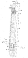
- Fig. 1 einen senkrechten Schnitt durch die Vorrichtung,
- Fig. 2 einen Ausschnitt aus Fig.1 im unteren Bereich und
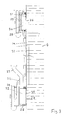
- Fig. 3 einen senkrechten Schnitt durch den linken Teil einer alternativen Vorrichtung.
- 1 is a vertical section through the device,
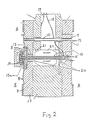
- Fig. 2 shows a detail from Fig.1 in the lower area and
- Fig. 3 is a vertical section through the left part of an alternative device.
Ein senkrechtes rohrförmiges Gehäuse 1 ist in einer nicht dargestellten Rohrleitung zwischen gesetzt, die die zu messende Flüssigkeit enthält. Im Ausführungsbeispiel fließt diese Flüssigkeit von unten nach oben und das Gehäuse 1 weist einen größeren Querschnitt auf als die Flüssigkeitsleitung, da im Gehäuse 1 eine Meßvorrichtung 2 eingesetzt ist, die den Durchflußquerschnitt des Gehäuses 1 verringert, so daß durch den größeren Querschnitt des Gehäuses 1 dafür gesorgt ist, daß der Durchflußquerschnitt des Gehäuses nicht kleiner ist als der der Rohrleitung.A vertical tubular housing 1 is interposed in a pipeline, not shown, which contains the liquid to be measured. In the exemplary embodiment, this liquid flows from bottom to top and the housing 1 has a larger cross section than the liquid line, since a
Im Gehäuse 1 ist seitlich achsparallel verlaufend ein Rohr 3 befestigt, das ringsum von er zu messenden Flüssigkeit 4 umflossen ist und dessen Durchmesser um ein Vielfaches geringer ist als der des Gehäuses 1. Im Rohr 3 befindet sich eine Referenzflüssigkeit 5, die ähnlich der zu messenden Flüssigkeit 4 ist. Ist z. B. die zu messende Flüssigkeit 4 eine Limonade, so kann die Referenzflüssigkeit von Wasser gebildet sein.In the housing 1, a
Mit dem unteren Ende mündet das Rohr 3 in einer Kammer 6, von der eine senkrechte Wand 7 in einem Ausschnitt eine senkrechte Membran 8 trägt. An der Membran liegt somit auf einer Seite die Referenzflüssigkeit 5 an. Auf der gegenüberliegenden Seite liegt an der Membran 8 eine Übertragungsflüssigkeit 9 insbesondere in Form von dünnflüssigem Öl an. Hierbei ist der rückwärtige Raum zur Membran 8 über eine Leitung 10 mit einem Raum 11 verbunden, indem sich auch die Übertragungsflüssigkeit 9 befindet. Dieser Raum 11 ist auf der Membran 8 abgewandten Seite durch eine zweite Membran 12 begrenzt, die parallel zu Membran 8 ist, so daß diese Membran parallel zur Durchflußrichtung der Flüssigkeit 4 liegt. Auf der Außenseite der Membran 12 liegt damit die Flüssigkeit 4 an, so daß auf die Außenseite der Membran 12 von der Flüssigkeit 4 einwirkende Unterschiede des hydrostatischen Druckes durch die Flüssigkeit 9 über die Leitung 10 auf die Innenseite der Membran 8 übertragen wird.With the lower end, the
Da somit die Innenseite der Membran 8 dem hydrostatischen Druck der zu messenden Flüssigkeit 4 und die Außenseite der Membran 8 dem hydrostatischen Druck der Referenzflüssigkeit 5 ausgesetzt ist, wird die Membran 8 entsprechend der Differenz dieser beiden Flüssigkeiten 4 und 5 bewegt. Hierbei ist von Bedeutung, daß der hydrostatische Druck der Referenzflüssigkeit gleichbleibend ist, da die Höhe h der Flüssigkeitssäule der Referenzflüssigkeit 5 stets gleichbleibend ist und auch das spezifische Gewicht γ 1 sich nicht ändert. Die Höhe h der Referenzflüssigkeit stellt gleichzeitig die Meßhöhe für die zu messende Flüssigkeit 4 dar. Dagegen ändert sich das spezifische Gewicht γ 2 der zu messenden Flüssigkeit 4 aufgrund ihrer unterschiedlichen Dichte. Die an der Membran 8 anliegende Druckdifferenz Δ P ist somit (h x γ ₂) - (h x γ ₁), wobei sich bei dieser Formel nur der Wert γ 2 ändert, so daß die an der Membran 8 meßbare Druckdifferenz direkt einen Wert für das spezifische Gewicht γ 2 der zu messenden Flüssigkeit und damit ihrer Dichte ergibt. Es gilt somit Δ P entspricht γ 2. Der, den hydrostatischen Drücken (h x γ ₁) und (h x γ ₂) überlagerte, um ein vielfaches höhere, Prozeßdruck wirkt in gleichem Maße auf beide Seiten der Membran 8 und hebt sich somit auf.Since the inside of the
Die von der Membran 8 ausgeführten Bewegungen werden auf eine Meßvorrichtung 11 übertragen. Diese Meßvorrichtung 11 weist ein schwingfähiges Element 13 insbesondere in Form eines schwingenden Drahtes auf, der zwischen zwei Stellen gespannt ist. Das erste Ende 13a des Drahtes 13 ist an der Membran 8 in ihrer Mitte befestigt, wobei diese Befestigungsstelle von einer Einrichtung 13a gebildet wird, die eine Überlastsicherung ist. Hierzu weist die Einrichtung 13a ein federndes Element 14 auf.The movements carried out by the
An der der Membran 8 gegenüberliegenden Seite ist das Element 13 mit seinem Ende an einem zylinderischen Teil 15 befestigt, das ein Metallrohr 16 an einem Ende verschließt. In diesem Metallrohr 16 liegt das Element 13 koaxial ein, wobei das andere der Membran 8 zugekehrte Ende des waaggerechten Metallrohrs 16 im Gehäuse 17 der unteren Meßvorrichtung 11 unverschieblich befestigt ist. Das Metallrohr 16 ist innen von einem Gas insbesondere Luft gefüllt, in dem das Element 13 schwingt. Das Element 13 ist von elektrischem Strom durchflossen und Bestandteil eines Schwingkreises, wobei eine elektrische Leitung 18 am Teil 15 und eine zweite elektrische Leitung 19 am Gehäuse 17 angeschlossen ist. Da das Metallrohr 16 und das Teil 15 gegenüber dem Gehäuse 17 durch isolierende Büchsen oder Ringe 20 gelagert ist, kann der durch die Leitung 19 angeschlossene Strom über das Gehäuse 17 das Element 13 nur über die Einrichtung 13 bzw. die Membran 8 erreichen. Das Metallrohr 16 durchquert innerhalb des Gehäuses 17 eine innere Kammer 21, in der ein Permanentmagnet 22 befestigt ist, der das Metallrohr 16 umgibt.On the side opposite the
Das drahtförmige Element 13 ist somit Bestandteil eines elektrischen Schwingkreises, wobei die Frequenz der Schwingungen des Elements 13 von seiner Spannung bestimmt wird, die wiederum durch die Zugkraft bestimmt ist, die von der Membran 8 erzeugt wird. Die Leitungen 18 und 19 führen nach außen zu einer elektrischen Einrichtung 23, die den zweiten Teil des Schwingkreises. Der Schwingkreis ist wiederum Teil eines in der elektrischen Einrichtung enthaltenen Oszillators, dessen Frequenz von der Spannung des Elements 13 abhängt. Die mechanischen Schwingungen des Elements 13 werden in ein elektrisches Wechselspannungssignal über der Induktion durch den Magneten 22 umgesetzt.The wire-shaped
Der Oszillator zeigt daher der elektrischen Einrichtung oder einer äquivalenten elektrischen Einrichtung die Frequenz des Schwingkreises an, die sich entsprechend der Dichte der zu messenden Flüssigkeit ändert. Dieses Frequenzsignal kann in elektrischen Einrichtungen verstärkt und gewandelt werden, um auf einer Skala oder einem Treibgerät Werte anzugeben, die direkt die Dichte der Flüssigkeit 4 zeigen.The oscillator therefore indicates to the electrical device or an equivalent electrical device the frequency of the resonant circuit, which changes in accordance with the density of the liquid to be measured. This frequency signal can be amplified and converted in electrical devices in order to indicate values on a scale or a driving device which directly show the density of the
Das obere Ende des Rohres 3 ist verschlossen und über eine Leitung 24 mit dem Inneren eines Balges 25 verbunden, der mit seiner Achse senkrecht und damit parallel zur Achse des Gehäuses 1 ist und innerhalb der Flüssigkeit 4 liegt. Der Balg 25 nimmt damit temperaturbedingte Volumenänderungen der Referenzflüssigkeit, hervorgerufen durch Schwankungen der Prozeßtemperatur, im Rohr 3 auf, so daß Temperaturschwankungen in gleichem Maße dem hydrostatischen Drücken (h x γ ₁) und (h x γ ₂) überlagert werden und sich nicht als Druckänderungen auf die Membran 8 auswirken. Damit ergibt sich eine vollständige temperaturkompensierte Messung der Dichte.The upper end of the
In nicht dargestellten alternativen Ausführungen kann das schwingfähige Element statt von einem Draht auch von einer Saite, einem Rohr, eine Folie oder einem federnden Element gebildet sein. Ferner kann das Element 12 mit einem Ende an der Membran 8 und mit seinem anderen Ende an der Membran 12 befestigt sein. In einer solchen Ausführung können die Übertragungsflüssigkeit 9 und die Leitung 10 fehlen.In alternative embodiments, not shown, the vibratable element can also be a string, a tube, a film or a resilient element instead of a wire be educated. Furthermore, the
Ferner ist es auch möglich, daß nur eine einzige Membran bzw. ein einziger Balg vorgesehen ist, an dem das Element 12 mit einem Ende befestigt ist, wobei dann auf der einen Seite der Membran bzw. des Balges die Referenzflüssigkeit 5 und auf der anderen Seite der Membran bzw. dem Inneren des Balges die zu messende Flüssigkeit 4 anliegt.Furthermore, it is also possible that only a single membrane or a single bellows is provided, to which the
Bei einer alternativen Ausführung kann das Gehäuse 1 in seiner Wand 1a in unterschiedlichen Höhen eine obere erste Öffnung 26 und eine darunter befindliche zweite Öffnung 27 aufweisen, in die jeweils rohrstutzenförmige Gehäuse 28 koaxial eingeschweißt sind. Die Gehäuse 28 stehen damit außen am Gehäuse 1 vor und sind jeweils durch eine Spannmutter 29 mit Sicherungskette außen verschlossen. Im oberen Gehäuse 28 liegt ein hohler kreisrunder scheibenförmiger Trägerkörper 30 ein, der durch einen Anpreßkegel oder einen Kugelabschnitt an der Innenseite der Spannmutter 29 gegen einen Innenflansch des Gehäuses 28 abdichtend gedrückt wird.In an alternative embodiment, the housing 1 can have an upper
Die Innenseite des Körpers 30 bei der ersten Öffnung 26 bildet eine Membran 31, an deren Außenseite die zu messende Flüssigkeit anliegt. Im Innern des Körpers 30 befindet sich die Referenzflüssigkeit, die über eine Leitung 31 mit dem hohlen Trägerkörper 32 der zweiten Öffnung 27 verbunden ist. Dieser Körper 32 enthält nicht nur auf der der zu messenden Flüssigkeit 4 zugewandten Seite eine Membran, sondern innen darüber hinaus den Differenzdrucksensor mit Schwingseite einschließlich einer zweiten Membran oder einem zweiten Balg entsprechend dem ersten Ausführungsbeispiel. Deshalb ist auch am Körper 32 ein elektrischer Anschluß 33 zur elektrischen Einrichtung 23 vorgesehen. Die Arbeitsweise dieses zweiten Ausführungsbeispiels entspricht der Arbeitsweise des ersten Ausführungsbeispiels. Hierbei übernimmt die obere Membran 31 die Funktion des Balgs 25 beim ersten Ausführungsbeispiel und die untere Membran 34 die Arbeitsweise der Membran 12. Das Innere des Körpers 32 ist nicht dargestellt und entspricht der Ausführung nach Fig. 2.The inside of the
Claims (19)
Applications Claiming Priority (2)
| Application Number | Priority Date | Filing Date | Title |
|---|---|---|---|
| DE3616385 | 1986-05-15 | ||
| DE19863616385 DE3616385A1 (en) | 1986-05-15 | 1986-05-15 | METHOD AND DEVICE FOR MEASURING THE DENSITY OF A LIQUID |
Publications (2)
| Publication Number | Publication Date |
|---|---|
| EP0245673A2 true EP0245673A2 (en) | 1987-11-19 |
| EP0245673A3 EP0245673A3 (en) | 1988-07-20 |
Family
ID=6300897
Family Applications (1)
| Application Number | Title | Priority Date | Filing Date |
|---|---|---|---|
| EP87105799A Withdrawn EP0245673A3 (en) | 1986-05-15 | 1987-04-18 | Method and apparatus for measuring the density of a liquid |
Country Status (3)
| Country | Link |
|---|---|
| EP (1) | EP0245673A3 (en) |
| CN (1) | CN87103492A (en) |
| DE (1) | DE3616385A1 (en) |
Families Citing this family (1)
| Publication number | Priority date | Publication date | Assignee | Title |
|---|---|---|---|---|
| ES2907457T3 (en) | 2011-09-01 | 2022-04-25 | Microtech Medical Technologies Ltd | Implantable sensor device for measuring a fluid pressure |
Citations (6)
| Publication number | Priority date | Publication date | Assignee | Title |
|---|---|---|---|---|
| SU177142A1 (en) * | Государственный институт проектированию , научно исследовательским работам нефтедобывающей промышленности | HYDROSTATIC FLUID DIMENSIONS WITH AUTOMATIC TEMPERATURE COMPENSATION | ||
| US3046789A (en) * | 1957-05-20 | 1962-07-31 | Borg Warner | Differential pressure transducer |
| DE1498317A1 (en) * | 1965-05-15 | 1969-10-16 | Eckardt Ag J | Method and device for force or pressure measurement |
| US3589200A (en) * | 1967-09-26 | 1971-06-29 | Alfa Laval Ab | Apparatus for measuring the density of liquids |
| DE2903740A1 (en) * | 1978-02-03 | 1979-08-23 | Yamatake Honeywell Co Ltd | Densimeter using two measurement positions - determines pressure difference in fluid at two points in duct with small cross=section on upstream side |
| US4198867A (en) * | 1977-09-19 | 1980-04-22 | The Foxboro Company | Temperature compensating means for pressure measuring apparatus |
Family Cites Families (2)
| Publication number | Priority date | Publication date | Assignee | Title |
|---|---|---|---|---|
| SU177142A (en) * | ||||
| DE2402986A1 (en) * | 1974-01-23 | 1975-12-11 | Franz Xaver Dr Ing Gschwind | Liquid density transducer - measures axial displacement of diaphragm in two-part shell with reference liquid and two membranes |
-
1986
- 1986-05-15 DE DE19863616385 patent/DE3616385A1/en not_active Withdrawn
-
1987
- 1987-04-18 EP EP87105799A patent/EP0245673A3/en not_active Withdrawn
- 1987-05-14 CN CN198787103492A patent/CN87103492A/en active Pending
Patent Citations (6)
| Publication number | Priority date | Publication date | Assignee | Title |
|---|---|---|---|---|
| SU177142A1 (en) * | Государственный институт проектированию , научно исследовательским работам нефтедобывающей промышленности | HYDROSTATIC FLUID DIMENSIONS WITH AUTOMATIC TEMPERATURE COMPENSATION | ||
| US3046789A (en) * | 1957-05-20 | 1962-07-31 | Borg Warner | Differential pressure transducer |
| DE1498317A1 (en) * | 1965-05-15 | 1969-10-16 | Eckardt Ag J | Method and device for force or pressure measurement |
| US3589200A (en) * | 1967-09-26 | 1971-06-29 | Alfa Laval Ab | Apparatus for measuring the density of liquids |
| US4198867A (en) * | 1977-09-19 | 1980-04-22 | The Foxboro Company | Temperature compensating means for pressure measuring apparatus |
| DE2903740A1 (en) * | 1978-02-03 | 1979-08-23 | Yamatake Honeywell Co Ltd | Densimeter using two measurement positions - determines pressure difference in fluid at two points in duct with small cross=section on upstream side |
Non-Patent Citations (1)
| Title |
|---|
| AUTOMATISIERUNGSTECHNISCHE PRAXIS ATP, Band 27, Nr. 1, Januar 1985, Seiten 6-16, M}nchen, DE; G. STROHRMANN: "atp-Marktanalyse: Messumformer f}r Druck und Druckdifferenz" * |
Also Published As
| Publication number | Publication date |
|---|---|
| DE3616385A1 (en) | 1987-11-19 |
| EP0245673A3 (en) | 1988-07-20 |
| CN87103492A (en) | 1987-12-02 |
Similar Documents
| Publication | Publication Date | Title |
|---|---|---|
| DE69032658T2 (en) | IMPROVED STABILITY IN A CORIOLIS MASS FLOW METER | |
| DE3782944T2 (en) | FERROMAGNETIC DRIVES AND SPEED CONVERTERS FOR A CORIOLIS MASS FLOW METER. | |
| DE3877913T2 (en) | VIBRATION RHEOMETER. | |
| EP1253409A1 (en) | Magnetic circuit arrangement for a measuring transducer | |
| EP3415875A1 (en) | Magnetic-inductive flow measuring device and method for operating a magnetic-inductive flow measuring device | |
| DE2008541C3 (en) | Method for determining the mass of material contained in a flow medium and device for carrying out the method | |
| DE102020111127A1 (en) | Method of monitoring a Coriolis mass flow sensor | |
| DE19537880A1 (en) | Mass flow meter for measuring mass flow rate of fluid | |
| EP0195938B1 (en) | Yarn tension measuring device using an elastic yarn-guiding element | |
| DE4026724A1 (en) | Mass flowmeter with replaceable vibration tube - coupled via ranges to connection tubes rigidly attached to housing at least partially enclosing vibration tube | |
| DE69409631T2 (en) | Liquid detector | |
| EP0401524B1 (en) | Pressure sensor for infusion conduits | |
| DE69117767T2 (en) | METHOD AND DEVICE FOR DETERMINING THE PART OF PARAMAGNETIC COMPONENTS IN GAS MIXTURES | |
| DE2460703B2 (en) | Apparatus for measuring the density of a dirty fluid J. Agar Instrumentation Ltd, Alres- | |
| WO2011079999A2 (en) | Device for determining at least one process variable | |
| EP0245673A2 (en) | Method and apparatus for measuring the density of a liquid | |
| DE69022936T2 (en) | Accelerometer and accelerometer system. | |
| DE3411156A1 (en) | Float flow meter | |
| DE2822943A1 (en) | Probe which measures electrical conductivity of liq. - uses coils to generate and detect induced voltage in liq. | |
| DE102019134608A1 (en) | Sensor of a measuring device | |
| DE2209260C3 (en) | Level limit display | |
| DE4417332C2 (en) | Mass flow meter | |
| DE1498602B2 (en) | DEVICE FOR CONTINUOUS DETERMINATION OF THE WEIGHT OF FLOWABLE MATERIALS | |
| DE3933627A1 (en) | Sensor with permanent magnet system for measuring motion - has permanent magnet rings separated by weakly magnetic ring plate, coil arrangement | |
| AT409551B (en) | Viscosity decision procedure for density measurement, involves taking peak point of vibration of oscillating type density meter as reference point |
Legal Events
| Date | Code | Title | Description |
|---|---|---|---|
| PUAI | Public reference made under article 153(3) epc to a published international application that has entered the european phase |
Free format text: ORIGINAL CODE: 0009012 |
|
| AK | Designated contracting states |
Kind code of ref document: A2 Designated state(s): AT BE CH DE ES FR GB GR IT LI NL SE |
|
| PUAL | Search report despatched |
Free format text: ORIGINAL CODE: 0009013 |
|
| AK | Designated contracting states |
Kind code of ref document: A3 Designated state(s): AT BE CH DE ES FR GB GR IT LI NL SE |
|
| 17P | Request for examination filed |
Effective date: 19890114 |
|
| 17Q | First examination report despatched |
Effective date: 19901219 |
|
| RAP3 | Party data changed (applicant data changed or rights of an application transferred) |
Owner name: WALTER SCHROER MESS- UND REGELTECHNIK |
|
| STAA | Information on the status of an ep patent application or granted ep patent |
Free format text: STATUS: THE APPLICATION IS DEEMED TO BE WITHDRAWN |
|
| 18D | Application deemed to be withdrawn |
Effective date: 19910702 |
|
| RIN1 | Information on inventor provided before grant (corrected) |
Inventor name: KRUEGER, KLAUS |