EP0244710B1 - Decke für einen Glasschmelzofen oder eine Arbeitswanne - Google Patents
Decke für einen Glasschmelzofen oder eine Arbeitswanne Download PDFInfo
- Publication number
- EP0244710B1 EP0244710B1 EP87106005A EP87106005A EP0244710B1 EP 0244710 B1 EP0244710 B1 EP 0244710B1 EP 87106005 A EP87106005 A EP 87106005A EP 87106005 A EP87106005 A EP 87106005A EP 0244710 B1 EP0244710 B1 EP 0244710B1
- Authority
- EP
- European Patent Office
- Prior art keywords
- roof
- roof according
- horizontal
- constructed
- cover plates
- Prior art date
- Legal status (The legal status is an assumption and is not a legal conclusion. Google has not performed a legal analysis and makes no representation as to the accuracy of the status listed.)
- Expired - Lifetime
Links
- 238000002844 melting Methods 0.000 title claims abstract description 17
- 230000008018 melting Effects 0.000 title claims abstract description 17
- 239000011521 glass Substances 0.000 title claims abstract description 14
- 239000004575 stone Substances 0.000 claims description 15
- 239000000155 melt Substances 0.000 claims description 12
- 239000011819 refractory material Substances 0.000 claims description 10
- 230000000284 resting effect Effects 0.000 claims description 3
- 238000007670 refining Methods 0.000 claims description 2
- XEEYBQQBJWHFJM-UHFFFAOYSA-N Iron Chemical compound [Fe] XEEYBQQBJWHFJM-UHFFFAOYSA-N 0.000 claims 4
- 229910052742 iron Inorganic materials 0.000 claims 2
- 230000005855 radiation Effects 0.000 abstract description 14
- 239000000463 material Substances 0.000 abstract description 6
- 239000006060 molten glass Substances 0.000 abstract description 4
- 238000010276 construction Methods 0.000 description 18
- 239000000156 glass melt Substances 0.000 description 14
- 238000013461 design Methods 0.000 description 11
- 238000005496 tempering Methods 0.000 description 7
- 238000001816 cooling Methods 0.000 description 6
- 238000010438 heat treatment Methods 0.000 description 6
- 238000004519 manufacturing process Methods 0.000 description 5
- VYPSYNLAJGMNEJ-UHFFFAOYSA-N Silicium dioxide Chemical compound O=[Si]=O VYPSYNLAJGMNEJ-UHFFFAOYSA-N 0.000 description 4
- 238000011960 computer-aided design Methods 0.000 description 4
- 230000008439 repair process Effects 0.000 description 4
- 238000007689 inspection Methods 0.000 description 3
- 238000010521 absorption reaction Methods 0.000 description 2
- 238000006073 displacement reaction Methods 0.000 description 2
- 238000003825 pressing Methods 0.000 description 2
- 239000000377 silicon dioxide Substances 0.000 description 2
- 238000003756 stirring Methods 0.000 description 2
- PNEYBMLMFCGWSK-UHFFFAOYSA-N aluminium oxide Inorganic materials [O-2].[O-2].[O-2].[Al+3].[Al+3] PNEYBMLMFCGWSK-UHFFFAOYSA-N 0.000 description 1
- 230000000712 assembly Effects 0.000 description 1
- 238000000429 assembly Methods 0.000 description 1
- 238000009529 body temperature measurement Methods 0.000 description 1
- 239000011449 brick Substances 0.000 description 1
- 229910010293 ceramic material Inorganic materials 0.000 description 1
- 238000002485 combustion reaction Methods 0.000 description 1
- 239000004035 construction material Substances 0.000 description 1
- 238000004090 dissolution Methods 0.000 description 1
- 238000000265 homogenisation Methods 0.000 description 1
- 238000009434 installation Methods 0.000 description 1
- 238000000034 method Methods 0.000 description 1
- 238000012544 monitoring process Methods 0.000 description 1
- 239000002245 particle Substances 0.000 description 1
- 238000009417 prefabrication Methods 0.000 description 1
- 230000000717 retained effect Effects 0.000 description 1
- 229910052851 sillimanite Inorganic materials 0.000 description 1
- 238000003860 storage Methods 0.000 description 1
Images


Classifications
-
- C—CHEMISTRY; METALLURGY
- C03—GLASS; MINERAL OR SLAG WOOL
- C03B—MANUFACTURE, SHAPING, OR SUPPLEMENTARY PROCESSES
- C03B5/00—Melting in furnaces; Furnaces so far as specially adapted for glass manufacture
- C03B5/04—Melting in furnaces; Furnaces so far as specially adapted for glass manufacture in tank furnaces
Definitions
- the invention relates to a blanket for a glass melting furnace or a work tub, a refining part or the like.
- a glass melting furnace (basin) made of refractory material, the blanket spanning the work tub at intervals, supporting the load of the blanket, and supporting the free spaces between the support elements , horizontal cover plates inserted transversely between the support elements.
- these Areits troughs are designed in any shape and usually have an undivided combustion chamber, a distance between the glass bath surface and the vault of more than 50 cm and can usually only be temperature-controlled overall.
- the installation of stirrers or thermocouples is very difficult due to the large distance from the glass bath to the vault.
- the construction of the upper furnace is very complex, since the vault can only be made from relatively small-sized stones.
- the invention has for its object a work pan and feeder of a glass melting furnace with a glass melt in the flow, covered by a radiation blanket made of highly heat-resistant furnace building block material containing basin with at least one feeder arranged on it in a substantially improved design, in order to be able to continuously control and influence and adjust the required and intended state parameters of the glass melt on the flow paths from the melting tank through the working tank to the feeders.
- a radiation blanket made of highly heat-resistant furnace building block material containing basin with at least one feeder arranged on it in a substantially improved design, in order to be able to continuously control and influence and adjust the required and intended state parameters of the glass melt on the flow paths from the melting tank through the working tank to the feeders.
- the design of the work tub and in particular the radiation ceiling should be uncomplicated, allow control access to the glass melt at various points without difficulty and make it possible to use means for influencing the temperature.
- the log arches are created as transportable units that do not have to have any settings during tempering, which are still easy to repair, whereby there are no structural parts above the superstructure of a furnace or furnace part that require the introduction of cooling elements, heating elements, temperature measuring elements or Impede stirrers and the like and which enables the operator of a furnace to carry out the repair independently.
- the load of the ceiling is not absorbed by a closed vault, but that for this purpose the work trough has horizontal support elements spanning the load of the ceiling at intervals, the free distances between the support elements covering horizontal cover plates inserted transversely between the support elements are present, which enables a very uncomplicated accessibility of the surface of the glass melt from above the ceiling.
- a very advantageous and economical construction of the ceiling is achieved in that the individual stones used both for the support elements and for the cover plates, depending on their shape or dimension, as modules of a collective or a family of stone building elements are trained.
- a preferred embodiment provides that the ceiling components joined together to form the ceiling of the work tub in modular construction, avoiding an arching of the ceiling, are arranged horizontally in each case forming a flat ceiling with a clear vertical distance from the surface of the melt between 75 mm and 700 mm.
- the support elements are designed and arranged as a right-angled, straight arches on the walls of the basin forming the tub.
- This design of the support elements as straight arches forms the basic requirement for the archless flat ceiling at a comparatively short distance between 150 and 500 mm from the surface of the melt.
- coverable openings at different points above the working trough enable an uncomplicated control of the state parameters of the glass melt on their flow paths from the melting furnace to the feeders as well as the use of state-influencing means for local heating or cooling, generation of stirring movement or control of the melt flow and the like.
- Another advantage of the invention is that it can be used for any shape of tub, so that, for example in a furnace repair, without changing the floor plan and without any significant change in the existing tub anchorage, the flat ceiling can be applied.
- upright beams can be arranged between the log arches as a transportable and independent element as an intermediate support between the log arches.
- Bendable arches of the conventional type have the disadvantage that they have a tendency to migrate under load have upwards
- the means according to the invention also have the task of keeping the arches vertically in alignment and at the same time to keep the escape laterally.
- the invention thus makes it possible for the first time to use right-angled arches on a decisive scale as a construction element, since they can be manufactured as transport units, so that there is no need to manufacture them on the construction site and constant monitoring during tempering is no longer necessary, but at the same time permanent functionality is guaranteed.
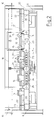
- the inventive design of the blanket 1 consists in that this is formed with the work tub 2 at intervals A, B, C, the load of the ceiling 1 receiving horizontal support elements 3 and the free distances A, B, C between the support elements 3 overlapping, inserted between the support elements 3 horizontal cover plates 4 .
- a load-bearing, flat radiation ceiling can be produced in a comparatively light construction.
- This ceiling system is particularly suitable for the fact that the individual stones used both for the support elements 3 and for the cover plates 4 are designed as modules of a collective or a family of stone building elements, depending on their shape or dimension.
- This construction with components designed or assembled as modules gives a further advantage, as previously mentioned, the possibility of carrying out the construction as a computer aided design (CAD), which results in considerable advantages in terms of design effort, time required for construction and Calculation, as well as reduction of manufacturing costs by using typed or modulated individual elements.
- CAD computer aided design
- the ceiling components 3, 4 joined together to form the ceiling 1 of the work tub 2 in a modular construction form a flat ceiling with a clear vertical distance of the surface 5 of the melt 29 is arranged between 75 mm and 700 mm.
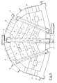
- the support elements 3 are each formed and arranged as perpendicular, straight arches resting on the walls 6 of the basin 7 forming the tub 2.
- the arches 3, which are perpendicular, are given their free carrying capacity by being clamped under lateral, horizontal support tension between lateral abutments 8, 8 'on the support supports 9, 9' of the furnace frame 10.
- the abutments 8, 8 ′ have means 11 for adjusting the horizontal abutment tension, preferably clamping screws, as is shown purely symbolically by arrows in FIGS. 4 and 5.
- cover plates 4 With the configuration of the radiation ceiling above the working trough according to the invention, a particularly effective and thus essential design of the cover plates 4 results from the fact that they cover the guide areas 13, 13 'of the perpendicular arches 3 in to the longitudinal axis the arches are displaceable in the parallel direction (FIG. 1) and in particular in that cover plates 4 are formed with coverable openings 14.
- these openings 14 can be distributed in large numbers practically over the entire area of the radiation ceiling. They thus give you the opportunity, on the one hand, to set partial temperature drops in the melt through released openings as a result of radiation, to measure state parameters of the melt such as temperature and viscosity with the introduction of suitable measuring instruments, or by introducing known heating or cooling elements to the state of the melt in the run to be able to influence the work tub significantly and in a targeted manner.
- a further advantage results from the fact that stirrers can also be used locally, which contribute to the homogenization of the melt mass by generating a local convection system with bath circulation. Such a stirrer is shown purely by way of example in FIG. 5.
- cover plates 4, as shown in FIG. 2 are displaceably held by mobile holding devices 15.
- a holding device can, for example, as shown purely schematically, have movable tongs which can be moved in a hanging rail track 32 by means of a known lifting device.
- one or the other cover plate 4 can be temporarily removed from its storage and set aside.
- a horizontal one is erected above the flat ceiling 1 on the side furnace frame 10 the flat ceiling spanning work and inspection stage 16 is arranged.
- the stage in cooperation with the main features of the flat radiation ceiling and because of the uncomplicated accessibility of the melt surface 5 through the openings 14, is very advantageous and uncomplicated for use with measuring devices 17 for example for measuring the temperature and / or viscosity of the glass melt 18 and of heating or cooling elements 19, stirrers 20 and / or similar means for influencing and / or checking the state parameters of the glass melt.
- measuring devices 17 for example for measuring the temperature and / or viscosity of the glass melt 18 and of heating or cooling elements 19, stirrers 20 and / or similar means for influencing and / or checking the state parameters of the glass melt.
- stirrers 20 stirrers 20 and / or similar means for influencing and / or checking the state parameters of the glass melt.
- the cover plates 4 are preferably made of high-alumina refractory material such as sillimanite. Furthermore, as shown in FIG. 1, these cover plates 4 'are formed with broken, in particular beveled, rounded or chamfered edge regions 26. This successfully avoids the risk of flaking of stone particles in the area of these edges, which could contaminate the molten glass bath.
- the stone elements 23 of the arches 23 made of refractory material with right angles very high silica content like silica material are made.
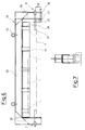
- the invention also consists in the fact that a log sheet 3 made of stones made of refractory material, as has long been known, is not only designed as a transport unit by means of a frame 32, but also avoids the previous disadvantages, while of tempering and during operation require special attention.
- the right-angled arch 3 is held by a frame 32 consisting of a cross member 35 and side webs 36 directed downwards on both sides, which frame 43 can compensate for length extensions during the tempering by means of spring assemblies.
- the springs 43 which can be designed, for example, as plate springs, are arranged in a hollow cylinder 40 and are pretensioned by a pressure plate 42, which is held in position by means of a screw bolt 41.
- the force of the spring assembly 43 acts on a pressure plate 33, which bears against the end faces of the bend 3.
- the expansion of the springs ensures during tempering that both the holding force of the sheet 3 is retained, and on the other hand the expansion but can be included.
- the pressure plates 33 are fixed by means of screw bolts 39 after the tempering, the clearance of which is dimensioned such that they can move freely in the pressing direction, so that they can move freely a temperature reduction does not hinder the displacement of the pressure plate 33 by the spring assembly 43.
- the clamping screw 47 resting on the side webs 36 presses the bolt 39 against the refractory material of the arch 3 without the other end of the bolt 39 hindering a displacement to maintain the tension of the arch 3.
- the upper cross member 35 has hot eyes 34 and the sheet is held by means of retaining bolts 38 which penetrate holes 37 in refractory material and are held by the lateral webs 36.
- U-shaped profiles 44 are attached to the crossmember, which engage the refractory bricks via insulating chamotte 46. Since they rest on the top of the stones, it is ensured that the stones cannot migrate upwards under pressure. This creates the bendable arch as a controllable, predictable and transportable component that makes it possible to create a cover directly over the surface of the glass melt. By creating openings special cooling z. B. before the feeder, but it can also, as mentioned above, elements for additional heating, temperature measurement, stirring and the like can be used.
Landscapes
- Chemical & Material Sciences (AREA)
- Engineering & Computer Science (AREA)
- Materials Engineering (AREA)
- Organic Chemistry (AREA)
- Glass Melting And Manufacturing (AREA)
- Furnace Housings, Linings, Walls, And Ceilings (AREA)
- Glass Compositions (AREA)
- Filling Or Discharging Of Gas Storage Vessels (AREA)
Applications Claiming Priority (5)
| Application Number | Priority Date | Filing Date | Title |
|---|---|---|---|
| DE3615276 | 1986-05-06 | ||
| DE19863615276 DE3615276A1 (de) | 1986-05-06 | 1986-05-06 | Arbeitswanne eines glasschmelzofens |
| DE19873711045 DE3711045A1 (de) | 1986-05-06 | 1987-04-06 | Decke fuer einen glasschmelzofen oder eine arbeitswanne |
| DE3711045 | 1987-04-06 | ||
| CA000558537A CA1330164C (en) | 1986-05-06 | 1988-02-05 | Roof for working area, melting area or gob feeder of a glass melting furnace |
Publications (3)
| Publication Number | Publication Date |
|---|---|
| EP0244710A2 EP0244710A2 (de) | 1987-11-11 |
| EP0244710A3 EP0244710A3 (en) | 1989-08-02 |
| EP0244710B1 true EP0244710B1 (de) | 1992-01-29 |
Family
ID=27167873
Family Applications (1)
| Application Number | Title | Priority Date | Filing Date |
|---|---|---|---|
| EP87106005A Expired - Lifetime EP0244710B1 (de) | 1986-05-06 | 1987-04-24 | Decke für einen Glasschmelzofen oder eine Arbeitswanne |
Country Status (6)
| Country | Link |
|---|---|
| US (1) | US4836841A (es) |
| EP (1) | EP0244710B1 (es) |
| AT (1) | ATE72211T1 (es) |
| CA (1) | CA1330164C (es) |
| DE (3) | DE3615276A1 (es) |
| ES (1) | ES2029807T3 (es) |
Families Citing this family (5)
| Publication number | Priority date | Publication date | Assignee | Title |
|---|---|---|---|---|
| US5007950A (en) * | 1989-12-22 | 1991-04-16 | Ppg Industries, Inc. | Compressed, wedged float glass bottom structure |
| US20160238279A1 (en) * | 2015-02-13 | 2016-08-18 | Corning Incorporated | Methods of processing a furnace |
| EP3431447B1 (en) * | 2017-07-21 | 2020-03-04 | Engie | A method of melting raw materials such as glass by a cross-fired melting furnace |
| CN107576200A (zh) * | 2017-09-21 | 2018-01-12 | 贵州航天新力铸锻有限责任公司 | 台车式加热炉的炉底板的放置方法 |
| KR102415723B1 (ko) * | 2017-11-20 | 2022-07-04 | 코닝 인코포레이티드 | 용탕 교반 시스템 및 용탕 교반 방법 |
Family Cites Families (15)
| Publication number | Priority date | Publication date | Assignee | Title |
|---|---|---|---|---|
| US1339615A (en) * | 1916-12-14 | 1920-05-11 | Wundrack Otto | Flat arch for furnaces |
| US1949380A (en) * | 1929-11-05 | 1934-02-27 | Owens Illinois Glass Co | Glass furnace |
| DE639573C (de) * | 1933-11-15 | 1936-12-08 | Josef Watzula | Glasschmelzofen |
| US2773111A (en) * | 1948-01-23 | 1956-12-04 | Saint Gobain | Method and apparatus for manufacturing glass |
| US2834306A (en) * | 1952-02-26 | 1958-05-13 | Pilkington Brothers Ltd | Furnaces |
| DE1015976B (de) * | 1956-02-09 | 1957-09-19 | Bbc Brown Boveri & Cie | Haengedecke fuer Industrieoefen, Kuehlkammern od. dgl. mit grossen Abmessungen |
| DE1130116B (de) * | 1959-06-26 | 1962-05-24 | Georges Henry | Vorrichtung zur Regelung des Betriebes von Glasschmelz-Wannenoefen |
| US3134199A (en) * | 1960-05-19 | 1964-05-26 | North American Refractories | Complexed refractory brick |
| US3248203A (en) * | 1961-10-30 | 1966-04-26 | Owens Corning Fiberglass Corp | Apparatus for heat control of forehearths |
| FR1317242A (fr) * | 1961-11-27 | 1963-02-08 | Glaces De Boussois | Perfectionnements aux installations pour la fabrication du verre plat |
| US3201219A (en) * | 1962-06-01 | 1965-08-17 | Frazier Simplex | Glass melting furnace |
| DE2203944A1 (de) * | 1972-01-28 | 1973-08-02 | Schulte Fa D W | Bauverband feuerfester bausteine fuer haengedecken |
| IT8322362U1 (it) * | 1983-07-14 | 1985-01-14 | S I T I Soc Impianti Termoelettrici Industriali S P A | Strutture di sostegno per volte di Forni |
| US4622059A (en) * | 1985-10-08 | 1986-11-11 | Emhart Industries, Inc. | Apparatus for controlling temperature within a forehearth |
| US4704155A (en) * | 1986-06-11 | 1987-11-03 | Ppg Industries, Inc. | Heating vessel lid construction for a glass melting furnace |
-
1986
- 1986-05-06 DE DE19863615276 patent/DE3615276A1/de active Granted
-
1987
- 1987-04-06 DE DE19873711045 patent/DE3711045A1/de not_active Withdrawn
- 1987-04-24 DE DE8787106005T patent/DE3776397D1/de not_active Expired - Fee Related
- 1987-04-24 ES ES198787106005T patent/ES2029807T3/es not_active Expired - Lifetime
- 1987-04-24 EP EP87106005A patent/EP0244710B1/de not_active Expired - Lifetime
- 1987-04-24 AT AT87106005T patent/ATE72211T1/de not_active IP Right Cessation
- 1987-04-29 US US07/043,872 patent/US4836841A/en not_active Expired - Lifetime
-
1988
- 1988-02-05 CA CA000558537A patent/CA1330164C/en not_active Expired - Fee Related
Also Published As
| Publication number | Publication date |
|---|---|
| DE3776397D1 (de) | 1992-03-12 |
| ATE72211T1 (de) | 1992-02-15 |
| US4836841A (en) | 1989-06-06 |
| ES2029807T3 (es) | 1992-10-01 |
| DE3615276C2 (es) | 1988-03-10 |
| EP0244710A2 (de) | 1987-11-11 |
| CA1330164C (en) | 1994-06-14 |
| DE3615276A1 (de) | 1987-11-19 |
| EP0244710A3 (en) | 1989-08-02 |
| DE3711045A1 (de) | 1988-10-27 |
Similar Documents
| Publication | Publication Date | Title |
|---|---|---|
| DE2203360A1 (de) | Ofenwagen | |
| EP0232842B1 (de) | Elementkonstruktion, insbesondere Wand- und/oder Deckenkonstruktion | |
| EP0067451B1 (de) | Tunnelofenwagen | |
| EP3355015B1 (de) | Tragelement für einen tunnelofenwagen oder -schlitten, tunnelofenwagen oder -schlitten mit derartigen tragelementen sowie tunnelofen mit einem derartigen tunnelofenwagen oder -schlitten | |
| EP0244710B1 (de) | Decke für einen Glasschmelzofen oder eine Arbeitswanne | |
| DE3839346C1 (es) | ||
| DE1433463A1 (de) | Gewoelbte Ofendecke | |
| DE3739452C1 (de) | Koksofentuer mit keramischem Schildaufbau | |
| DE3832358C2 (es) | ||
| DE4039601C2 (es) | ||
| DE2838024A1 (de) | Abfallvorerhitzer | |
| DE3128655A1 (de) | "ofen fuer die waermebehandlung von glasscheiben" | |
| EP3296476A1 (de) | Anordnung zum verbinden einer gebäudewand mit einer boden- oder deckenplatte und formbaustein für eine solche anordnung | |
| DE2325529B1 (de) | Hängedecke für Industrieöfen | |
| DE2540401B2 (de) | Feuerfest in Sandwichbauweise zugestellter Tunnelofen | |
| DE3328870A1 (de) | Ofenwagen fuer brennoefen | |
| DE2455296C3 (de) | Wand mit Stützen und daran befestigten Wandplatten | |
| DE4301841C2 (de) | Periodischer Ofen | |
| DE2923612A1 (de) | Waermebehandlungsofen | |
| DE3807243C1 (en) | Suspension device for gas-permeable partition walls | |
| DE2722529A1 (de) | Traggeruest bzw. -gestell fuer keramisches gut | |
| EP0545018B1 (de) | Kanal für die Temperatureinstellung eines Stromes schmelzbarer Materialien | |
| DE877442C (de) | Bedienungsbuehne fuer Koksofenbatterien | |
| EP2187156B1 (de) | Hängedeckensystem für Innenauskleidung von Öfen | |
| DE10000276A1 (de) | Tragende Struktur für Brennöfen mit sehr hoher Brenntemperatur |
Legal Events
| Date | Code | Title | Description |
|---|---|---|---|
| PUAI | Public reference made under article 153(3) epc to a published international application that has entered the european phase |
Free format text: ORIGINAL CODE: 0009012 |
|
| AK | Designated contracting states |
Kind code of ref document: A2 Designated state(s): AT BE CH DE ES FR GB IT LI NL SE |
|
| PUAL | Search report despatched |
Free format text: ORIGINAL CODE: 0009013 |
|
| AK | Designated contracting states |
Kind code of ref document: A3 Designated state(s): AT BE CH DE ES FR GB IT LI NL SE |
|
| 17P | Request for examination filed |
Effective date: 19890914 |
|
| RAP1 | Party data changed (applicant data changed or rights of an application transferred) |
Owner name: BETEILIGUNGEN SORG GMBH & CO. KG |
|
| 17Q | First examination report despatched |
Effective date: 19900720 |
|
| RAP1 | Party data changed (applicant data changed or rights of an application transferred) |
Owner name: BETEILIGUNGEN SORG GMBH & CO. KG |
|
| GRAA | (expected) grant |
Free format text: ORIGINAL CODE: 0009210 |
|
| AK | Designated contracting states |
Kind code of ref document: B1 Designated state(s): AT BE CH DE ES FR GB IT LI NL SE |
|
| REF | Corresponds to: |
Ref document number: 72211 Country of ref document: AT Date of ref document: 19920215 Kind code of ref document: T |
|
| ITF | It: translation for a ep patent filed | ||
| ET | Fr: translation filed | ||
| GBT | Gb: translation of ep patent filed (gb section 77(6)(a)/1977) | ||
| REF | Corresponds to: |
Ref document number: 3776397 Country of ref document: DE Date of ref document: 19920312 |
|
| PLBI | Opposition filed |
Free format text: ORIGINAL CODE: 0009260 |
|
| REG | Reference to a national code |
Ref country code: ES Ref legal event code: FG2A Ref document number: 2029807 Country of ref document: ES Kind code of ref document: T3 |
|
| 26 | Opposition filed |
Opponent name: FIRMA HERMANN HEYE Effective date: 19920912 |
|
| NLR1 | Nl: opposition has been filed with the epo |
Opponent name: FIRMA HERMANN HEYE. |
|
| PLBN | Opposition rejected |
Free format text: ORIGINAL CODE: 0009273 |
|
| STAA | Information on the status of an ep patent application or granted ep patent |
Free format text: STATUS: OPPOSITION REJECTED |
|
| 27O | Opposition rejected |
Effective date: 19930321 |
|
| NLR2 | Nl: decision of opposition | ||
| EAL | Se: european patent in force in sweden |
Ref document number: 87106005.9 |
|
| PGFP | Annual fee paid to national office [announced via postgrant information from national office to epo] |
Ref country code: CH Payment date: 19970325 Year of fee payment: 11 |
|
| PGFP | Annual fee paid to national office [announced via postgrant information from national office to epo] |
Ref country code: SE Payment date: 19970327 Year of fee payment: 11 |
|
| PGFP | Annual fee paid to national office [announced via postgrant information from national office to epo] |
Ref country code: BE Payment date: 19980319 Year of fee payment: 12 |
|
| PG25 | Lapsed in a contracting state [announced via postgrant information from national office to epo] |
Ref country code: SE Free format text: LAPSE BECAUSE OF NON-PAYMENT OF DUE FEES Effective date: 19980425 |
|
| PG25 | Lapsed in a contracting state [announced via postgrant information from national office to epo] |
Ref country code: LI Free format text: LAPSE BECAUSE OF NON-PAYMENT OF DUE FEES Effective date: 19980430 Ref country code: CH Free format text: LAPSE BECAUSE OF NON-PAYMENT OF DUE FEES Effective date: 19980430 |
|
| PGFP | Annual fee paid to national office [announced via postgrant information from national office to epo] |
Ref country code: NL Payment date: 19980430 Year of fee payment: 12 |
|
| REG | Reference to a national code |
Ref country code: CH Ref legal event code: PL |
|
| EUG | Se: european patent has lapsed |
Ref document number: 87106005.9 |
|
| PG25 | Lapsed in a contracting state [announced via postgrant information from national office to epo] |
Ref country code: BE Free format text: LAPSE BECAUSE OF NON-PAYMENT OF DUE FEES Effective date: 19990430 |
|
| BERE | Be: lapsed |
Owner name: BETEILIGUNGEN SORG G.M.B.H. & CO. K.G. Effective date: 19990430 |
|
| PG25 | Lapsed in a contracting state [announced via postgrant information from national office to epo] |
Ref country code: NL Free format text: LAPSE BECAUSE OF NON-PAYMENT OF DUE FEES Effective date: 19991101 |
|
| NLV4 | Nl: lapsed or anulled due to non-payment of the annual fee |
Effective date: 19991101 |
|
| PGFP | Annual fee paid to national office [announced via postgrant information from national office to epo] |
Ref country code: FR Payment date: 20000321 Year of fee payment: 14 Ref country code: DE Payment date: 20000321 Year of fee payment: 14 |
|
| PGFP | Annual fee paid to national office [announced via postgrant information from national office to epo] |
Ref country code: ES Payment date: 20000407 Year of fee payment: 14 |
|
| PGFP | Annual fee paid to national office [announced via postgrant information from national office to epo] |
Ref country code: AT Payment date: 20000412 Year of fee payment: 14 |
|
| PGFP | Annual fee paid to national office [announced via postgrant information from national office to epo] |
Ref country code: GB Payment date: 20000419 Year of fee payment: 14 |
|
| PG25 | Lapsed in a contracting state [announced via postgrant information from national office to epo] |
Ref country code: GB Free format text: LAPSE BECAUSE OF NON-PAYMENT OF DUE FEES Effective date: 20010424 Ref country code: AT Free format text: LAPSE BECAUSE OF NON-PAYMENT OF DUE FEES Effective date: 20010424 |
|
| PG25 | Lapsed in a contracting state [announced via postgrant information from national office to epo] |
Ref country code: ES Free format text: LAPSE BECAUSE OF NON-PAYMENT OF DUE FEES Effective date: 20010425 |
|
| PG25 | Lapsed in a contracting state [announced via postgrant information from national office to epo] |
Ref country code: FR Free format text: THE PATENT HAS BEEN ANNULLED BY A DECISION OF A NATIONAL AUTHORITY Effective date: 20010430 |
|
| GBPC | Gb: european patent ceased through non-payment of renewal fee |
Effective date: 20010424 |
|
| PG25 | Lapsed in a contracting state [announced via postgrant information from national office to epo] |
Ref country code: DE Free format text: LAPSE BECAUSE OF NON-PAYMENT OF DUE FEES Effective date: 20020201 |
|
| REG | Reference to a national code |
Ref country code: FR Ref legal event code: ST |
|
| REG | Reference to a national code |
Ref country code: ES Ref legal event code: FD2A Effective date: 20030303 |
|
| PG25 | Lapsed in a contracting state [announced via postgrant information from national office to epo] |
Ref country code: IT Free format text: LAPSE BECAUSE OF NON-PAYMENT OF DUE FEES;WARNING: LAPSES OF ITALIAN PATENTS WITH EFFECTIVE DATE BEFORE 2007 MAY HAVE OCCURRED AT ANY TIME BEFORE 2007. THE CORRECT EFFECTIVE DATE MAY BE DIFFERENT FROM THE ONE RECORDED. Effective date: 20050424 |