EP0244710B1 - Roof for a glass melting furnace or a working chamber - Google Patents
Roof for a glass melting furnace or a working chamber Download PDFInfo
- Publication number
- EP0244710B1 EP0244710B1 EP87106005A EP87106005A EP0244710B1 EP 0244710 B1 EP0244710 B1 EP 0244710B1 EP 87106005 A EP87106005 A EP 87106005A EP 87106005 A EP87106005 A EP 87106005A EP 0244710 B1 EP0244710 B1 EP 0244710B1
- Authority
- EP
- European Patent Office
- Prior art keywords
- roof
- roof according
- horizontal
- constructed
- cover plates
- Prior art date
- Legal status (The legal status is an assumption and is not a legal conclusion. Google has not performed a legal analysis and makes no representation as to the accuracy of the status listed.)
- Expired - Lifetime
Links
Images


Classifications
-
- C—CHEMISTRY; METALLURGY
- C03—GLASS; MINERAL OR SLAG WOOL
- C03B—MANUFACTURE, SHAPING, OR SUPPLEMENTARY PROCESSES
- C03B5/00—Melting in furnaces; Furnaces so far as specially adapted for glass manufacture
- C03B5/04—Melting in furnaces; Furnaces so far as specially adapted for glass manufacture in tank furnaces
Definitions
- the invention relates to a blanket for a glass melting furnace or a work tub, a refining part or the like.
- a glass melting furnace (basin) made of refractory material, the blanket spanning the work tub at intervals, supporting the load of the blanket, and supporting the free spaces between the support elements , horizontal cover plates inserted transversely between the support elements.
- these Areits troughs are designed in any shape and usually have an undivided combustion chamber, a distance between the glass bath surface and the vault of more than 50 cm and can usually only be temperature-controlled overall.
- the installation of stirrers or thermocouples is very difficult due to the large distance from the glass bath to the vault.
- the construction of the upper furnace is very complex, since the vault can only be made from relatively small-sized stones.
- the invention has for its object a work pan and feeder of a glass melting furnace with a glass melt in the flow, covered by a radiation blanket made of highly heat-resistant furnace building block material containing basin with at least one feeder arranged on it in a substantially improved design, in order to be able to continuously control and influence and adjust the required and intended state parameters of the glass melt on the flow paths from the melting tank through the working tank to the feeders.
- a radiation blanket made of highly heat-resistant furnace building block material containing basin with at least one feeder arranged on it in a substantially improved design, in order to be able to continuously control and influence and adjust the required and intended state parameters of the glass melt on the flow paths from the melting tank through the working tank to the feeders.
- the design of the work tub and in particular the radiation ceiling should be uncomplicated, allow control access to the glass melt at various points without difficulty and make it possible to use means for influencing the temperature.
- the log arches are created as transportable units that do not have to have any settings during tempering, which are still easy to repair, whereby there are no structural parts above the superstructure of a furnace or furnace part that require the introduction of cooling elements, heating elements, temperature measuring elements or Impede stirrers and the like and which enables the operator of a furnace to carry out the repair independently.
- the load of the ceiling is not absorbed by a closed vault, but that for this purpose the work trough has horizontal support elements spanning the load of the ceiling at intervals, the free distances between the support elements covering horizontal cover plates inserted transversely between the support elements are present, which enables a very uncomplicated accessibility of the surface of the glass melt from above the ceiling.
- a very advantageous and economical construction of the ceiling is achieved in that the individual stones used both for the support elements and for the cover plates, depending on their shape or dimension, as modules of a collective or a family of stone building elements are trained.
- a preferred embodiment provides that the ceiling components joined together to form the ceiling of the work tub in modular construction, avoiding an arching of the ceiling, are arranged horizontally in each case forming a flat ceiling with a clear vertical distance from the surface of the melt between 75 mm and 700 mm.
- the support elements are designed and arranged as a right-angled, straight arches on the walls of the basin forming the tub.
- This design of the support elements as straight arches forms the basic requirement for the archless flat ceiling at a comparatively short distance between 150 and 500 mm from the surface of the melt.
- coverable openings at different points above the working trough enable an uncomplicated control of the state parameters of the glass melt on their flow paths from the melting furnace to the feeders as well as the use of state-influencing means for local heating or cooling, generation of stirring movement or control of the melt flow and the like.
- Another advantage of the invention is that it can be used for any shape of tub, so that, for example in a furnace repair, without changing the floor plan and without any significant change in the existing tub anchorage, the flat ceiling can be applied.
- upright beams can be arranged between the log arches as a transportable and independent element as an intermediate support between the log arches.
- Bendable arches of the conventional type have the disadvantage that they have a tendency to migrate under load have upwards
- the means according to the invention also have the task of keeping the arches vertically in alignment and at the same time to keep the escape laterally.
- the invention thus makes it possible for the first time to use right-angled arches on a decisive scale as a construction element, since they can be manufactured as transport units, so that there is no need to manufacture them on the construction site and constant monitoring during tempering is no longer necessary, but at the same time permanent functionality is guaranteed.
- the inventive design of the blanket 1 consists in that this is formed with the work tub 2 at intervals A, B, C, the load of the ceiling 1 receiving horizontal support elements 3 and the free distances A, B, C between the support elements 3 overlapping, inserted between the support elements 3 horizontal cover plates 4 .
- a load-bearing, flat radiation ceiling can be produced in a comparatively light construction.
- This ceiling system is particularly suitable for the fact that the individual stones used both for the support elements 3 and for the cover plates 4 are designed as modules of a collective or a family of stone building elements, depending on their shape or dimension.
- This construction with components designed or assembled as modules gives a further advantage, as previously mentioned, the possibility of carrying out the construction as a computer aided design (CAD), which results in considerable advantages in terms of design effort, time required for construction and Calculation, as well as reduction of manufacturing costs by using typed or modulated individual elements.
- CAD computer aided design
- the ceiling components 3, 4 joined together to form the ceiling 1 of the work tub 2 in a modular construction form a flat ceiling with a clear vertical distance of the surface 5 of the melt 29 is arranged between 75 mm and 700 mm.
- the support elements 3 are each formed and arranged as perpendicular, straight arches resting on the walls 6 of the basin 7 forming the tub 2.
- the arches 3, which are perpendicular, are given their free carrying capacity by being clamped under lateral, horizontal support tension between lateral abutments 8, 8 'on the support supports 9, 9' of the furnace frame 10.
- the abutments 8, 8 ′ have means 11 for adjusting the horizontal abutment tension, preferably clamping screws, as is shown purely symbolically by arrows in FIGS. 4 and 5.
- cover plates 4 With the configuration of the radiation ceiling above the working trough according to the invention, a particularly effective and thus essential design of the cover plates 4 results from the fact that they cover the guide areas 13, 13 'of the perpendicular arches 3 in to the longitudinal axis the arches are displaceable in the parallel direction (FIG. 1) and in particular in that cover plates 4 are formed with coverable openings 14.
- these openings 14 can be distributed in large numbers practically over the entire area of the radiation ceiling. They thus give you the opportunity, on the one hand, to set partial temperature drops in the melt through released openings as a result of radiation, to measure state parameters of the melt such as temperature and viscosity with the introduction of suitable measuring instruments, or by introducing known heating or cooling elements to the state of the melt in the run to be able to influence the work tub significantly and in a targeted manner.
- a further advantage results from the fact that stirrers can also be used locally, which contribute to the homogenization of the melt mass by generating a local convection system with bath circulation. Such a stirrer is shown purely by way of example in FIG. 5.
- cover plates 4, as shown in FIG. 2 are displaceably held by mobile holding devices 15.
- a holding device can, for example, as shown purely schematically, have movable tongs which can be moved in a hanging rail track 32 by means of a known lifting device.
- one or the other cover plate 4 can be temporarily removed from its storage and set aside.
- a horizontal one is erected above the flat ceiling 1 on the side furnace frame 10 the flat ceiling spanning work and inspection stage 16 is arranged.
- the stage in cooperation with the main features of the flat radiation ceiling and because of the uncomplicated accessibility of the melt surface 5 through the openings 14, is very advantageous and uncomplicated for use with measuring devices 17 for example for measuring the temperature and / or viscosity of the glass melt 18 and of heating or cooling elements 19, stirrers 20 and / or similar means for influencing and / or checking the state parameters of the glass melt.
- measuring devices 17 for example for measuring the temperature and / or viscosity of the glass melt 18 and of heating or cooling elements 19, stirrers 20 and / or similar means for influencing and / or checking the state parameters of the glass melt.
- stirrers 20 stirrers 20 and / or similar means for influencing and / or checking the state parameters of the glass melt.
- the cover plates 4 are preferably made of high-alumina refractory material such as sillimanite. Furthermore, as shown in FIG. 1, these cover plates 4 'are formed with broken, in particular beveled, rounded or chamfered edge regions 26. This successfully avoids the risk of flaking of stone particles in the area of these edges, which could contaminate the molten glass bath.
- the stone elements 23 of the arches 23 made of refractory material with right angles very high silica content like silica material are made.
- the invention also consists in the fact that a log sheet 3 made of stones made of refractory material, as has long been known, is not only designed as a transport unit by means of a frame 32, but also avoids the previous disadvantages, while of tempering and during operation require special attention.
- the right-angled arch 3 is held by a frame 32 consisting of a cross member 35 and side webs 36 directed downwards on both sides, which frame 43 can compensate for length extensions during the tempering by means of spring assemblies.
- the springs 43 which can be designed, for example, as plate springs, are arranged in a hollow cylinder 40 and are pretensioned by a pressure plate 42, which is held in position by means of a screw bolt 41.
- the force of the spring assembly 43 acts on a pressure plate 33, which bears against the end faces of the bend 3.
- the expansion of the springs ensures during tempering that both the holding force of the sheet 3 is retained, and on the other hand the expansion but can be included.
- the pressure plates 33 are fixed by means of screw bolts 39 after the tempering, the clearance of which is dimensioned such that they can move freely in the pressing direction, so that they can move freely a temperature reduction does not hinder the displacement of the pressure plate 33 by the spring assembly 43.
- the clamping screw 47 resting on the side webs 36 presses the bolt 39 against the refractory material of the arch 3 without the other end of the bolt 39 hindering a displacement to maintain the tension of the arch 3.
- the upper cross member 35 has hot eyes 34 and the sheet is held by means of retaining bolts 38 which penetrate holes 37 in refractory material and are held by the lateral webs 36.
- U-shaped profiles 44 are attached to the crossmember, which engage the refractory bricks via insulating chamotte 46. Since they rest on the top of the stones, it is ensured that the stones cannot migrate upwards under pressure. This creates the bendable arch as a controllable, predictable and transportable component that makes it possible to create a cover directly over the surface of the glass melt. By creating openings special cooling z. B. before the feeder, but it can also, as mentioned above, elements for additional heating, temperature measurement, stirring and the like can be used.
Abstract
Description
Die Erfindung betrifft eine Decke für einen Glasschmelzofen oder eine Arbeitswanne, einen Läuterteil oder dgl. eines Glasschmelzofens (Bassin) aus Feuerfestmaterial, wobei die Decke mit die Arbeitswanne in Abständen überspannenden, die Last der Decke aufnehmenden horizontalen Stützelementen und die freien Abstände zwischen den Stützelementen überdeckenden, quer zwischen den Stützelementen eingelegten horizontalen Abdeckplatten ausgebildet ist.The invention relates to a blanket for a glass melting furnace or a work tub, a refining part or the like. A glass melting furnace (basin) made of refractory material, the blanket spanning the work tub at intervals, supporting the load of the blanket, and supporting the free spaces between the support elements , horizontal cover plates inserted transversely between the support elements.
Bei einem Glasschmelzofen ist es üblich, der eigentlichen Schmelzwanne eine Speiser aufweisende Arbeitswanne nachzuschalten, welche Glasschmelze im Durchfluß enthält. Die Decke der Schmelz- und Arbeitswanne wird dabei üblicherweise von einem Bogen gebildet.In the case of a glass melting furnace, it is customary to connect a working trough which has a feeder to the actual melting trough and contains glass melt in the flow. The ceiling of the melting and working tank is usually formed by an arch.
Aus der FR-A1-2 549 212 ist bereits eine Unterstützungskonstruktion der vorstehend genannten Art für Ofengewölbe bekannt, bei welcher Platten aus keramischem Material auf dazu quer verlaufende, einstückige Träger aufgelegt sind. Nachteilig sind auf diese Weise nur einfachste Konstruktionen zu verwirklichen, wobei Wärmeausdehnungen des Materials nicht oder nur unzureichend aufgenommen werden können.From FR-A1-2 549 212 a support structure of the type mentioned above for oven vaults is already known, in which plates made of ceramic material are placed on one-piece supports running transversely thereto. In this way, only the simplest constructions are disadvantageous, thermal expansions of the material not being able to be absorbed, or only inadequately.
Aus der DE-C-639 573 ist weiterhin ein Glasschmelzofen bekannt, der mit Deckelsteinen abgedeckt ist, die mit Inspektionsöffnungen versehen sind. Vorteile hinsichtlich der Aufnahme der Wärmeausdehnungen, der Montage und des Betriebes ergeben sich aber dadurch nicht.From DE-C-639 573 a glass melting furnace is also known which is covered with cap stones which are provided with inspection openings. Advantages in terms of the absorption of thermal expansion, assembly and operation do not result from this.
Aus der US-A-2 834 306 sind letztlich noch Bögen für Schmelzöfen bekannt, bei denen eine Aufnahme der Wärmeausdehnungen erfolgen kann. Die Konstruktion ist aber nachteilig nur für Bögen bestimmt, die einen hohen Raumbedarf aufweisen und nur an Ort und Stelle aufgebaut werden können.From US-A-2 834 306 bends for melting furnaces are finally known, in which absorption of the thermal expansions can take place. The construction is disadvantageous only for arches that require a lot of space and can only be assembled on site.
Es sind Arbeitswannen bekannt, bei denen eine Vorkonditionierung des Glases vorgenommen wird.Working tanks are known in which the glass is preconditioned.
Üblicherweise sind diese Areitswannen in beliebigen Grundrißformen ausgebildet und haben meist einen ungeteilten Verbrennungsraum, eine Distanz zwischen Glasbadoberfläche und Gewölbe von mehr als 50 cm und können meist nur insgesamt temperaturgesteuert werden. Der Einbau von Rührern oder Thermoelementen ist aufgrund der großen Distanz von Glasbad zu Gewölbe sehr schwierig.Usually, these Areits troughs are designed in any shape and usually have an undivided combustion chamber, a distance between the glass bath surface and the vault of more than 50 cm and can usually only be temperature-controlled overall. The installation of stirrers or thermocouples is very difficult due to the large distance from the glass bath to the vault.
Der Aufbau des Oberofens ist sehr aufwendig, da das Gewölbe nur aus relativ kleinformatigen Steinen gemacht werden kann.The construction of the upper furnace is very complex, since the vault can only be made from relatively small-sized stones.
Eine effiziente Beeinflussung und Kontrolle der Zustandsparameter der Glasschmelze von der Decke her war bisher weder üblich noch machbar. Dies gilt auch für die eigentliche Schmelzwanne. Es konnte daher geschehen, daß trotz aller Erfahrung und Einstellung der Mittel zur Temperaturbeeinflussung der erst im Bereich der Speiser erfaßbare Zustand der Glasschmelze nicht immer optimal war.Up until now, it was neither common nor feasible to influence and control the state parameters of the glass melt efficiently from the ceiling. This also applies to the actual melting tank. It could therefore happen that, despite all experience and adjustment of the means for influencing the temperature, the condition of the glass melt that could only be detected in the area of the feeders was not always optimal.
Der Erfindung liegt die Aufgabe zugrunde, eine Arbeitswanne und Speiser eines Glasschmelzofens mit einem von einer Strahlungsdecke aus hochhitzebeständigen Ofenbausteinmaterial abgedeckten, Glasschmelze im Durchfluß enthaltenden Bassin mit wenigstens einem an diesem angeordneten Speiser in wesentlich verbesserter Bauform anzugeben, um hierdurch die erforderlichen und vorgesehenen Zustandsparameter der Glasschmelze auf dem Durchflußwege von der Schmelzwanne durch die Arbeitswanne zu den Speisern laufend kontrollieren und in gewünschter Weise beeinflussen und einstellen zu können. Hierfür soll die Ausgestaltung der Arbeitswanne und insbesondere der Strahlungsdecke unkompliziert sein, einen Kontrollzugang zur Glasschmelze ohne Schwierigkeiten an unterschiedlichen Stellen ermöglichen und Mittel zur Beeinflussung der Temperatur einsetzbar machen. Auch soll es möglich sein, an hierfür besonders geeigneter Stelle der Arbeitswanne Geräte zum Messen von Temperatur und/oder Viskosität, gegebenenfalls Heiz- oder Kühlelemente sowie Mittel zur Konvektionsbeeinflussung wie Rührer oder Dämmelemente an geeigneter Stelle mit der Glasschmelze in Verbindung zu bringen.The invention has for its object a work pan and feeder of a glass melting furnace with a glass melt in the flow, covered by a radiation blanket made of highly heat-resistant furnace building block material containing basin with at least one feeder arranged on it in a substantially improved design, in order to be able to continuously control and influence and adjust the required and intended state parameters of the glass melt on the flow paths from the melting tank through the working tank to the feeders. For this purpose, the design of the work tub and in particular the radiation ceiling should be uncomplicated, allow control access to the glass melt at various points without difficulty and make it possible to use means for influencing the temperature. It should also be possible to connect devices for measuring temperature and / or viscosity, if necessary heating or cooling elements, and means for influencing convection, such as stirrers or insulating elements, to the glass melt at a suitable point in a particularly suitable location on the work tub.
Die Lösung der gestellten Aufgabe gelingt mit einer Decke der eingangs genannten Art, die erfindungsgemäß die im kennzeichnenden Teil des Anspruches 1 angegebenen Merkmale hat, wobei der scheitrechte Bogen als an sich bekannt zu gelten hat.The problem is solved with a blanket of the type mentioned, which according to the invention has the features specified in the characterizing part of
Die scheitrechte Bögen sind hierbei als transportable Einheiten geschaffen, die auch während des Auftemperns keine Einstellung mehr zu haben brauchen, die weiterhin reparaturgünstig sind, wobei über dem Oberbau eines Ofens oder Ofenteils keine Konstruktionsteile mehr vorliegen, die das Einbringen von Kühlelementen, Heizungselementen, Temperaturmeßelementen oder Rührern und dergleichen behindern und wodurch es ermöglicht wird, daß der Betreiber eines Ofens selbständig die Reparatur vornehmen kann.The log arches are created as transportable units that do not have to have any settings during tempering, which are still easy to repair, whereby there are no structural parts above the superstructure of a furnace or furnace part that require the introduction of cooling elements, heating elements, temperature measuring elements or Impede stirrers and the like and which enables the operator of a furnace to carry out the repair independently.
Mit großem Vorteil wird dadurch, daß bei der erfindungsgemäße Decke die Last der Decke nicht von einem geschlossenen Gewölbe aufgenommen wird, sondern daß zu diesem Zweck die Arbeitswanne in Abständen überspannende, die Last der Decke aufnehmende horizontale Stützelemente aufweist, wobei die freien Abstände zwischen den Stützelementen überdeckende, quer zwischen den Stützelementen eingelegte horizontale Abdeckplatten vorhanden sind, eine sehr unkomplizierte Zugänglichkeit der Oberfläche der Glasschmelze von oberhalb der Decke ermöglicht.It is of great advantage that in the case of the ceiling according to the invention the load of the ceiling is not absorbed by a closed vault, but that for this purpose the work trough has horizontal support elements spanning the load of the ceiling at intervals, the free distances between the support elements covering horizontal cover plates inserted transversely between the support elements are present, which enables a very uncomplicated accessibility of the surface of the glass melt from above the ceiling.
Bei der erfindungsgemäße Decke gemäß Anspruch 1 wird eine sehr vorteilhafte und ökonomische Bauweise der Decke dadurch erreicht, daß die sowohl für die Stützelemente als auch für die Abdeckplatten verwendeten einzelnen Steine nach Maßgabe ihrer Form bzw. Abmessung als Moduln eines Kollektivs bzw. einer Familie von Steinbauelementen ausgebildet sind.In the inventive ceiling according to
Hierdurch ist beispielsweise mit großem Vorteil die Möglichkeit gegeben, diese einzelnen Steine nach Maßgabe von Größe und Bauform einer zu erstellenden Arbeitswanne nach dem bekannten Verfahren des Computer aided design (CAD) zu konstruieren und zu berechnen. Hierdurch werden nicht nur erhebliche Kosten für die Konstruktuion gespart, sondern es wird - vielfach wesentlich wichtiger für Angebot und Ausführung - der hierfür ursprünglich erforderliche Zeitaufwand auf ein Minimum reduziert.This gives, for example, the great advantage of being able to design and calculate these individual stones according to the size and design of a work tub to be created using the known method of computer-aided design (CAD). This not only saves considerable construction costs, it also - in many cases much more important for the offer and execution - the originally required Time expenditure reduced to a minimum.
Darüber hinaus reduziert sich die Vielfalt der ursprünglich mit unterschiedlichen Raumformen und Abmessungen erforderlichen Bausteintypen auf das theoretisch vertretbare Minimum, wodurch ebenfalls Kosten und Herstellungszeiten drastisch reduziert werden und die Fertigung einer Arbeitswanne und Speiser in Modulnbauweise erheblich wirtschaftlicher gelingt.In addition, the variety of the types of building blocks originally required with different spatial shapes and dimensions is reduced to the theoretically justifiable minimum, which also drastically reduces costs and manufacturing times and makes the production of a work tub and feeder in modular construction much more economical.
Mit Vorteil sieht eine bevorzugte Ausgestaltung vor, daß die zur Decke der Arbeitswanne in Modulnbauweise zusammengefügten Deckenbauelemente unter Vermeidung einer Deckenwölbung jeweils in horizontaler Erstreckung eine Flachdecke bildend mit einem lichten vertikalen Abstand von der Oberfläche der Schmelze zwischen 75 mm und 700 mm angeordnet sind.Advantageously, a preferred embodiment provides that the ceiling components joined together to form the ceiling of the work tub in modular construction, avoiding an arching of the ceiling, are arranged horizontally in each case forming a flat ceiling with a clear vertical distance from the surface of the melt between 75 mm and 700 mm.
In erfindungswesentlicher Ausgestaltung ist hierzu vorgesehen, daß die Stützelemente als scheitrechte, gerade Bögen auf den Wandungen des die Wanne bildenden Bassins aufliegend ausgebildet und angeordnet sind. Diese Ausbildung der Stützelemente als scheitrechte gerade Bögen bildet die Grundvoraussetzung für die wölbungslose Flachdecke in vergleichsweise geringem Abstand zwischen 150 und 500 mm von der Oberfläche der Schmelze.In an embodiment essential to the invention, it is provided that the support elements are designed and arranged as a right-angled, straight arches on the walls of the basin forming the tub. This design of the support elements as straight arches forms the basic requirement for the archless flat ceiling at a comparatively short distance between 150 and 500 mm from the surface of the melt.
In unmittelbarem Zusammenhang mit dieser erfindungswesentlichen Deckenausführung steht eine vorteilhafte Maßnahme, die dadurch gekennzeichnet ist, daß die zwischen den scheitrechten Bögen verlegten Abdeckplatten mit abdeckbaren Öffnungen ausgebildet sein können. Durch solche partiellen Öffnungen in der Deckenkonstruktion, die dabei auch noch problemlos im Öffnungsquerschnitt veränderbar sind, kann beispielsweise eine zur Einstellung der Temperatur vorgesehene Wärmeabstrahlung von der Schmelze eingestellt und damit eine partielle Temperaturrückführung erreicht werden. Bei einer bisher in Gewölbeform ausgeführten Wannendecke war eine solche Möglichkeit einerseits nicht gegeben und andererseits bei dem entsprechend größeren Abstand des Deckengewölbes von der Glasschmelze auch nicht in gleicher Weise wirksam. Weiterhin ermöglichen die abdeckbaren Öffnungen an unterschiedlichen Stellen oberhalb der Arbeitswanne eine unkomplizierte Kontrolle von Zustandsparametern der Glasschmelze auf ihrem Durchflußwege vom Schmelzofen zu den Speisern sowie den Einsatz von zustandsbeeinflussenden Mitteln zur örtlichen Erwärmung oder Kühlung, Erzeugung von Rührbewegung oder Lenkung des Schmelzflusses und dergleichen.In direct connection with this ceiling design, which is essential to the invention, is an advantageous measure, which is characterized in that the cover plates laid between the right-angled arches can be designed with coverable openings. Such partial openings in the ceiling structure, which can also be changed in the opening cross section without any problems, can be used, for example, to set a heat radiation from the melt intended for setting the temperature, and thus one partial temperature feedback can be achieved. In the case of a vaulted ceiling previously designed in the form of a vault, such a possibility was not given on the one hand and, on the other hand, was not equally effective given the correspondingly greater distance between the vaulted ceiling and the glass melt. Furthermore, the coverable openings at different points above the working trough enable an uncomplicated control of the state parameters of the glass melt on their flow paths from the melting furnace to the feeders as well as the use of state-influencing means for local heating or cooling, generation of stirring movement or control of the melt flow and the like.
Solche überraschenden Vorteile sind das zusammenwirkende Ergebnis der erfindungsgemäß flach und niedrig ausgeführten Strahlungsdecke oberhalb der Arbeitswanne und deren konstruktive Auflösung in einerseits tragende Stützelemente in Form von scheitrechten geraden Bögen und andererseits dazwischen gelegte gerade Abdeckplatten mit der Möglichkeit, in der Decke an unterschiedlichen Stellen abdeckbare Öffnungen vorsehen zu können.Such surprising advantages are the interacting result of the flat and low radiation ceiling according to the invention above the work tub and its constructive dissolution into supporting elements in the form of right-angled straight arches on the one hand, and straight cover plates interposed therebetween with the possibility of providing openings in the ceiling which can be covered at different points to be able to.
Ein weiterer Vorteil der Erfindung besteht darin, daß sie für jede beliebige Wannenform angewendet werden kann, so daß, zum Beispiel bei einer Ofenreparatur, ohne Änderung des Wannengrundrisses und ohne nennenswerte Veränderung der bestehenden Wannenverankerung die flache Decke aufgebracht werden kann.Another advantage of the invention is that it can be used for any shape of tub, so that, for example in a furnace repair, without changing the floor plan and without any significant change in the existing tub anchorage, the flat ceiling can be applied.
Zwischen den scheitrechten Bögen als transportables und eigenständiges Element können zur Vermeidung zu großer Platten hochkant stehende Balken als Zwischenträger zwischen den scheitrechten Bögen angeordnet sein.In order to avoid panels that are too large, upright beams can be arranged between the log arches as a transportable and independent element as an intermediate support between the log arches.
Scheitrechte Bögen nach herkömmlicher Art haben den Nachteil, daß sie unter Belastung eine Neigung zum Auswandern nach oben aufweisen, die Mittel gemäß der Erfindung haben also auch die Aufgabe, die scheitrechten Bögen vertikal in Flucht zu halten und gleichzeitig die Flucht seitlich zu bewahren. Die Erfindung ermöglicht also erstmals, scheitrechte Bögen im entscheidenden Maßstab als Konstruktionselement einzusetzen, da sie als Transporteinheiten hergestellt werden können und so das Fertigen auf der Baustelle entfällt und eine ständige Überwachung während des Auftemperns nicht mehr notwendig ist, gleichzeitig aber eine dauerhafte Funktion gewährleistet ist.Bendable arches of the conventional type have the disadvantage that they have a tendency to migrate under load have upwards, the means according to the invention also have the task of keeping the arches vertically in alignment and at the same time to keep the escape laterally. The invention thus makes it possible for the first time to use right-angled arches on a decisive scale as a construction element, since they can be manufactured as transport units, so that there is no need to manufacture them on the construction site and constant monitoring during tempering is no longer necessary, but at the same time permanent functionality is guaranteed.
Weitere zweckmäßige Ausgestaltungen des Erfindungsgegenstandes sind entsprechend den Merkmalen der Unteransprüche vorgesehen.Further expedient refinements of the subject matter of the invention are provided according to the features of the subclaims.
Die Erfindung wird in schematischen Zeichnungen in einer bevorzugten Ausführungsform gezeigt, wobei aus den Zeichnungen weitere vorteilhafte Einzelheiten der Erfindung entnehmbar sind. Die Zeichnungen zeigen im einzelnen:
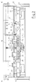
Figur 1- eine Arbeitswanne mit zwei Speisern, in Draufsicht;
Figur 2- einen Schnitt durch die Arbeitswanne gemäß
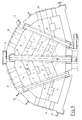
Figur 1, entlang der Schnittebene II - II inFigur 1; Figur 3- eine Arbeitswanne in anderer Konfiguration, mit vier Speisern, in Draufsicht;
Figur 4- einen scheitrechten Bogen in Seitenansicht;
Figur 5- einen Rührer im Oberbau der Decke, teils in Seitenansicht, teils im Schnitt,
Figur 6- eine Seitenansicht eines scheitrechten Bogens mit Haltetraverse,
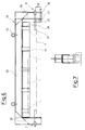
Figur 7- einen Schnitt durch den Gegenstand der
Figur 6 und Figur 8- eine Detailzeichnung des Anpreßteils der Traversenseitenstege.
- Figure 1
- a work tub with two feeders, in plan view;
- Figure 2
- a section through the work tank according to Figure 1, along the section plane II - II in Figure 1;
- Figure 3
- a work tub in another configuration, with four feeders, in plan view;
- Figure 4
- a bend right side view;
- Figure 5
- a stirrer in the superstructure of the ceiling, partly in side view, partly in section,
- Figure 6
- a side view of a right-angled arch with retaining crossbar,
- Figure 7
- a section through the subject of Figure 6 and
- Figure 8
- a detailed drawing of the pressing part of the truss side bars.
Bei einer Arbeitswanne 2 mit Speisern 30, 30' eines Glasschmelzofens mit einem von einer Strahlungsdecke 1 aus hochhitzebeständigem Ofenbaumaterial abgedeckten, Glasschmelze 18 bzw. 28 im Durchfluß enthaltenden Bassin 7 mit wenigstens einem an diesem angeordneten Speiser 30 besteht die erfindungswesetnlcihe Ausgestaltung der Decke 1 darin, daß diese mit die Arbeitswanne 2 in Abständen A, B, C überspannenden, die Last der Decke 1 aufnehmenden horizontalen Stützelementen 3 und die freien Abstände A, B, C zwischen den Stützelementen 3 überdeckenden, quer zwischen den Stützelementen 3 eingelegten horizontalen Abdeckplatten 4 ausgebildet ist.In the case of a working
Überraschend gelingt es mit der erfindungsgemäßen Aufteilung der Konstruktionselemente der Strahlungsdecke in lastaufnehmende horizontale Stützelemente 3 und die zwischenraumbedeckenden Abdeckplatten 4 eine tragende, flache Strahlungsdecke in vergleichsweise leichter Bauweise herzustellen.Surprisingly, with the inventive division of the structural elements of the radiation ceiling into load-bearing
In ganz besonderer Weise eignet sich dieses Deckensystem dafür, daß die sowohl für die Stützelemente 3 als auch für die Abdeckplatten 4 verwendeten einzelnen Steine nach Maßgabe ihrer Form bzw. Abmessung als Moduln eines Kollektivs bzw. einer Familie von Steinbauelementen ausgebildet sind. Diese Bauweise mit als Moduln ausgebildeten bzw. zusammengesetzten Bauelementen ergibt mit weiterem Vorteil, wie vorgängig erwähnt, die Möglichkeit, die Konstruktion als Computer aided design (CAD) durchzuführen, wodurch sich beträchtliche Vorteile hinsichtlich Konstruktionsaufwand, Zeitbedarf für die Konstruktion und Berechnung, sowie Reduzierung der Herstellungskosten durch Verwendung typisierter bzw. modulierter Einzelelemente ergibt.This ceiling system is particularly suitable for the fact that the individual stones used both for the
Wie aus der Zusammenschau der Draufsicht gemäß Figur 1 sowie der geschnittenen Darstellung gemäß Figur 2 hervorgeht, sind die zur Decke 1 der Arbeitswanne 2 in Modulnbauweise zusammengefügten Deckenbauelemente 3, 4 unter Vermeidung einer Deckenwölbung jeweils in horizontaler Erstreckung eine Flachdecke bildend mit einem lichten vertikalen Abstand von der Oberfläche 5 der Schmelze 29 zwischen 75 mm und 700 mm angeordnet. Wie weiter hierzu aus der Figur 4 erkennbar ist, sind die Stützelemente 3 jeweils als scheitrechte, gerade Bögen auf den Wandungen 6 des die Wanne 2 bildenden Bassins 7 aufliegend ausgebildet und angeordnet.As can be seen from the overview of the top view according to FIG. 1 and the sectional illustration according to FIG. 2, the
Ihre freie Tragfähigkeit erhalten die scheitrechten Bögen 3 dadurch, daß sie unter seitlicher, horizontaler Stützspannung zwischen seitlichen Widerlagern 8, 8' an den Stützträgern 9, 9' des Ofengerüstes 10 eingespannt sind. Dabei weisen die Widerlager 8, 8'Mittel 11 zum Einstellen der horizontalen Widerlagerspannung, vorzugsweise Spannschrauben auf, wie dies in den Figuren 4 und 5 rein symbolisch durch Pfeile dargestellt ist.The
Aus den Figuren 2 und 3 ist weiterhin erkennbar, daß die scheitrechten Bögen 3, 3', 3" mit jeweils seitlich abgetreppten Führungsbereichen 13, 13' ausgebildet und die Abdeckplatten 4 auf diese Führungsbereiche 13, 13' lose aufgelegt sind.It can also be seen from FIGS. 2 and 3 that the right-
Mit der erfindungsgemäßen Ausgestaltung der Strahlungsdecke oberhalb der Arbeitswanne ergibt sich eine besonders wirksame und somit erfindungswesentliche Ausbildung der Abdeckplatten 4 dadurch, daß diese auf den Führungsbereichen 13, 13' der scheitrechten Bögen 3 in zur Längsachse der Bögen paralleler Richtung verschiebbar sind (Fig. 1) und insbesondere dadurch, daß Abdeckplatten 4 mit abdeckbaren Öffnungen 14 ausgebildet sind.With the configuration of the radiation ceiling above the working trough according to the invention, a particularly effective and thus essential design of the
Wie die Betrachtung der Figuren 1 und 3 hierzu besonders deutlich erkennen lassen, können diese Öffnungen 14 in größerer Anzahl praktisch über das gesamte Areal der Strahlungsdecke verteilt sein. Sie geben somit die Möglichkeit, einerseits durch freigesetzte Öffnungen infolge Abstrahlung partielle Temperaturabsenkungen in der Schmelze einzustellen, mit der Einführung geeigneter Meßinstrumente Zustandsparameter der Schmelze wie Temperatur und Viskosität zu messen oder durch Einführen von an sich bekannten Heiz- oder Kühlelementen den Zustand der Schmelze im Durchlauf durch die Arbeitswanne erheblich und gezielt beeinflussen zu können. Ein weiterer Vorteil ergibt sich dadurch, daß örtlich auch Rührer eingesetzt werden können, welche durch Erzeugung eines örtlichen Konvektionssystems mit Badumwälzung zur Homogenisierung der Schmelzmasse beitragen. Ein derartiger Rührer ist rein beispielhaft in Figur 5 dargestellt.As can be seen particularly clearly from the observation of FIGS. 1 and 3, these
Weiterhin ist es infolge des erfindungsgemäßen Konstruktionssystems der Strahlungsdecke 1 möglich, daß Abdeckplatten 4, wie dies in Figur 2 gezeigt ist, von mobilen Haltevorrichtungen 15 verschiebbar gehalten sind. Eine solche Haltevorrichtung kann beispielsweise, wie dies rein schematisch gezeigt ist, eine bewegliche Zange aufweisen, die mittels eines bekannten Hebezeuges in einer hängenden Schienenbahn 32 verfahrbar ist. Damit gelingt es beispielsweise, wenn die Temperatur der Schmelze örtlich gesenkt werden soll, die eine oder andere Abdeckplatte 4 zeitweilig aus ihrer Lagerung herauszunehmen und beiseite zu legen. Hierzu ist besonders hilfreich und vorteilhaft, daß im Zusammenhang mit der erfindungsgemäßen Flachdeckenkonstruktion oberhalb der Flachdecke 1 eine am seitlichen Ofengerüst 10 aufgeständerte, horizontal die Flachdecke überspannende Arbeits- und Begehungsbühne 16 angeordnet ist.Furthermore, due to the construction system of the
Wie weiterhin aus der Zusammenschau der Figuren 2 mit den Figuren 1 und 3 erkennbar ist, eignet sich die Bühne im Zusammenwirken mit den Hauptmerkmalen der flachen Strahlungsdecke und wegen der unkomplizierten Zugänglichkeit der Schmelzenoberfläche 5 durch die Öffnungen 14 hindurch sehr vorteilhaft und unkompliziert zum Einsatz von Meßgeräten 17 beispielsweise zum Messen von Temperatur und/oder Viskosität der Glasschmelze 18 sowie von Heiz- oder Kühlelementen 19, Rührern 20 und/oder dergleichen Mitteln zur Beeinflussung und/oder Kontrolle von Zustandsparametern der Glasschmelze. Solche Elemente sind rein schematisch in Figur 1 angedeutet.As can further be seen from the combination of FIGS. 2 with FIGS. 1 and 3, the stage, in cooperation with the main features of the flat radiation ceiling and because of the uncomplicated accessibility of the
Und schließlich ist zur Temperierung der Glasschmelze vorgesehen, daß unterhalb der Flachdecke 1, vorzugsweise im Eckbereich 22 zwischen Decke 1 und Wandung 6 des Bassins 7, Brenner 23 bzw. Leisten 25 mit Brennerbatterien 24 vorgesehen sind.Finally, for tempering the glass melt, it is provided that beneath the
Zufolge der unterschiedlichen Beanspruchung der Konstruktionselemente 3 bzw. 4 der Strahlungsdecke 1 sind diese aus unterschiedlichen Feuerfestmaterialien hergestellt. Vorzugsweise sind die Abdeckplatten 4 aus hochtonerdehaltigem Feuerfestmaterial wie Sillimanit hergestellt. Weiterhin sind diese Abdeckplatten 4' gemäß Darstellung in Figur 1 Mitte, mit gebrochenen, insbesondere abgeschrägten, abgerundeten oder in anderer Weise abgefasten Kantenbereichen 26 ausgebildet. Dadurch wird erfolgreich die Gefahr des Abplatzens von Steinpartikeln im Bereich dieser Kanten, wleche das Glasschmelzbad verunreinigen könnten, vermieden.Due to the different loads on the
Weiter ist mit Vorteil vorgesehen, daß die Steinelemente 23 der scheitrechten Bögen 23 aus Feuerfestmaterial mit sehr hohem Kieselsäuregehalt wie Silika-Material hergestellt sind.It is also advantageously provided that the
Die erfindungsgemäße Ausbildung einer Arbeitswanne für einen Glasschmelzofen mit Speiser ist außerordentlich zweckmäßig und einfach. Mit Vorteil wird infolge dieser Ausgestaltung eine wirtschaftliche Bauweise ebenso ermöglicht, wie eine vollständige Möglichkeit zur Kontrolle und Beeinflussung der Parameter des geschmolzenen Glasgutes. Insofern kann von einer idealen Lösung der eingangs gestellten Aufgabe gesprochen werden.The inventive design of a work tub for a glass melting furnace with feeder is extremely useful and simple. As a result of this configuration, an economical construction is also advantageously made possible, as is a complete possibility of checking and influencing the parameters of the molten glass material. In this respect, one can speak of an ideal solution to the task at the beginning.
Gemäß den Zeichnungen 6 - 8 besteht die Erfindung auch darin, daß ein scheitrechter Bogen 3 aus Steinen aus Feuerfestmaterial, wie er seit langem bekannt ist, mittels eines Rahmens 32 nicht nur als Transporteinheit gestaltet wird, sondern daß er auch die bisherigen Nachteile vermeidet, während des Auftemperns und während des Betriebes besonderer Aufmerksamkeit zu bedürfen.According to the drawings 6-8, the invention also consists in the fact that a
Der scheitrechte Bogen 3 wird von einem aus einer Traverse 35 und beidseitig nach unten gerichteten Seitenstegen 36 bestehenden Rahmen 32 gehalten, der mittels Federpaketen 43 Längenausdehnungen während des Auftemperns ausgleichen kann.The right-
Die Federn 43, die beispielsweise als Tellerfedern ausgebildet sein können, sind in einem Hohlzylinder 40 angeordnet und werden durch eine Druckplatte 42, die über einen Schraubbolzen 41 in Position gehalten wird, vorgespannt.The
Die Kraft des Federpaketes 43 wirkt auf eine Druckplatte 33, die an den Stirnseiten des scheitrechten Bogens 3 anliegt. Durch die Ausdehnung der Federn wird dabei beim Auftempern gewährleistet, daß sowohl die Haltekraft des Bogens 3 erhalten bleibt, andererseits die Ausdehnung aber aufgenommen werden kann. Um auszuschließen, daß bei einer Ermüdung des Materials der Federn 43 ein Einsturz des scheitrechten Bogens erfolgt, werden die Druckplatten 33 mittels Schraubbolzen 39 nach dem Auftempern festgestellt, deren Freiraum so bemessen ist, daß sie sich in Andruckrichtung frei bewegen können, so daß sie bei einer Temperaturminderung das Verschieben der Andruckplatte 33 durch das Federpaket 43 nicht behindern. Die an den Seitenstegen 36 anliegende Spannschraube 47 drückt den Bolzen 39 gegen das Feuerfestmaterial des Bogens 3, ohne daß das andere Ende des Bolzens 39 eine Verschiebung zur Beibehaltung der Spannung des Bogens 3 behindern würde.The force of the
Um den scheitrechten Bogen als Transporteinheit zu gestalten, weist die obere Traverse 35 Heißaugen 34 auf und die Halterung des Bogens erfolgt über Haltebolzen 38, die in Bohrungen 37 in Feuerfestmaterial eindringen und von den seitlichen Stegen 36 gehalten werden.In order to design the log as a transport unit, the
Zur Einstellung der Längsflucht sind an der Traverse 35 U-förmige Profile 44 angebracht, die über isolierendes Schamotte 46 an den Feuerfest-Steinen angreifen. Da sie auf der Oberseite der Steine anliegen, wird gewährleistet, daß die Steine auch nicht unter Druck nach oben auswandern können. Damit wird der scheitrechte Bogen als beherrschbares, für sich berechenbares und transportables Bauelement geschaffen, der es ermöglicht, direkt eine Abdeckung über der Oberfläche der Glasschmelze zu schaffen. Durch die Schaffung von Öffnungen kann eine spezielle Kühlung z. B. vor dem Feeder erfolgen, es können aber auch, wie vorstehend genannt, Elemente für eine zusätzliche Heizung, zur Temperaturmessung, zur Rührung und dergleichen eingesetzt werden.To adjust the longitudinal alignment, 35
Da die zwischen den als Balken wirkenden scheitrechten Bögen eingesetzten Platten leicht auswechselbar sind und ein Stützgerüst über der Wannendecke nicht mehr erforderlich ist, können Reparaturen, Austausch oder Inspektion ohne Behinderungen vorgenommen werden.Since the plates inserted between the logs, which act as beams, are easily interchangeable and a support structure above the bathtub ceiling is no longer required repairs, exchanges or inspections can be carried out without hindrance.
Da auch eine Vorfertigung innerhalb eines Produktionsbetriebes und damit eine Standardisierung möglich ist, kann von einer idealen Lösung der anstehenden Probleme gesprochen werden.Since prefabrication within a production plant and thus standardization is also possible, one can speak of an ideal solution to the problems at hand.
Claims (17)
- A roof for a glass melting furnace or the working chamber, refining section or the like of a glass melting furnace (tank) of refractory material, the roof (1) being constructed with horizontal, spaced support elements (3) spanning the working chamber (2) and bearing the load from the roof (1) and cover plates (4) covering the free spaces between the support elements (3) and positioned transversely between the support elements (3), characterized in that- the support elements (3) are constructed and arranged as horizontal, straight bridges lying on the walls (6) of the tank (7) forming the chamber (2) and- the horizontal bridges (3) are held under lateral, horizontal supporting tension between lateral abutments (8, 8') on the supporting beams (9, 9') of the furnace frame (10) and- the individual stones used both for the support elements (3) and for the cover plates (4) are constructed according to their shape and dimensions as modules of a collective or family of stone structural members.
- A roof according to claim 1, characterized in that the structural roof members (3, 4) assembled in modular manner to form the roof (1) of the working chamber (2) are arranged in horizontal extension without arching to form a flat roof and at an internal vertical distance from the surface (5) of the melt of between 75 mm and 700 mm.
- A roof according to claim 1, characterized in that the abutments (8, 8') comprise means (11) for adjusting the horizontal abutment tension, preferably locking screws.
- A roof according to any one of claims 1 to 3, characterized in that the horizontal bridges (3, 3') are each constructed with laterally stepped guide areas (13, 13') and in that the cover plates (4) are laid loosely on these guide areas (13, 13').
- A roof according to any one of claims 1 to 4, characterized in that cover plates (4) can be displaced on the guide areas (13, 13') of the horizontal bridges (3) in the direction parallel to the longitudinal axis of the bridges.
- A roof according to any one of claims 1 to 5, characterized in that the cover plates (4) are constructed with coverable apertures (14).
- A roof according to any one of claims 1 to 6, characterized in that the cover plates (4) are held displaceably by mobile holding devices (15).
- A roof according to any one of claims 1 to 7, characterized in that above the flat roof (1) there is arranged a working and walking platform (16) standing on the lateral furnace frame (10) and horizontally spanning the flat roof (1).
- A roof according to any one of claims 1 to 8, characterized in that the cover plates (4) are constructed with broken, especially bevelled, rounded or otherwise chamfered edge areas (26).
- A roof according to any one of claims 1 to 9, characterized in that stone members (17) of the horizontal bridges are constructed with stepped supporting surfaces (28, 29).
- A roof according to any one of claims 1 to 10, characterized in that the abutments (8, 9) for the horizontal bridges (3) are constructed on a frame (32) spanning the girders (3), which frame (32) consists of a crossbar (35) and side webs (36) directed downwards on both sides.
- A roof according to claim 11, characterized in that the frame (32) comprises prestressable pressure plates (33) for resting on the ends of the girders (3).
- A roof according to either of claims 11 or 12, characterized in that the frame comprises hoist lugs (34) on its crossbar (35) and retaining bolts (38) inserted in bores (37) on the side webs (36) to form a transportation unit.
- A roof according to claim 12, characterized in that the side webs (36) comprise pressure plates (33) and bolts (39) fixing the bridge in continuous operation.
- A roof according to claim 12, characterized in that to press the pressure plates (33) a hollow cylinder (40) connected therewith and under spring loading is provided, and in that a pressure plate (42) adjusting the spring loading by means of a screw bolt (41) rests on a spring assembly (43) arranged between the hollow cylinder (40) and the pressure plate.
- A roof according to claim 12, characterized in that U-shaped iron sections (44) are arranged under the crossbar (35), the lateral webs (45) of which iron sections (44) rest on the upper areas of the refractory material of the girders (3).
- A roof according to claim 16, characterized in that insulating fireclay (46) is arranged between the webs (45) and the refractory material.
Applications Claiming Priority (5)
| Application Number | Priority Date | Filing Date | Title |
|---|---|---|---|
| DE19863615276 DE3615276A1 (en) | 1986-05-06 | 1986-05-06 | Working end of a glass melting furnace |
| DE3615276 | 1986-05-06 | ||
| DE19873711045 DE3711045A1 (en) | 1986-05-06 | 1987-04-06 | Cover for a glass-melting furnace or working bath |
| DE3711045 | 1987-04-06 | ||
| CA000558537A CA1330164C (en) | 1986-05-06 | 1988-02-05 | Roof for working area, melting area or gob feeder of a glass melting furnace |
Publications (3)
| Publication Number | Publication Date |
|---|---|
| EP0244710A2 EP0244710A2 (en) | 1987-11-11 |
| EP0244710A3 EP0244710A3 (en) | 1989-08-02 |
| EP0244710B1 true EP0244710B1 (en) | 1992-01-29 |
Family
ID=27167873
Family Applications (1)
| Application Number | Title | Priority Date | Filing Date |
|---|---|---|---|
| EP87106005A Expired - Lifetime EP0244710B1 (en) | 1986-05-06 | 1987-04-24 | Roof for a glass melting furnace or a working chamber |
Country Status (6)
| Country | Link |
|---|---|
| US (1) | US4836841A (en) |
| EP (1) | EP0244710B1 (en) |
| AT (1) | ATE72211T1 (en) |
| CA (1) | CA1330164C (en) |
| DE (3) | DE3615276A1 (en) |
| ES (1) | ES2029807T3 (en) |
Families Citing this family (5)
| Publication number | Priority date | Publication date | Assignee | Title |
|---|---|---|---|---|
| US5007950A (en) * | 1989-12-22 | 1991-04-16 | Ppg Industries, Inc. | Compressed, wedged float glass bottom structure |
| US20160238279A1 (en) * | 2015-02-13 | 2016-08-18 | Corning Incorporated | Methods of processing a furnace |
| SI3431447T1 (en) * | 2017-07-21 | 2020-07-31 | Engie | A method of melting raw materials such as glass by a cross-fired melting furnace |
| CN107576200A (en) * | 2017-09-21 | 2018-01-12 | 贵州航天新力铸锻有限责任公司 | The laying method of the drop-bottom of trolley type heating furnace |
| KR102415723B1 (en) * | 2017-11-20 | 2022-07-04 | 코닝 인코포레이티드 | Molten material stirring system and Method for stirring the material |
Family Cites Families (15)
| Publication number | Priority date | Publication date | Assignee | Title |
|---|---|---|---|---|
| US1339615A (en) * | 1916-12-14 | 1920-05-11 | Wundrack Otto | Flat arch for furnaces |
| US1949380A (en) * | 1929-11-05 | 1934-02-27 | Owens Illinois Glass Co | Glass furnace |
| DE639573C (en) * | 1933-11-15 | 1936-12-08 | Josef Watzula | Glass melting furnace |
| US2773111A (en) * | 1948-01-23 | 1956-12-04 | Saint Gobain | Method and apparatus for manufacturing glass |
| US2834306A (en) * | 1952-02-26 | 1958-05-13 | Pilkington Brothers Ltd | Furnaces |
| DE1015976B (en) * | 1956-02-09 | 1957-09-19 | Bbc Brown Boveri & Cie | Suspended ceilings for industrial ovens, cooling chambers or the like with large dimensions |
| DE1130116B (en) * | 1959-06-26 | 1962-05-24 | Georges Henry | Device for regulating the operation of glass melting furnace furnaces |
| US3134199A (en) * | 1960-05-19 | 1964-05-26 | North American Refractories | Complexed refractory brick |
| US3248203A (en) * | 1961-10-30 | 1966-04-26 | Owens Corning Fiberglass Corp | Apparatus for heat control of forehearths |
| FR1317242A (en) * | 1961-11-27 | 1963-02-08 | Glaces De Boussois | Improvements to installations for the manufacture of flat glass |
| US3201219A (en) * | 1962-06-01 | 1965-08-17 | Frazier Simplex | Glass melting furnace |
| DE2203944A1 (en) * | 1972-01-28 | 1973-08-02 | Schulte Fa D W | Joining of refractory elements - with dove -tailed and rectangular refractory elements slotting into upper side recesses |
| IT8322362V0 (en) * | 1983-07-14 | 1983-07-14 | Siti | SUPPORT STRUCTURES FOR TIMES OF OVENS. |
| US4622059A (en) * | 1985-10-08 | 1986-11-11 | Emhart Industries, Inc. | Apparatus for controlling temperature within a forehearth |
| US4704155A (en) * | 1986-06-11 | 1987-11-03 | Ppg Industries, Inc. | Heating vessel lid construction for a glass melting furnace |
-
1986
- 1986-05-06 DE DE19863615276 patent/DE3615276A1/en active Granted
-
1987
- 1987-04-06 DE DE19873711045 patent/DE3711045A1/en not_active Withdrawn
- 1987-04-24 DE DE8787106005T patent/DE3776397D1/en not_active Expired - Fee Related
- 1987-04-24 ES ES198787106005T patent/ES2029807T3/en not_active Expired - Lifetime
- 1987-04-24 AT AT87106005T patent/ATE72211T1/en not_active IP Right Cessation
- 1987-04-24 EP EP87106005A patent/EP0244710B1/en not_active Expired - Lifetime
- 1987-04-29 US US07/043,872 patent/US4836841A/en not_active Expired - Lifetime
-
1988
- 1988-02-05 CA CA000558537A patent/CA1330164C/en not_active Expired - Fee Related
Also Published As
| Publication number | Publication date |
|---|---|
| EP0244710A2 (en) | 1987-11-11 |
| ATE72211T1 (en) | 1992-02-15 |
| DE3776397D1 (en) | 1992-03-12 |
| DE3615276C2 (en) | 1988-03-10 |
| DE3711045A1 (en) | 1988-10-27 |
| ES2029807T3 (en) | 1992-10-01 |
| EP0244710A3 (en) | 1989-08-02 |
| US4836841A (en) | 1989-06-06 |
| CA1330164C (en) | 1994-06-14 |
| DE3615276A1 (en) | 1987-11-19 |
Similar Documents
| Publication | Publication Date | Title |
|---|---|---|
| DE2203360A1 (en) | Kiln car | |
| EP0232842B1 (en) | Element construction, in particular wall and ceiling elements | |
| EP0067451B1 (en) | Tunnel kiln truck | |
| EP0385923B1 (en) | Structural member for the construction of buildings, parts of buildings or the like | |
| EP0244710B1 (en) | Roof for a glass melting furnace or a working chamber | |
| DE3839346C1 (en) | ||
| EP3355015B1 (en) | Support elements for a tunnel furnace cart or carriage, tunnel furnace cart or carriage with such support elements and tunnel furnace with such a tunnel furnace cart or carriage | |
| DE3832358C2 (en) | ||
| DE4039601C2 (en) | ||
| DE1433463A1 (en) | Vaulted oven ceiling | |
| DE2325529C2 (en) | HANGING CEILING FOR INDUSTRIAL STOVES | |
| EP0317494A2 (en) | Coke oven door with a ceramic shield construction | |
| DE2540401B2 (en) | Fireproof tunnel furnace in sandwich construction | |
| DE2838024A1 (en) | WASTE PRE-HEATER | |
| EP3296476A1 (en) | Assembly for connecting a building wall with a floor or ceiling plate and form block for such an assembly | |
| DE3328870A1 (en) | OVEN CAR FOR FURNACE | |
| DE2455296C3 (en) | Wall with supports and wall panels attached to them | |
| DE4301841C2 (en) | Periodic oven | |
| DE2403266B1 (en) | ||
| DE2923612A1 (en) | HEAT TREATMENT | |
| DE3807243C1 (en) | Suspension device for gas-permeable partition walls | |
| EP1772672A1 (en) | Device for cooling exhaust gases | |
| EP0545018B1 (en) | Channel for regulating the temperature of a current of meltable material | |
| EP2187156B1 (en) | Suspended ceiling system for interior cladding of ovens | |
| DE2345255C3 (en) | Device for carrying out control and maintenance work on a pouring ladle |
Legal Events
| Date | Code | Title | Description |
|---|---|---|---|
| PUAI | Public reference made under article 153(3) epc to a published international application that has entered the european phase |
Free format text: ORIGINAL CODE: 0009012 |
|
| AK | Designated contracting states |
Kind code of ref document: A2 Designated state(s): AT BE CH DE ES FR GB IT LI NL SE |
|
| PUAL | Search report despatched |
Free format text: ORIGINAL CODE: 0009013 |
|
| AK | Designated contracting states |
Kind code of ref document: A3 Designated state(s): AT BE CH DE ES FR GB IT LI NL SE |
|
| 17P | Request for examination filed |
Effective date: 19890914 |
|
| RAP1 | Party data changed (applicant data changed or rights of an application transferred) |
Owner name: BETEILIGUNGEN SORG GMBH & CO. KG |
|
| 17Q | First examination report despatched |
Effective date: 19900720 |
|
| RAP1 | Party data changed (applicant data changed or rights of an application transferred) |
Owner name: BETEILIGUNGEN SORG GMBH & CO. KG |
|
| GRAA | (expected) grant |
Free format text: ORIGINAL CODE: 0009210 |
|
| AK | Designated contracting states |
Kind code of ref document: B1 Designated state(s): AT BE CH DE ES FR GB IT LI NL SE |
|
| REF | Corresponds to: |
Ref document number: 72211 Country of ref document: AT Date of ref document: 19920215 Kind code of ref document: T |
|
| ITF | It: translation for a ep patent filed |
Owner name: DE DOMINICIS & MAYER S.R.L. |
|
| ET | Fr: translation filed | ||
| GBT | Gb: translation of ep patent filed (gb section 77(6)(a)/1977) | ||
| REF | Corresponds to: |
Ref document number: 3776397 Country of ref document: DE Date of ref document: 19920312 |
|
| PLBI | Opposition filed |
Free format text: ORIGINAL CODE: 0009260 |
|
| REG | Reference to a national code |
Ref country code: ES Ref legal event code: FG2A Ref document number: 2029807 Country of ref document: ES Kind code of ref document: T3 |
|
| 26 | Opposition filed |
Opponent name: FIRMA HERMANN HEYE Effective date: 19920912 |
|
| NLR1 | Nl: opposition has been filed with the epo |
Opponent name: FIRMA HERMANN HEYE. |
|
| PLBN | Opposition rejected |
Free format text: ORIGINAL CODE: 0009273 |
|
| STAA | Information on the status of an ep patent application or granted ep patent |
Free format text: STATUS: OPPOSITION REJECTED |
|
| 27O | Opposition rejected |
Effective date: 19930321 |
|
| NLR2 | Nl: decision of opposition | ||
| EAL | Se: european patent in force in sweden |
Ref document number: 87106005.9 |
|
| PGFP | Annual fee paid to national office [announced via postgrant information from national office to epo] |
Ref country code: CH Payment date: 19970325 Year of fee payment: 11 |
|
| PGFP | Annual fee paid to national office [announced via postgrant information from national office to epo] |
Ref country code: SE Payment date: 19970327 Year of fee payment: 11 |
|
| PGFP | Annual fee paid to national office [announced via postgrant information from national office to epo] |
Ref country code: BE Payment date: 19980319 Year of fee payment: 12 |
|
| PG25 | Lapsed in a contracting state [announced via postgrant information from national office to epo] |
Ref country code: SE Free format text: LAPSE BECAUSE OF NON-PAYMENT OF DUE FEES Effective date: 19980425 |
|
| PG25 | Lapsed in a contracting state [announced via postgrant information from national office to epo] |
Ref country code: LI Free format text: LAPSE BECAUSE OF NON-PAYMENT OF DUE FEES Effective date: 19980430 Ref country code: CH Free format text: LAPSE BECAUSE OF NON-PAYMENT OF DUE FEES Effective date: 19980430 |
|
| PGFP | Annual fee paid to national office [announced via postgrant information from national office to epo] |
Ref country code: NL Payment date: 19980430 Year of fee payment: 12 |
|
| REG | Reference to a national code |
Ref country code: CH Ref legal event code: PL |
|
| EUG | Se: european patent has lapsed |
Ref document number: 87106005.9 |
|
| PG25 | Lapsed in a contracting state [announced via postgrant information from national office to epo] |
Ref country code: BE Free format text: LAPSE BECAUSE OF NON-PAYMENT OF DUE FEES Effective date: 19990430 |
|
| BERE | Be: lapsed |
Owner name: BETEILIGUNGEN SORG G.M.B.H. & CO. K.G. Effective date: 19990430 |
|
| PG25 | Lapsed in a contracting state [announced via postgrant information from national office to epo] |
Ref country code: NL Free format text: LAPSE BECAUSE OF NON-PAYMENT OF DUE FEES Effective date: 19991101 |
|
| NLV4 | Nl: lapsed or anulled due to non-payment of the annual fee |
Effective date: 19991101 |
|
| PGFP | Annual fee paid to national office [announced via postgrant information from national office to epo] |
Ref country code: FR Payment date: 20000321 Year of fee payment: 14 Ref country code: DE Payment date: 20000321 Year of fee payment: 14 |
|
| PGFP | Annual fee paid to national office [announced via postgrant information from national office to epo] |
Ref country code: ES Payment date: 20000407 Year of fee payment: 14 |
|
| PGFP | Annual fee paid to national office [announced via postgrant information from national office to epo] |
Ref country code: AT Payment date: 20000412 Year of fee payment: 14 |
|
| PGFP | Annual fee paid to national office [announced via postgrant information from national office to epo] |
Ref country code: GB Payment date: 20000419 Year of fee payment: 14 |
|
| PG25 | Lapsed in a contracting state [announced via postgrant information from national office to epo] |
Ref country code: GB Free format text: LAPSE BECAUSE OF NON-PAYMENT OF DUE FEES Effective date: 20010424 Ref country code: AT Free format text: LAPSE BECAUSE OF NON-PAYMENT OF DUE FEES Effective date: 20010424 |
|
| PG25 | Lapsed in a contracting state [announced via postgrant information from national office to epo] |
Ref country code: ES Free format text: LAPSE BECAUSE OF NON-PAYMENT OF DUE FEES Effective date: 20010425 |
|
| PG25 | Lapsed in a contracting state [announced via postgrant information from national office to epo] |
Ref country code: FR Free format text: THE PATENT HAS BEEN ANNULLED BY A DECISION OF A NATIONAL AUTHORITY Effective date: 20010430 |
|
| GBPC | Gb: european patent ceased through non-payment of renewal fee |
Effective date: 20010424 |
|
| PG25 | Lapsed in a contracting state [announced via postgrant information from national office to epo] |
Ref country code: DE Free format text: LAPSE BECAUSE OF NON-PAYMENT OF DUE FEES Effective date: 20020201 |
|
| REG | Reference to a national code |
Ref country code: FR Ref legal event code: ST |
|
| REG | Reference to a national code |
Ref country code: ES Ref legal event code: FD2A Effective date: 20030303 |
|
| PG25 | Lapsed in a contracting state [announced via postgrant information from national office to epo] |
Ref country code: IT Free format text: LAPSE BECAUSE OF NON-PAYMENT OF DUE FEES;WARNING: LAPSES OF ITALIAN PATENTS WITH EFFECTIVE DATE BEFORE 2007 MAY HAVE OCCURRED AT ANY TIME BEFORE 2007. THE CORRECT EFFECTIVE DATE MAY BE DIFFERENT FROM THE ONE RECORDED. Effective date: 20050424 |