EP0243979A2 - Elektromagnetisches Kleinstrelais - Google Patents
Elektromagnetisches Kleinstrelais Download PDFInfo
- Publication number
- EP0243979A2 EP0243979A2 EP87106329A EP87106329A EP0243979A2 EP 0243979 A2 EP0243979 A2 EP 0243979A2 EP 87106329 A EP87106329 A EP 87106329A EP 87106329 A EP87106329 A EP 87106329A EP 0243979 A2 EP0243979 A2 EP 0243979A2
- Authority
- EP
- European Patent Office
- Prior art keywords
- chamber
- module
- electromagnetic relay
- modules
- assembly
- Prior art date
- Legal status (The legal status is an assumption and is not a legal conclusion. Google has not performed a legal analysis and makes no representation as to the accuracy of the status listed.)
- Granted
Links
Images

Classifications
-
- H—ELECTRICITY
- H01—ELECTRIC ELEMENTS
- H01H—ELECTRIC SWITCHES; RELAYS; SELECTORS; EMERGENCY PROTECTIVE DEVICES
- H01H50/00—Details of electromagnetic relays
- H01H50/02—Bases; Casings; Covers
- H01H50/021—Bases; Casings; Covers structurally combining a relay and an electronic component, e.g. varistor, RC circuit
-
- H—ELECTRICITY
- H01—ELECTRIC ELEMENTS
- H01H—ELECTRIC SWITCHES; RELAYS; SELECTORS; EMERGENCY PROTECTIVE DEVICES
- H01H50/00—Details of electromagnetic relays
- H01H50/02—Bases; Casings; Covers
- H01H50/023—Details concerning sealing, e.g. sealing casing with resin
Definitions
- the innovation relates to electromagnetic relay, in particular miniature relay, which are assigned to circuit-electronic components or modules or circuits thereof are coordinate, and consequently, 'such a relay should next be accommodated.
- the present innovation is based on known relay constructions in which the spring bracket and / or the base plate is formed from insulating material and serves as the basis for the construction of the relay with a magnetic and spring contact system.
- This innovation was based on the task of accommodating modules in a simple manner on or in the relay in a space-saving, protected and insulated manner in such a way that assembly can also be carried out without any particular effort.
- a chamber designed to accommodate modules is formed and arranged in such a way that the connecting pins of the module or modules after equipping and locking the chamber are aligned and aligned with the connecting ends of the contact spring set and / or the coil connections can be contacted.
- the chamber with an opening on the bottom or connection side for the module assembly in the spring bock or the base plate is molded, which is hermetically sealed after assembly by a snap-in end plate, by casting or the like.
- the chamber is formed with bottom-side bushings for the connection pins of the modules and with a lateral insertion opening for the module assembly in the spring bracket or the base plate, which, after the assembly, encloses the relay up to the connection side Cap or hood is closed.
- the modules are insulated and are safely accommodated from mechanical damage from the outside in a space closed on all sides after the insertion opening has been closed.
- the connection pins of the modules are led out on the same side and in the same direction as the other connections of the relay, which means that the relay can be easily installed even when the circuit board is equipped with such a relay.
- the modules can be fixed very easily on the inside of the chamber, for example by means of locking lugs which are already provided in the molded part, or by casting, the insertion opening of the chamber being able to be closed at the same time with the casting.
- Other options for closing the chamber opening are provided by a separate snap-in closing plate or, in the case of a side insertion opening, by the cover cap which is usually associated with the relay.
- the inside of the chamber is accommodated in a cassette which is closed on all sides for accommodating one Module or electronic module is formed, and has latching lugs on the edge of the insertion opening, on which the cassette module, which preferably fills the volume of the chamber, is latched in the chamber.
- a known embodiment of a relay is shown in simplified form in FIG.
- a magnet system 1 pivotably supports the armature 2 on one end face, which has the spring contact with its free end applied to the contact set 3, the spring contacts are in turn fixed in a spring bracket 4.
- a chamber 8 is formed in such a way that the connections of the electronic module or module 9 to be inserted into this chamber come out from the spring bracket 4 in the same direction and in the same direction as the connecting lugs 7 of the spring contact set 3 and the coil connections 6 of the magnet system 1 and can be contacted
- FIG. 2 shows an embodiment of a relay designed for high safety requirements with regard to creepage distances and clearances, whose magnet system 1 with coil connection carrier and armature 2 is inserted into a cassette which is closed on all sides, the armature 2 actuating the changeover contact spring of the spring contact set 3 via an actuating web.
- the spring bracket 4 is designed with the cassette-like housing for the magnet system 1 as a one-piece molded part, the chamber 8 being arranged and molded in the lower region of this molded part, which can also be referred to as the base plate 5, similar to that of FIG.
- connections or connecting pins 10 of the module 9 arranged in this chamber 8 are here also on the same side and rectified with the connecting lugs 7 of the spring contact set 3 and the coil connections 6 of the magnet system and can be contacted at the same level
- the module 9 is fixed on or between locking noses 11 molded into the inside of the chamber 9. It can also be seen from this that the insertion opening for the module 9 on the bottom or on the side can be arranged or provided. In the case of a bottom-side opening for the insertion of the module 9, the opening can be closed or glued in by an end plate. Another possibility is that the chamber 8 is poured out with a mass known per se.
- the chamber 8 can also be formed with a lateral opening, the connections or connecting pins 10 of the module 9 used being aligned in the same way as the connections 7 and / or 6 of the spring contact system 3 or, respectively, by corresponding bottom-side bushings. of the magnet system 1 are brought out.
- a cover of the relay which is not shown, which is pushed over to the lower edge of the spring bracket 4 of FIG. 4 or the cash-type housing 5 of FIG. 2, closes this lateral opening of the chamber 8.
- a further advantageous embodiment according to the innovation can be achieved by introducing into this chamber 8 a module 9 arranged or embedded in a miniature housing in cassette form as a self-contained unit and being fixed in this chamber 8 by means of correspondingly arranged latching lugs 11.
Landscapes
- Physics & Mathematics (AREA)
- Electromagnetism (AREA)
- Switch Cases, Indication, And Locking (AREA)
- Connecting Device With Holders (AREA)
- Casings For Electric Apparatus (AREA)
- Details Of Connecting Devices For Male And Female Coupling (AREA)
- Electrophonic Musical Instruments (AREA)
- Control Of Motors That Do Not Use Commutators (AREA)
- Developing Agents For Electrophotography (AREA)
Abstract
Description
- Die Neuerung bezieht sich auf elektromagnetische Relais, insbesondere Kleinstrelais, denen elektronische Bausteine oder Module schaltungstechnisch zugeordnet werden oder deren Schaltkreisen beigeordnet sind, und folglich nächst 'einem solchen Relais untergebracht werden sollten.
- Die vorliegende Neuerung setzt von an sich bekannten Relaiskonstruktionen aus, in denen der Federbock und/oder die Bodenplatte aus isolierendem Material geformt ist und als Basis für den Aufbau des Relais mit Magnet- und Federköntaktsystem dient.
- Dieser Neuerung lag nun die Aufgabe zugrunde, auf einfache Weise zuzuordnende Module am oder im Relais platzsparend, geschützt und isoliert so unterzubringen, daß auch eine Montage ohne besonderen Aufwand erfolgen kann.
- Gemäß der Neuerung ist deshalb vorgesehen, daß im Federbock oder der Bodenplatte des Relais eine zur Aufnahme von Modulen geeignet ausgebildete Kammer eingeformt und so angeordnet ist, daß die Anschlußstifte des oder der Module nach der Bestückung und dem Verschluß der Kammer gleichseitig und gleichgerichtet mit den Anschlußenden des Kontaktfedersatzes und/oder den Spulenanschlüssen kontaktierbar sind.
- In der weiteren Ausbildung der Neuerung ist dann vorgesehen, daß die Kammer mit einer boden- oder anschlußseitigen öffnung für die Modulbestückung in den Federbock oder die Bodenplatte eingeformt ist, die nach der Bestückung durch eine einrastbare Abschlußplatte, durch Vergießen oder dgl. hermetisch verschlossen wird.
- In einer anderen Ausführungsform ist vorgesehen, daß die Kammer mit bodenseitigen Durchführungen für die Anschlußstifte der Module und mit einer seitlichen Einschuböffnung für die Modul-Bestückung in den Federbock oder die Bodenplatte eingeformt ist, die nach der Bestückung durch eine das Relais bis auf die Anschlußseite umschließende Kappe oder Haube verschlossen wird.
- Mit einer solchen bereits im Federbock- oder Bodenplatten-Formteil vorgesehenen Kammer sind die Module isoliert und vor mechanischen Beschädigungen von außen sicher in einem nach Verschließen der Einschuböffnung allseitig geschlossenen Raum untergebracht. Die Anschlußstifte der Module sind bei beiden bevorzugten Ausführungsformen gleichseitig und gleichgerichtet mit den anderen Anschlüssen des Relais herausgeführt, wodurch auch bei einer Platinenbestückung eines solchen Relais eine einfache Montage des Relais gegeben ist.
- Die Module können sehr einfach innenseitig der Kammer festgelegt werden, so zum Beispiel mittels Rastnasen, die bereits im Formteil vorgesehen werden, oder, durch Vergiessen, wobei mit dem Vergießen gleichzeitig die Einschuböffnung der Kammer verschlossen werden kann. Andere Möglichkeiten des Abschlusses der Kammeröffnung sind durch eine separate einrastbare Abschlußplatte, oder, bei seitlicher Einschuböffnung, durch die dem Relais zumeist zugeordnete überstreifbare Abdeckkappe gegeben.
- Als weitere Variante ist gemäß der Neuerung vorgesehen, daß die Innenseiten der Kammer für die Aufnahme eines in einer allseitig geschlossenen Kassette untergebrachten Moduls oder elektronischen Bausteins ausgebildet ist, und am Rand der Einschuböffnung Rastnasen aufweist, an denen der das Volumen der Kammer vorzugsweise füllende Kassettenmodul einrastend in der Kammer festgelegt wird.
- Mit einem bereits in einem kassettenartigen Gehäuse gekapselt untergebrachten Modul wird die Montage des Relais selbst,unter Wegfall des Vergießens und/oder Verschließens der Kammeröffnung,weiter merklich vereinfacht.
- Wesentlich ist, daß gegenüber den bisherigen Montageverfahren mit der Anordnung der Module in einer allseitig geschlossenen Kammer in einem Formteil des Relais, der Herstellungs- und Montageaufwand bedeutsam verringert werden kann.
- Die Neuerung wird nun nachfolgend anhand von zwei in den Zeichnungsfiguren dargestellten bevorzugten Ausführungsbeispielen näher beschrieben.
- In den Zeichnungen zeigt -
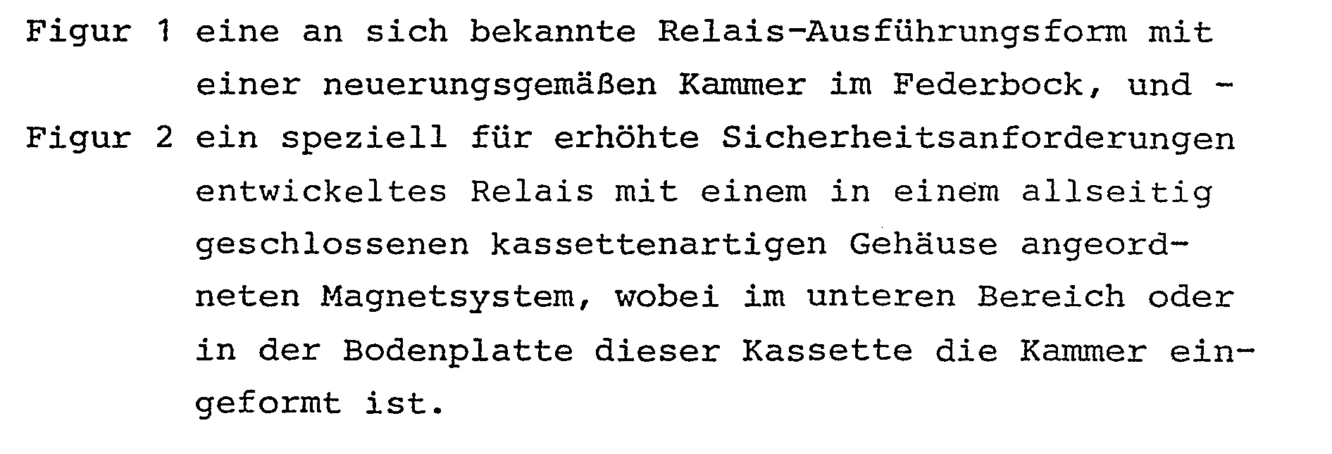
- In der Figur 1 ist eine an sich bekannte Ausführungsform eines Relais vereinfacht dargestellt. Ein Magnetsystem 1 trägt an einer Stirnseite verschwenkbar den Anker 2, der mit seinem freien Ende die Schaltkontaktfeder des Federkontaktsatzes 3 beaufschlagt, dessen Federkontakte wiederum in einem Federbock 4 festgelegt sind. Im Federbock 4 ist eine Kammer 8 derart eingeformt, daß die Anschlüsse des in diese Kammer einzusetzenden elektronischen Bausteins oder Moduls 9 gleichseitig und gleichgerichtet mit den Anschlußfahnen 7 des Federkontaktsatzes 3 und den Spulenanschlüssen 6 des Magnetsystems ' 1 aus dem Federbock 4 heraustreten und kontaktierbar sind
- In der Figur 2 ist eine für hohe Sicherheitsanforderungen bezüglich Kriech- und Luftstrecken ausgelegte Ausführungsform eines Relais dargestellt, dessen Magnetsystem 1 mit Spulenanschlußträger und Anker 2 in eine allseitig geschlossene Kassette eingeschoben wird, wobei der Anker 2 über einen Betätigungssteg die Umschaltkontaktfeder des Federkontaktsatzes 3 betätigt. Der Federbock 4 ist bei dieser Ausführungsform mit dem kassettenartigen Gehäuse für das Magnetsystem 1 als einstückiges Formteil ausgeführt, wobei im unteren Bereich dieses auch als Bodenplatte 5 zu bezeichnenden Formteils die Kammer 8 ähnlich der der Figur 1 angeordnet und eingeformt ist.
- Die Anschlüsse oder Anschlußstifte 10 des in dieser Kammer 8 angordneten Moduls 9 sind hier ebenfalls gleichseitig und gleichgerichtet mit den Anschlußfahnen 7 des Federkontaktsatzes 3 und den Spulenanschlüssen 6 des Magnetsystems herausgeführt und auf gleicher Ebene kontaktierbar
- Aus beiden Figuren geht hervor, daß, bezogen auf die Darstellung in den Figuren, der Modul 9 an oder zwischen innenseitig der Kammer 9 eingeformten Rastnasen 11 festgelegt ist. Es ist auch daraus ersichtlich, daß die Einschuböffnung für den Modul 9 bodenseitig oder seitlich angeordnet oder vorgesehen werden kann. Bei einer bodenseitigen Öffnung für den Einschub des Moduls 9 kann die Öffnung durch eine Abschlußplatte einrastbar oder einklebbar verschlossen.werden. Eine andere Möglichkeit besteht darin, daß die Kammer 8 mit einer an sich bekannten Masse ausgegossen wird.
- Aus beiden dargestellten Ausführungsformen kann auch entnommen werden, daß die Kammer 8 auch mit einer seitlichen öffnung ausgebildet werden kann, wobei die Anschlüsse oder Anschlußstifte 10 des eingesetzten Moduls 9 durch entsprechende bodenseitige Durchführungen gleichgerichtet mit den Anschlüssen 7 und/oder 6 des Federkontaktsystems 3 bzw. des Magnetsystems 1 herausgeführt sind. Mit einer seitlichen Einschuböffnung bietet sich zudem noch an, daß eine zwar nicht dargestellte Haube des Relais, die bis zur Unterkante des Federbocks 4 der Figur 4 bzw. des kassenartigen Gehäuses 5 der Figur 2 übergeschoben wird, diese seitliche öffnung der Kammer 8 verschließt.
- Eine weitere vorteilhafte Ausbildung gemäß der Neuerung kann dadurch erreicht werden, in dem in diese Kammer 8 ein in einem Miniaturgehäuse in Kassettenform angeordneter oder eingebetteter Modul 9 als in sich geschlossene Einheit eingebracht und in dieser Kammer 8 durch entsprechend angeordnete Rastnasen 11 festgelegt wird.
- Weitere Kombinationsmöglichkeiten der beanspruchten Merkmale lassen sich aus der Beschreibung im Zusammenhang mit den dargestellten Ausführungsformen herleiten.
- Die neuerungsgemäßen Merkmale sind auch für Relais mit einem gegenüber den dargestellten und beschriebenen Ausführungsformen konstruktiv anderen Aufbau anwendbar.
-
- 1 Magnetsystem
- 2 Anker
- 3 Federkontaktsatz
- 4 Federbock
- 5 Bodenplatte
- 6 Spulenanschlüsse
- 7 Anschlußenden des 3
- 8 Kammer
- 9 Module
- 10 Anschlußstifte 7 9
- 11 Rastnasen
Claims (5)
Priority Applications (1)
| Application Number | Priority Date | Filing Date | Title |
|---|---|---|---|
| AT87106329T ATE73262T1 (de) | 1986-05-02 | 1987-05-01 | Elektromagnetisches kleinstrelais. |
Applications Claiming Priority (2)
| Application Number | Priority Date | Filing Date | Title |
|---|---|---|---|
| DE3614919 | 1986-05-02 | ||
| DE19863614919 DE3614919A1 (de) | 1986-05-02 | 1986-05-02 | Elektromagnetisches kleinstrelais |
Publications (3)
| Publication Number | Publication Date |
|---|---|
| EP0243979A2 true EP0243979A2 (de) | 1987-11-04 |
| EP0243979A3 EP0243979A3 (en) | 1989-08-23 |
| EP0243979B1 EP0243979B1 (de) | 1992-03-04 |
Family
ID=6300043
Family Applications (1)
| Application Number | Title | Priority Date | Filing Date |
|---|---|---|---|
| EP87106329A Expired - Lifetime EP0243979B1 (de) | 1986-05-02 | 1987-05-01 | Elektromagnetisches Kleinstrelais |
Country Status (3)
| Country | Link |
|---|---|
| EP (1) | EP0243979B1 (de) |
| AT (1) | ATE73262T1 (de) |
| DE (2) | DE3614919A1 (de) |
Cited By (5)
| Publication number | Priority date | Publication date | Assignee | Title |
|---|---|---|---|---|
| EP0345363A1 (de) * | 1988-06-04 | 1989-12-13 | Weidmüller Interface GmbH & Co. | Anreihbares Einbaugehäuse |
| EP0394804A1 (de) * | 1989-04-27 | 1990-10-31 | Eh- Schrack Components-Aktiengesellschaft | Stecksockel zur Aufnahme eines Relais |
| EP0507729A3 (en) * | 1991-04-05 | 1993-05-19 | Elesta Ag Elektronik | Plug-in relay and additional module wit matching relay fitting |
| ES2040621A2 (es) * | 1991-09-13 | 1993-10-16 | Releco Sa | Mejoras introducidas en reles electromagneticos. |
| EP2503582A1 (de) * | 2011-03-23 | 2012-09-26 | Panasonic Corporation | Elektromagnetisches Relais |
Families Citing this family (7)
| Publication number | Priority date | Publication date | Assignee | Title |
|---|---|---|---|---|
| DE3823184A1 (de) * | 1988-07-08 | 1990-01-11 | Messerschmitt Boelkow Blohm | Elektrisches bauelement |
| DE4005809A1 (de) * | 1990-02-23 | 1991-08-29 | Siemens Ag | Regler-baustein fuer die ansteuerung von relais |
| ES2074511T3 (es) * | 1990-11-09 | 1995-09-16 | Siemens Ag | Rele electromagnetico con modulo de regulacion. |
| DE4039456C2 (de) * | 1990-12-11 | 1999-10-14 | Kaco Elektrotechnik Gmbh | Elektromagnetisches Relais, insbesondere Kleinrelais |
| DE29612042U1 (de) | 1996-07-10 | 1996-09-05 | Siemens AG, 80333 München | Steuerbaustein für ein Relais und dessen Anordnung mit einem Relais |
| DE19837241C1 (de) * | 1998-08-17 | 2000-07-27 | Tyco Electronics Logistics Ag | Elektromagnetisches Relais |
| DE20202278U1 (de) | 2002-02-15 | 2002-04-18 | Tyco Electronics Austria Gmbh, Wien | Anordnung eines Relais mit einem Adaptersockel und Relais mit adaptierbarer Pinausführung |
Family Cites Families (7)
| Publication number | Priority date | Publication date | Assignee | Title |
|---|---|---|---|---|
| DE1787309U (de) * | 1958-08-27 | 1959-04-23 | Siemens Ag | Elektromagnetisches relais mit vorgeschaltetem transistorverstaerker. |
| FR2123129A2 (fr) * | 1971-01-25 | 1972-09-08 | Telemecanique Electrique | Cartouche amovible pour contacts auxiliaires et son agencement dans un appareil de commutation a commande electromagnetique |
| US3733495A (en) * | 1972-06-12 | 1973-05-15 | Mechanical Service Co Inc | Electrical control unit |
| DE8000886U1 (de) * | 1980-01-15 | 1982-12-02 | Robert Bosch Gmbh, 7000 Stuttgart | Elektromagnetisches Relais |
| DE3036404C2 (de) * | 1980-09-26 | 1986-06-19 | Hans 8024 Deisenhofen Sauer | Relais-Steckfassung |
| CA1173086A (en) * | 1982-03-31 | 1984-08-21 | Trw Canada Ltd. | Low cost relay |
| DE8236682U1 (de) * | 1982-12-28 | 1983-06-09 | Siemens AG, 1000 Berlin und 8000 München | Anbaugehäuse |
-
1986
- 1986-05-02 DE DE19863614919 patent/DE3614919A1/de active Granted
-
1987
- 1987-05-01 EP EP87106329A patent/EP0243979B1/de not_active Expired - Lifetime
- 1987-05-01 DE DE8787106329T patent/DE3776953D1/de not_active Expired - Fee Related
- 1987-05-01 AT AT87106329T patent/ATE73262T1/de not_active IP Right Cessation
Cited By (7)
| Publication number | Priority date | Publication date | Assignee | Title |
|---|---|---|---|---|
| EP0345363A1 (de) * | 1988-06-04 | 1989-12-13 | Weidmüller Interface GmbH & Co. | Anreihbares Einbaugehäuse |
| EP0394804A1 (de) * | 1989-04-27 | 1990-10-31 | Eh- Schrack Components-Aktiengesellschaft | Stecksockel zur Aufnahme eines Relais |
| CH677554A5 (de) * | 1989-04-27 | 1991-05-31 | Bircher Ag | |
| EP0507729A3 (en) * | 1991-04-05 | 1993-05-19 | Elesta Ag Elektronik | Plug-in relay and additional module wit matching relay fitting |
| ES2040621A2 (es) * | 1991-09-13 | 1993-10-16 | Releco Sa | Mejoras introducidas en reles electromagneticos. |
| EP2503582A1 (de) * | 2011-03-23 | 2012-09-26 | Panasonic Corporation | Elektromagnetisches Relais |
| US8810342B2 (en) | 2011-03-23 | 2014-08-19 | Panasonic Corporation | Electromagnetic relay |
Also Published As
| Publication number | Publication date |
|---|---|
| EP0243979B1 (de) | 1992-03-04 |
| DE3614919C2 (de) | 1989-02-23 |
| DE3614919A1 (de) | 1987-11-05 |
| ATE73262T1 (de) | 1992-03-15 |
| EP0243979A3 (en) | 1989-08-23 |
| DE3776953D1 (de) | 1992-04-09 |
Similar Documents
| Publication | Publication Date | Title |
|---|---|---|
| EP0161473B1 (de) | Kleinstrelais | |
| EP0243979B1 (de) | Elektromagnetisches Kleinstrelais | |
| EP0198099B2 (de) | Schütz, insbesondere Hilfs- oder Motorschütz | |
| DD292105A5 (de) | Schaltvorrichtung mit geschuetzten unterbrechern | |
| DE3146739C2 (de) | Elektromagnetisches Schaltgerät | |
| DE8236682U1 (de) | Anbaugehäuse | |
| EP0249025B1 (de) | Elektromagnetisches Kleinstrelais | |
| EP1264324B1 (de) | Elektromagnetisches schaltgerät, insbesondere schütz | |
| DE3035414A1 (de) | Elektrischer kleinmotor | |
| EP0976310A1 (de) | Elektrisches gerät mit zwei identisch aufgebauten gehäuseschalen | |
| DE3118292C2 (de) | Elektromagnetisches Relais | |
| DE9017883U1 (de) | Kontaktelement für SMD-bestückte Leiterplatten | |
| DE2334241C3 (de) | Kombination eines bistabilen Stromstoßschalters mit einem elektrischen Tastschalter | |
| DE3442625A1 (de) | Ueberlastrelais | |
| DE2146407C3 (de) | Flachrelais in Miniaturbauweise | |
| DE1901074A1 (de) | Zeitrelais | |
| DE8434232U1 (de) | Überlastrelais | |
| DE3140226A1 (de) | Polarisiertes elektromagnetisches relais | |
| DE69220813T2 (de) | Quecksilberbenetzter schalter | |
| DE9007074U1 (de) | Elektrisch leitende Verbindung für Uhren o.dgl. | |
| DE29610329U1 (de) | Anschlußmodul | |
| DE1140264B (de) | Luftschuetz | |
| DE3220914A1 (de) | Explosions- oder schlagwettergeschuetzter paketnockenschalter | |
| DE8437662U1 (de) | Elektrisches Schaltgerät | |
| DE8134378U1 (de) | Elektromagnetisches Schaltgerät |
Legal Events
| Date | Code | Title | Description |
|---|---|---|---|
| PUAI | Public reference made under article 153(3) epc to a published international application that has entered the european phase |
Free format text: ORIGINAL CODE: 0009012 |
|
| AK | Designated contracting states |
Kind code of ref document: A2 Designated state(s): AT DE FR IT |
|
| 17P | Request for examination filed |
Effective date: 19871121 |
|
| PUAL | Search report despatched |
Free format text: ORIGINAL CODE: 0009013 |
|
| AK | Designated contracting states |
Kind code of ref document: A3 Designated state(s): AT DE FR IT |
|
| 17Q | First examination report despatched |
Effective date: 19910503 |
|
| GRAA | (expected) grant |
Free format text: ORIGINAL CODE: 0009210 |
|
| AK | Designated contracting states |
Kind code of ref document: B1 Designated state(s): AT DE FR IT |
|
| REF | Corresponds to: |
Ref document number: 73262 Country of ref document: AT Date of ref document: 19920315 Kind code of ref document: T |
|
| REF | Corresponds to: |
Ref document number: 3776953 Country of ref document: DE Date of ref document: 19920409 |
|
| ITF | It: translation for a ep patent filed | ||
| ET | Fr: translation filed | ||
| PLBE | No opposition filed within time limit |
Free format text: ORIGINAL CODE: 0009261 |
|
| STAA | Information on the status of an ep patent application or granted ep patent |
Free format text: STATUS: NO OPPOSITION FILED WITHIN TIME LIMIT |
|
| 26N | No opposition filed | ||
| REG | Reference to a national code |
Ref country code: FR Ref legal event code: TP |
|
| PGFP | Annual fee paid to national office [announced via postgrant information from national office to epo] |
Ref country code: DE Payment date: 19990330 Year of fee payment: 13 |
|
| PGFP | Annual fee paid to national office [announced via postgrant information from national office to epo] |
Ref country code: FR Payment date: 19990531 Year of fee payment: 13 |
|
| PG25 | Lapsed in a contracting state [announced via postgrant information from national office to epo] |
Ref country code: FR Free format text: LAPSE BECAUSE OF NON-PAYMENT OF DUE FEES Effective date: 20010131 |
|
| PG25 | Lapsed in a contracting state [announced via postgrant information from national office to epo] |
Ref country code: DE Free format text: LAPSE BECAUSE OF NON-PAYMENT OF DUE FEES Effective date: 20010301 |
|
| REG | Reference to a national code |
Ref country code: FR Ref legal event code: ST |
|
| PGFP | Annual fee paid to national office [announced via postgrant information from national office to epo] |
Ref country code: AT Payment date: 20040507 Year of fee payment: 18 |
|
| PG25 | Lapsed in a contracting state [announced via postgrant information from national office to epo] |
Ref country code: IT Free format text: LAPSE BECAUSE OF NON-PAYMENT OF DUE FEES Effective date: 20050501 Ref country code: AT Free format text: LAPSE BECAUSE OF NON-PAYMENT OF DUE FEES Effective date: 20050501 |