EP0243769A2 - Vorrichtung zum Stapeln von Signaturen - Google Patents
Vorrichtung zum Stapeln von Signaturen Download PDFInfo
- Publication number
- EP0243769A2 EP0243769A2 EP87105431A EP87105431A EP0243769A2 EP 0243769 A2 EP0243769 A2 EP 0243769A2 EP 87105431 A EP87105431 A EP 87105431A EP 87105431 A EP87105431 A EP 87105431A EP 0243769 A2 EP0243769 A2 EP 0243769A2
- Authority
- EP
- European Patent Office
- Prior art keywords
- stacker
- separator plate
- plate
- signature
- cursor
- Prior art date
- Legal status (The legal status is an assumption and is not a legal conclusion. Google has not performed a legal analysis and makes no representation as to the accuracy of the status listed.)
- Withdrawn
Links
- 230000033001 locomotion Effects 0.000 claims abstract description 22
- 238000013519 translation Methods 0.000 claims description 17
- 230000000875 corresponding effect Effects 0.000 abstract description 3
- 230000000694 effects Effects 0.000 abstract 1
- 230000003455 independent Effects 0.000 abstract 1
- 230000014616 translation Effects 0.000 description 13
- 230000008901 benefit Effects 0.000 description 6
- 239000000306 component Substances 0.000 description 5
- 238000010276 construction Methods 0.000 description 4
- 230000001276 controlling effect Effects 0.000 description 4
- 150000001875 compounds Chemical class 0.000 description 3
- 208000012260 Accidental injury Diseases 0.000 description 1
- 229910000831 Steel Inorganic materials 0.000 description 1
- 230000006378 damage Effects 0.000 description 1
- 230000001419 dependent effect Effects 0.000 description 1
- 230000009977 dual effect Effects 0.000 description 1
- 230000000977 initiatory effect Effects 0.000 description 1
- 208000014674 injury Diseases 0.000 description 1
- 238000000034 method Methods 0.000 description 1
- 230000001603 reducing effect Effects 0.000 description 1
- 230000000246 remedial effect Effects 0.000 description 1
- 230000000284 resting effect Effects 0.000 description 1
- 239000010959 steel Substances 0.000 description 1
Images

Classifications
-
- B—PERFORMING OPERATIONS; TRANSPORTING
- B65—CONVEYING; PACKING; STORING; HANDLING THIN OR FILAMENTARY MATERIAL
- B65H—HANDLING THIN OR FILAMENTARY MATERIAL, e.g. SHEETS, WEBS, CABLES
- B65H33/00—Forming counted batches in delivery pile or stream of articles
- B65H33/12—Forming counted batches in delivery pile or stream of articles by creating gaps in the stream
-
- B—PERFORMING OPERATIONS; TRANSPORTING
- B65—CONVEYING; PACKING; STORING; HANDLING THIN OR FILAMENTARY MATERIAL
- B65H—HANDLING THIN OR FILAMENTARY MATERIAL, e.g. SHEETS, WEBS, CABLES
- B65H29/00—Delivering or advancing articles from machines; Advancing articles to or into piles
- B65H29/66—Advancing articles in overlapping streams
-
- B—PERFORMING OPERATIONS; TRANSPORTING
- B65—CONVEYING; PACKING; STORING; HANDLING THIN OR FILAMENTARY MATERIAL
- B65H—HANDLING THIN OR FILAMENTARY MATERIAL, e.g. SHEETS, WEBS, CABLES
- B65H31/00—Pile receivers
- B65H31/04—Pile receivers with movable end support arranged to recede as pile accumulates
- B65H31/08—Pile receivers with movable end support arranged to recede as pile accumulates the articles being piled one above another
- B65H31/10—Pile receivers with movable end support arranged to recede as pile accumulates the articles being piled one above another and applied at the top of the pile
-
- B—PERFORMING OPERATIONS; TRANSPORTING
- B65—CONVEYING; PACKING; STORING; HANDLING THIN OR FILAMENTARY MATERIAL
- B65H—HANDLING THIN OR FILAMENTARY MATERIAL, e.g. SHEETS, WEBS, CABLES
- B65H31/00—Pile receivers
- B65H31/30—Arrangements for removing completed piles
- B65H31/3036—Arrangements for removing completed piles by gripping the pile
- B65H31/3045—Arrangements for removing completed piles by gripping the pile on the outermost articles of the pile for clamping the pile
-
- B—PERFORMING OPERATIONS; TRANSPORTING
- B65—CONVEYING; PACKING; STORING; HANDLING THIN OR FILAMENTARY MATERIAL
- B65H—HANDLING THIN OR FILAMENTARY MATERIAL, e.g. SHEETS, WEBS, CABLES
- B65H31/00—Pile receivers
- B65H31/32—Auxiliary devices for receiving articles during removal of a completed pile
-
- B—PERFORMING OPERATIONS; TRANSPORTING
- B65—CONVEYING; PACKING; STORING; HANDLING THIN OR FILAMENTARY MATERIAL
- B65H—HANDLING THIN OR FILAMENTARY MATERIAL, e.g. SHEETS, WEBS, CABLES
- B65H2301/00—Handling processes for sheets or webs
- B65H2301/40—Type of handling process
- B65H2301/42—Piling, depiling, handling piles
- B65H2301/422—Handling piles, sets or stacks of articles
- B65H2301/4224—Gripping piles, sets or stacks of articles
- B65H2301/42242—Gripping piles, sets or stacks of articles by acting on the outermost articles of the pile for clamping the pile
Definitions
- This invention relates to an improved vertical signature stacker.
- This type of stacker is already widely known, as evidenced, for example, by U.S. patent no. 3,969,993.
- these vertical stackers comprise a stacker framework, conveyor belts for supporting the signatures delivered by the rotary press, an outer separator plate designed to interrupt the continuous flow of incoming signatures and form the initial part of the stack, translation guides and powered units designed to raise and lower the separator plate, a fork onto which the stacks delivered by the separator plate are placed, said fork being supplied with translation guides and with powered units governing the upward and downward motion of same, a sliding wall for lowering the stacks and a bottom wall for supporting the stacks so formed, said sliding and bottom walls being provided in the form of roller boards.
- the separator plate with the relevant jack controlling the forward and reverse motion of same, is hinged onto an outer support located in the upper front section of the stackers and, more specifically, in such a way that when the plate reaches its bottom limit stop position, it is roughly equal in height to the stacker operator.
- This design entails a number of shortcomings and disadvantages, the most serious of which shall be referred to hereinafter.
- the separator plate At the end of its downstroke, the separator plate reaches a height where it is roughly level with the head of the operator; after reaching this position, the plate is tilted upwards, and the upstroke is effected. Besides causing considerable inconvenience, these movements may prove a serious hazard to the operator's safety.
- both the separator plate and the fork are operated by a single electric motor featuring a dual friction clutch as regards the downstrokes of the plate and fork, whereas the upstrokes of same are effected by means of pneumatic cylinder-ram units.
- the fork-driving pneumatic cylinder-ram unit also acts as a braking device when the stack is lowered at considerable speed after its completion.
- said pneumatic braking devices are rather difficult to calibrate, for the stacks, while lowered from one and the same height, may vary in weight depending on the degree of compactness of the relevant signatures.
- These pneumatic units are furthermore ineffective in interrupting or reducing the speed of the downstroke of the fork, while this would be desirable in the extreme in order to ensure proper automatic loading of the endboards which are normally placed at the upper ends of the stacks.
- the main object of this invention is to provide an improved vertical signature stacker, designed in such a way as to avoid the drawback inherent in conventional stackers - wherein the downstroke limit stop of the separator plate is roughly level with the head of the operator - while featuring reduced overall dimensions and offering an effective solution to the structural and functional shortcomings referred to earlier.
- a further object of this invention is to provide a vertical stacker offering the possibility to interrupt temporarily the quick downstroke of the fork so that the upper endboards may be placed onto the stacks automatically.
- Yet another object of this invention is to provide a stacker constructed in such a way as to enable the operator to readily gain access to each and every part or section thereof, in order to simplify and speed up the adjustment of the positioning devices located in the upper part of the stacker and, therefore, enable the operator to perform these functions without undue effort or inconvenience and furthermore check the stacker for correct operation while retaining a central, i.e. symmetrical, position with respect to the stacker itself.
- the upper limit stop of the separator plate is roughly level with the head of the operator, hence the latter is in the position to take any remedial action which may be required in the initial stage of stacking.
- Yet another object of the improved stacker according to this invention is to provide a substantially horizontal signature-conveying path taking up an extremely limited amount of space. This design ensures greater effectiveness and a more uniform conveyance of the signatures.
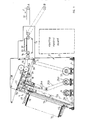
- a vertical signature stacker comprising: - a stacker framework 2; - a belt-driven conveyance path for the signatures delivered by a rotary press; - a separator plate 17 designed to interrupt the flow of signatures and form the initial part of each stack 16; - translation guides 26 and driving units 26c designed to raise and lower the separator plate 17; - a fork 8 onto which the bundles 16 delivered by the separator plate are placed, said fork being equipped with translation guides 7,7a,7b and with driving units designed to raise and lower same; - a sliding wall 14 for lowering the stacks 16 and a stack-supporting wall 15, both of which are made up of a number of rollers; wherein the separator plate 17 is designed to rest on a sliding frame 19 within the framework 2 of the stacker, said sliding frame being supported by a powered cursor 18 through a floating connection whereby the frame may be tilted up and down, said frame
- the sliding frame 19 of the separator plate 17 comprises two slide bars 21 featuring a cursor 18 in the form of two sleeves 22 connected to each other by a plate-supporting cross member 23, and said frame 19 is furthermore connected to a cylinder-ram unit 24 driving the plate 17 back and forth, the piston rod of said unit 24 being connected to said cursor 18.
- a cylinder-ram unit 28 is desirably interposed between the sliding frame 19 of the plate 17, hinged through 27 onto the plate-raising and lowering cursor 25, and said cursor 25, said unit 28 being designed to control the vertical tilting motion of said plate-supporting sliding frame 19.
- the separator plate 17 when retracted, is entirely housed in the body of the stacker, i.e. does not project therefrom.
- the translation guides 26 designed to control the upward and downward motion of the separator plate 17 comprise two channel sections housing the sliding cursor 25 which in turn supports the aforementioned frame 19, said cursor 25 being driven by means of lateral chains 26a provided with gears at their respective ends and in turn driven by means of other chains running within said channel sections and powered by an independent, preferably D.C., reversing electric motor.
- the lateral chains 7b controlling the motion of the fork 8 are driven by an independent, desirably D.C., reversing electric motor.
- the jogging 33, pressing 34 and flow-interrupting units are housed within rear side panels 5, fitted onto the sides 3 of the stacker, said rear panels 5 defining a housing for the electric control board of the stacker.
- the path 32 defined by the signature-conveying belts in the rear side panels 5 is desirably horizontal.
- the rear portion of said projecting side panels 5 features a vertically tilting connection path 31, the inclination of which may be adjusted depending on the relative height of the rotary press outlet.
- the motor 9 which controls the quick descent of the stack co-operates with a known electric component, through which the stroke of the fork 8 may be interrupted temporarily, in order to enable the operator to place the upper endboard onto the stack 16.
- the operation of the stacker may be checked from a more comfortable central position, and the separator plate is always within reach even when in its upper limit stop position. This enables the operator to perform all the necessary operations, such as the adjustment and line-up of the top-end positioners, both more quickly and more accurately.
- the separator plate is disposed inside the stacker in order to prevent accidental injury, hence the operator may perform all the relevant functions with a higher degree of safety.
- Both the height of the stacker and the length of the horizontal signature-conveying belts have been reduced considerably; as a result, the stacker according to the invention features limited overall dimensions. This, in turn, implies significant structural and functional advantages.
- the side panels of the stacker may be obtained directly from steel plates produced in standard sizes and, therefore, with a limited amount of off-cuts.
- the side panels provided to support the signature-conveying path may be designed as projecting members, to be mounted onto the framework of the stacker.
- the total cost of the stcker is further reduced by eliminating the pneumatic cylinder-ram units.
- the adoption of independent, reversing electric motors for the separator plate and the fork simplifies the various steps involved in the operating cycle and, as regards the fork-driving motor, ensures greater safety when lowering the stacks because braking is effected by the electric motor itself rather than by a pneumatic unit.
- an electric motor is undoubtedly the most effective means to readily interrupt the quick downstroke of the fork and, therefore, bring it to a halt.
- the signature conveyance path is made considerably shorter as the outlet through which the signatures are delivered and placed onto the separator plate is set at approximately the same height as the outlet of the traditional rotary presses. This offers an additional advantage, in that the conveyance path is at all times level, whereas conventional vertical stackers include a steeply-sloping section which, as noted earlier, affects the signatures undesirably.
- the stackers designed in accordance with this invention are easy to construct, and the type of equipment used to control the motion of translation of the separator plate is traditional and extremely dependable.
- Said stacker 1 comprises a framwork 2 featuring two side panels 3, which are joined to each other by a bedplate 4 and by a number of crosspieces (not illustrated herein).
- the framework 2 further comprises rear side panels 5, which are mounted as projecting members onto side panels 3, e.g. by means of screws 6.
- Said rear side panels 5 are designed to support the signature-conveying path (not shown), in correspondence with the relevant signature-handling components, as described more specifically hereinafter.
- the translation guides of fork 8 are marked 7.
- Said guides may be constructed in accordance with a conventional design, e.g. comprising channel sections 7a housing lateral chains 7b supporting a cursor 8a, fork 8 resting on said cursor 8a.
- the upward and downward motion of fork 8 is effected by means of an independent reversing electric motor 9, desirably a D.C. motor, which, through gearing 10, drives the bottom geared wheels 11 of said lateral traversing chains 7b.
- the sliding wall through which the stacks 16 are lowered and the bottom wall supporting said stacks are marked 14 and 15 respectively, both walls being made up of a set of adjacent rollers.
- roller board 14 is positioned in such a way as to form a 20° angle with the vertical.
- the separator plate which is only sketched out in the drawings, is indicated at 17.
- the plate is supported within the framework 2 of the stacker and is secured to the cursor 18 of the plate sliding frame marked 19.
- Said frame may comprise, for instance, an actual frame-like structure 20 and two slide bars 21.
- Said cursor 18 is made up of two sliding sleeves 22, running on bars 21 and connected to each other by a crosspiece 23 which in turn carries the separator plate 17, said plate being interchangeable in the preferred embodiment.
- Cursor 18 is connected to the free end of the piston rod 24a (no detailed view thereof being provided in the drawings) of the cylinder-ram unit 24 controlling the forward and reverse motion of separator plate 17 and fixed to said sliding frame 19.
- the stroke of the piston rod 24a is desirably adjustable as a function of the signatures that are to be treated.
- the sliding frame 19 is connected to cursor 25 running on guides 26 fitted inside said framework 2 and specially designed to control the upstrokes and downstrokes of the separator plate 17.
- Said guides 26 may be channel-shaped, like the guides 7a referred to earlier herein, and be designed in such as way as to house the chains 26a supporting cursor 25 and driven, through an intervening chain 26b, by a reversing, preferably D.C., electric motor 26c.
- cursor 25 may feature outer guide sleeves running on corresponding guide bars (not shown herein).
- the connection between said cursor 25 and said slide frame 19 is effected by means of two coaxial hinge pins 27.
- the relevant drawing also features a cylinder-ram unit 28 interposed between cursor 25 and slide frame 19, said unit 28 being hinged onto cursor 25 through 29 and onto slide frame 19 through 30.
- the slide frame 19, hence the separator plate 17, are desirably hinged onto said cursor 25, in order to enable said plate 17 to tilt upwards during its forward motion and to tilt downwards when disposed, at some distance, above the stack placed on the descending fork.
- Said compound motion is designed to avoid any possible impact of the tip of the separator plate against the upper part of the stack which has previously been placed onto the fork 8.
- Said motion may be achieved by combining the motions of the two cylinder-ram units 24 and 28, or, alternatively, through the interposition of a positioning cam co-operating with separator plate 17. The profile and exact location of said cam are to be determined in accordance with one's specific requirements.
- the desired motion of translation of the separator plate may also be achieved through a driving cam alone, namely without employing the cylinder-ram unit 28; in this case, however, it would be more difficult to attain the required degree of accuracy in the repetition of the compound movements.
- the drawings readily show that when the separator plate is in its upper limit stop position, i.e. the position wherein it is ready to perform the interruption of the flow of signatures, the plate itself is housed entirely within the body of the stacker; the dotted lines refer to the plate in its tilted-up position, namely the position wherein the plate is ready to start a new stack.
- the signature conveyance path is roughly horizontal and, in this particulr instance, made up of a number of conveyor belts 31; the path itself can be tilted up or down, position A corresponding to the outlet of the higher rotary presses, and position B being roughly level with the outlet of the lower rotary presses.
- the section of the signature-conveying path located inside the stacker is marked 32, said section featuring a jogging unit 33, a pressing unit 34 as well as a third unit (only sketched out in the drawing) specially designed to interrupt the flow of signatures and thereby enable the separator plate 17 to perform its function effectively.
- Section 32 of the conveyance path is followed by section 35, which leads to the signature delivery outlet 36.
- Section 35 is slightly slanted because it must be at right angles with roller board 14.
- the drawing clearly shows that the signature path is essentially horizontal and does not feature the steeply-sloping section which is typically found in conventional vertical stackers equipped with an outwardly-projecting separator plate.
- the signature-conveying path is driven by a separate motor 37, of a known type.
- the unit defining the upper signature-conveying path is marked 38, and the relevant driving motor is indicated at 39.
- the various steps involved in the operating cycle - preliminary stacking, translation of the preliminary stack from the separator plate to the fork, completion of the stack and quick descent of the stack onto the supporting roller board - are performed in the same way as they normally are in conventional vertical stackers featuring an outwardly-projecting separator plate.
- the design features an essentially horizontal signature conveyance path while offering simple, highly reliable means to interrupt the quick descent of the stack-carrying fork so that the upper endboards may be placed automatically onto the finished stacks during the downward translation thereof.
- construction costs are reduced considerably, and the operations required in order to stretch the conveyor belts are simplified. As a result of lesser wear, belt rupture is less likely to occur.
- stacker operation is more reliable.
- a housing for the relevant electric switchboard is conveniently defined in the area located below the rear panels of the stacker. Practically all of the components may be replaced with other technically and/or functionally equivalent ones, without exceeding the scope of this invention.
- the design of the slide frame, of the relevant vertical guides, or of the separator plate-supporting member may be changed or modified without exceeding the boundaries defining the scope of the invention.
Landscapes
- Engineering & Computer Science (AREA)
- Mechanical Engineering (AREA)
- Pile Receivers (AREA)
- Forming Counted Batches (AREA)
- Heterocyclic Carbon Compounds Containing A Hetero Ring Having Oxygen Or Sulfur (AREA)
Applications Claiming Priority (2)
| Application Number | Priority Date | Filing Date | Title |
|---|---|---|---|
| IT2029986 | 1986-05-02 | ||
| IT20299/86A IT1204332B (it) | 1986-05-02 | 1986-05-02 | Impilatore di segnature verticali perfezionato |
Publications (2)
| Publication Number | Publication Date |
|---|---|
| EP0243769A2 true EP0243769A2 (de) | 1987-11-04 |
| EP0243769A3 EP0243769A3 (de) | 1989-07-26 |
Family
ID=11165530
Family Applications (1)
| Application Number | Title | Priority Date | Filing Date |
|---|---|---|---|
| EP87105431A Withdrawn EP0243769A3 (de) | 1986-05-02 | 1987-04-13 | Vorrichtung zum Stapeln von Signaturen |
Country Status (5)
| Country | Link |
|---|---|
| US (1) | US4897017A (de) |
| EP (1) | EP0243769A3 (de) |
| DK (1) | DK168066B1 (de) |
| IT (1) | IT1204332B (de) |
| NO (1) | NO163364C (de) |
Cited By (1)
| Publication number | Priority date | Publication date | Assignee | Title |
|---|---|---|---|---|
| DE10115251A1 (de) * | 2001-03-28 | 2002-10-10 | Gaemmerler Ag | Stangenbildner |
Families Citing this family (7)
| Publication number | Priority date | Publication date | Assignee | Title |
|---|---|---|---|---|
| IT1236921B (it) * | 1989-12-22 | 1993-04-26 | Civiemme Srl | Impilatore verticale automatico per segnature. |
| NO901737L (no) * | 1990-04-19 | 1991-10-21 | Norlito Maskin As | Pakkemaskin for blader (stakker). |
| US5421662A (en) * | 1994-06-22 | 1995-06-06 | R. R. Donnelley & Sons Company | Stabilization system for the printing of signatures |
| JP3455093B2 (ja) * | 1997-11-14 | 2003-10-06 | シャープ株式会社 | シート後処理装置 |
| DE19925065A1 (de) * | 1999-06-01 | 2000-12-07 | Heidelberger Druckmasch Ag | Verfahren zum Betreiben einer Bogen verarbeitenden Maschine |
| US6302638B1 (en) | 1999-11-12 | 2001-10-16 | Dorner Mfg. Corp. | Combined pushing mechanism and dead plate for stacker accumulation tray |
| US6296437B1 (en) | 1999-11-12 | 2001-10-02 | Dorner Mfg. Corp. | Discharge stacking station for sortation conveying system |
Family Cites Families (10)
| Publication number | Priority date | Publication date | Assignee | Title |
|---|---|---|---|---|
| US3279792A (en) * | 1963-11-18 | 1966-10-18 | Donnelley & Sons Co | Stacker for paper sheets or signatures |
| GB1472248A (en) * | 1974-06-26 | 1977-05-04 | Linotype Machinery Ltd | Stacking machines |
| US3969993A (en) * | 1975-07-07 | 1976-07-20 | Stobb, Inc. | Separator for a sheet stacker |
| DE7618803U1 (de) * | 1976-06-14 | 1976-11-11 | Stahl Gmbh & Co Maschinenfabrik, 7140 Ludwigsburg | Bogenauslage fuer papierverarbeitungsmaschinen |
| ES474384A1 (es) * | 1977-11-28 | 1979-04-16 | Mohn Ohg Reinhard | Procedimiento y dispositivo para producir un mazo atado de pliegos de papel. |
| CH633761A5 (fr) * | 1979-10-09 | 1982-12-31 | Bobst Sa | Dispositif pour empiler des objets plats, notamment des decoupes de boites pliantes. |
| IT1151425B (it) * | 1982-06-02 | 1986-12-17 | Civiemme Srl | Dispositivo di supproto e guida della penna retrattile in impilatori |
| IT1212986B (it) * | 1983-06-14 | 1989-12-07 | Ilte Ind Libraria Tipografica | Macchina per l impilaggio di segnature |
| US4538511A (en) * | 1983-08-24 | 1985-09-03 | Harris Graphics Corporation | Signature handling apparatus |
| US4541763A (en) * | 1983-07-28 | 1985-09-17 | Harris Graphics Corporation | Apparatus for forming a stack of signatures |
-
1986
- 1986-05-02 IT IT20299/86A patent/IT1204332B/it active
-
1987
- 1987-04-13 EP EP87105431A patent/EP0243769A3/de not_active Withdrawn
- 1987-04-21 NO NO871639A patent/NO163364C/no not_active IP Right Cessation
- 1987-04-30 US US07/044,441 patent/US4897017A/en not_active Expired - Lifetime
- 1987-05-01 DK DK222287A patent/DK168066B1/da not_active IP Right Cessation
Cited By (2)
| Publication number | Priority date | Publication date | Assignee | Title |
|---|---|---|---|---|
| DE10115251A1 (de) * | 2001-03-28 | 2002-10-10 | Gaemmerler Ag | Stangenbildner |
| US6889973B2 (en) | 2001-03-28 | 2005-05-10 | Gammerler Ag | Vertical log stacker |
Also Published As
| Publication number | Publication date |
|---|---|
| IT1204332B (it) | 1989-03-01 |
| DK222287A (da) | 1987-11-03 |
| NO163364C (no) | 1990-05-16 |
| NO871639D0 (no) | 1987-04-21 |
| NO163364B (no) | 1990-02-05 |
| DK168066B1 (da) | 1994-01-31 |
| US4897017A (en) | 1990-01-30 |
| NO871639L (no) | 1987-11-03 |
| EP0243769A3 (de) | 1989-07-26 |
| DK222287D0 (da) | 1987-05-01 |
| IT8620299A0 (it) | 1986-05-02 |
Similar Documents
| Publication | Publication Date | Title |
|---|---|---|
| EP0243769A2 (de) | Vorrichtung zum Stapeln von Signaturen | |
| KR101237004B1 (ko) | 하급지형 골판지 자동급지기계 | |
| SU843724A3 (ru) | Устройство дл загрузки стеллажей | |
| US4431358A (en) | Apparatus for breaking up stacks of boards in power saws or the like | |
| US5096372A (en) | Paper feeding/piling apparatus for sheet-fed press | |
| KR101697329B1 (ko) | 양끝절단 포장 적재시스템의 정렬장치 및 그 부대장치 | |
| US20060196328A1 (en) | Loaf seam synchronization device for continuous loaf feed slicing machine | |
| CN210849668U (zh) | 一种自动管材切割系统 | |
| EP0215341A1 (de) | Vorrichtung zum Versehen von Bogenstapeln mit Endplatten und zum Transportieren dieser Stapel in Stapelvorrichtungen für Druckereien und dergleichen | |
| CN110614572A (zh) | 一种自动管材切割系统 | |
| US4010944A (en) | Blank feeding device having an adjustable and automatic positioning backstop means | |
| CN210848557U (zh) | 一种自动管材切割系统的进料机构 | |
| CN213352632U (zh) | 一种龙门裁断机 | |
| KR101697312B1 (ko) | 양끝절단 포장 적재장치 | |
| CN109248967B (zh) | 带叠料装置的冲压产品收集装置及收叠方法 | |
| JPH1071598A (ja) | 打抜型の交換・収納装置およびこれを備えた平盤打抜機 | |
| CN215625520U (zh) | 一种翻转装置及压板机 | |
| US5738485A (en) | Pallet handling apparatus | |
| JPS601933Y2 (ja) | 長尺棒状材の切断装置 | |
| CN106801112A (zh) | 一种横纵式多层牛皮切割机 | |
| JPH06179530A (ja) | 枚葉紙加工機の給紙装置における安全装置 | |
| JPH061333U (ja) | 棒材供給機 | |
| KR200195248Y1 (ko) | 코일적재용 패드 공급장치 | |
| CN214520788U (zh) | 一种上料装置及贴皮设备 | |
| CN210849667U (zh) | 一种自动管材切割系统的卸料机构 |
Legal Events
| Date | Code | Title | Description |
|---|---|---|---|
| PUAI | Public reference made under article 153(3) epc to a published international application that has entered the european phase |
Free format text: ORIGINAL CODE: 0009012 |
|
| AK | Designated contracting states |
Kind code of ref document: A2 Designated state(s): AT BE CH DE ES FR GB GR IT LI LU NL SE |
|
| PUAL | Search report despatched |
Free format text: ORIGINAL CODE: 0009013 |
|
| AK | Designated contracting states |
Kind code of ref document: A3 Designated state(s): AT BE CH DE ES FR GB GR IT LI LU NL SE |
|
| 17P | Request for examination filed |
Effective date: 19900126 |
|
| 17Q | First examination report despatched |
Effective date: 19910625 |
|
| STAA | Information on the status of an ep patent application or granted ep patent |
Free format text: STATUS: THE APPLICATION HAS BEEN WITHDRAWN |
|
| 18W | Application withdrawn |
Withdrawal date: 19920602 |
|
| RIN1 | Information on inventor provided before grant (corrected) |
Inventor name: CASTIGLIONI, ANTONIO |