EP0243328A2 - Réceptacles de cosmétique en forme de bâtonnet, tels que rouge à lèvre ou analogue, et procédé de réalisation du bâtonnet et du contrôle visuel de la qualité - Google Patents
Réceptacles de cosmétique en forme de bâtonnet, tels que rouge à lèvre ou analogue, et procédé de réalisation du bâtonnet et du contrôle visuel de la qualité Download PDFInfo
- Publication number
- EP0243328A2 EP0243328A2 EP87830153A EP87830153A EP0243328A2 EP 0243328 A2 EP0243328 A2 EP 0243328A2 EP 87830153 A EP87830153 A EP 87830153A EP 87830153 A EP87830153 A EP 87830153A EP 0243328 A2 EP0243328 A2 EP 0243328A2
- Authority
- EP
- European Patent Office
- Prior art keywords
- wall
- pin
- container
- shell
- base body
- Prior art date
- Legal status (The legal status is an assumption and is not a legal conclusion. Google has not performed a legal analysis and makes no representation as to the accuracy of the status listed.)
- Granted
Links
Images

Classifications
-
- A—HUMAN NECESSITIES
- A45—HAND OR TRAVELLING ARTICLES
- A45D—HAIRDRESSING OR SHAVING EQUIPMENT; EQUIPMENT FOR COSMETICS OR COSMETIC TREATMENTS, e.g. FOR MANICURING OR PEDICURING
- A45D40/00—Casings or accessories specially adapted for storing or handling solid or pasty toiletry or cosmetic substances, e.g. shaving soaps or lipsticks
- A45D40/06—Casings wherein movement of the lipstick or like solid is a screwing movement
-
- Y—GENERAL TAGGING OF NEW TECHNOLOGICAL DEVELOPMENTS; GENERAL TAGGING OF CROSS-SECTIONAL TECHNOLOGIES SPANNING OVER SEVERAL SECTIONS OF THE IPC; TECHNICAL SUBJECTS COVERED BY FORMER USPC CROSS-REFERENCE ART COLLECTIONS [XRACs] AND DIGESTS
- Y10—TECHNICAL SUBJECTS COVERED BY FORMER USPC
- Y10S—TECHNICAL SUBJECTS COVERED BY FORMER USPC CROSS-REFERENCE ART COLLECTIONS [XRACs] AND DIGESTS
- Y10S425/00—Plastic article or earthenware shaping or treating: apparatus
- Y10S425/032—Lipstick
Definitions
- Containers for cosmetic cosmetics in the form of a stick are known, in which the stick is actuated from a position which is completely retracted inside the container when not in use and into a position which protrudes from the edge of the free end of this container when it is used.
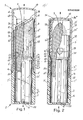
- the two parts 2 'and 2 are separated by a peripheral outer shoulder 22 on which the free end 14 of the cap 1 comes to rest in the closed position.
- Means are also provided which are suitable for a tight closing coupling between the inner surface 15 'of the lower part of the cap 1' and the to accomplish outer surface 21 "of the upper part of the outer base body 2", etc. by means of at least one preferably thread-like, radial, circumferential projection 25 located on one of the two coupling surfaces, which presses elastically or respectively against the other and thereby causes a circumferential elastic friction, at least one of the two walls, 21 "or 15 ', being made elastic by reducing the thickness due to the plastic materials used, or by integrally coupling an annular additional element 16 made of a material which is sufficiently more elastic than the materials used for the two components of the walls 21 "and 15 ', which is a better circumferential in the day to cause elastic friction.
- the circumferential thread-like projection 25 is located on the outer wall 21 "of the upper part of the outer base body 2", while the reduction in thickness 13 is accomplished by means of a circumferential inner step 12 which the upper inner wall 15 "and separates the lower inner wall 15 'at the upper part of the cap 1', where further on the left on the inner wall 15 'of the lower part of this cap 1' an elastic ring element 16 is added.
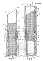
- the improvements of the present invention also pull on the intermediate body 3 for protection and for guiding the pin 9, which is designed as a tubular sleeve with two open ends, is formed in one piece and consists of two parts 3 'and 3 ".
- the adjacent upper part 3 protrudes remarkably from the upper end of the outer body 2 and has a length preferably and substantially at least approximately equal to the length of the pin projecting from the edge of the tub, ie the shell.
- the shells be it the inner wall 36 it the outer wall 31 "to protect the pin 9 of this upper part 3" has a substantially constant cross section without sudden changes in thickness 33 over the entire length, without grooves and / or slots, such that when the said intermediate body 3 is made of matt material , made of transparent material, or made transparent, this upper protective part 3 "makes it possible to have a maximum and complete view at every point of the pin 9, in particular in order to reduce both the color and any shaping errors 53 of the pin (FIG 1) to be able to be recognized directly in the protected position inside the container.
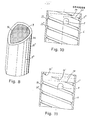
- this part 3 "of the intermediate body can be designed as a tubular sleeve and have any cross-section of the outer wall and the inner wall, as can the associated cosmetic pin 9 , in addition to the usual round cut and in particular cross section with three flat or curved sides (Fig . 8), as not shown in the figures, also a cross section with several sides or an elliptical cross section, and the free upper end of the upper part of the intermediate body 3 "can be made with a facade, which is determined by the crossing of the pipe sleeve-like wall, except with a horizontal transverse plane, upper end 34 (FIGS.
- the containers for cosmetics in the form of a stick are formed from four basic parts, means are required which are suitable for the intermediate body 3 and the outer base body 2 in axial solidarity, i.e. one-piece, but mutually rotatable
- a thread-like projection 27 is provided a little below the upper end and adjacent to this (FIGS. 1 and others) in the thickness 23, preferably with a sawtooth-like profile, over a groove 28, or (FIGS. 11) Double projections 27 ', which are slightly apart, annular, radial, circumferential and interrupted and are crossed by at least one helical groove, 6 1 or 6 ", or two helical grooves, 6, such as hollowed out surfaces 26 or surfaces 26 'to form, which consist of slight ridges that protrude inward on the cylindrical inner wall.
- the circumferential, radial annular groove 28 which is located on the surface of the inner wall, instead of having a shape complementary to the profile of the sawtooth-like projection 27 (FIGS. 1,4,5 , 6, left) compared to the latter, a further furrowed profile, in order to form an inner ring step 29 on the wall of a certain height below the ring projection 27 (FIGS. 1, 3, 6, right), so that an elastic joint for the upper part 2 "with a reduced thickness 23 and the tearing operation is facilitated.
- an additional element 30 can be placed over it to cover the upper part 2 "of the outer base body 2, such as a metallic facet, a tubular sleeve, the inner wall of which has an upper end with an inwardly directed edge 26 "(FIGS.
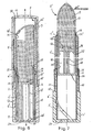
- a capsule 5 rests with elastic pressure on its entire end 34 over the entire circumference of the rim, in order to provide a tight seal on this upper end 34 to cause when the upper end 43 of the pin carrier shell 4 with elastic pressure the entire circumference of which rests on the inner wall 36 of the intermediate body and is positioned at a height above the axial or helical groove 7, 7 ', in order to bring about a seal between this pin carrier shell 4 and the inner wall 36 of the upper part 3 "of this intermediate body 3 , so that this container can form a closed hollow vessel in its interior, which is suitable for determining a die shape of the pin 9.
- the capsule 5 rests on the one hand on the inner wall of the summit wall 10 of the cap 1, possibly with a support 51, while on the other hand it rests with elastic pressure on the inner surface 36 (FIG. 3) or outer surface 31 "(FIGS.
- the pin forming surface may be such the top in order except as to the axis horizontal transverse surface as a plane surface 50 or inclined curved surface 50 'of any angle to be formed, preferably as a flat surface ( Figures 3 and 5) or convex curved surface (Fig. 6) inclined by 30 ° with respect to the horizontal transverse plane with respect to the axis.
- the container is reversed, so that the still liquid cosmetic mask 9 'is covered by waste from the lower part 4' of the container Shell 4 can move through the opening 42 on the support plane 41 of the bottom of the pin in the upper, closed, hollow vessel, which is suitable for determining the die of the pin; in both cases, this upper, closed, hollow vessel, which determines the die of the pin, is formed from the inner wall by the flat surface 50 or curved surface 50 'of the sealing capsule 5, which is inclined at any angle with respect to the horizontal plane and directed towards the pin 36 of the upper part 3 "of the intermediate body 3 of any cross-section and of the inner wall of the upper part 4" of the pin carrier shell 4, delimited by the open surface 42 of the support plane 41 of the pin 9.
- the pin carrier shell 4 is designed as a tubular sleeve, with an open upper end 43 and an end completely closed by a bottom wall 40 and 40 ', preferably approximately equal in height to the height of the inner wall of the outer base body 2, and at a certain height has a transverse bearing surface 41 of the pin, which divides the shell 4 into two parts (a lower 4 'and an upper 4 ").
- the transverse bearing surface 41 is on the inside in the thickness of the shell of the tubular wall provided (not explained in the drawings), so that the upper part 4 "a larger cross Surface has as the lower part 4 ', in such a way to determine a circumferential support shoulder of the bottom of the pin.
- the transverse contact surface is provided on the top wall 41 'of an axial sleeve 47 of any cross section (FIG. 6), with smaller dimensions compared to the cross section of the sleeve of the shell 4, the open opposite end 48 of which is the annular bottom wall 40 'tightly closes the shell, where this annular bottom wall 40' has a surface complementary to the open transverse surface 48 of the sleeve.
- the transverse bearing surface can be provided on a ring 41 "or on a ring of transverse ribs which protrude outwards and are fixed at the open upper end of an axial ring sleeve 47 of any cross section which has at least one along a generating line Has slot 49, the open lower opposite end is fixed to the closed wall of the bottom wall 40 of the shell 4.
- the lower part of the tub ie the shell, 4 '
- the lower part of the tub can be located 41, 41', 41 "below the support plane of the bottom of the pin when this cosmetic mass 9 'from the upper end of the container 34, 34', 34 "is introduced, with cap 1 and cap sel5 or 5 'switched off (as illustrated in Figure 6 left), serve as a closed, hollow container 45 for a preliminary collection of the liquid cosmetic product 9'.
- the container is inverted, so that the still liquid cosmetic mass 9 'can be displaced by waste from the lower part of the shell 4, which acts as a preliminary collecting vessel 45, via the opening 42 at the support plane 41' or 41 "of the bottom of the stick into the upper, closed, hollow vessel , the die of the pin 9 is to be determined soft.
- this upper, closed, hollow vessel which determines the die of the pin is formed by the sole hollow inner surface 50 "of the capsule 5 'in one case (FIG. 7) or by the flat surface 50 or any inclined curved surface 50 'with respect to the horizontal plane of the closure capsule 5 directed towards the pin and from the inner wall of the upper part 3 "of the intermediate body 3 of any cross-section in the other case (FIG. 6), and both from the inner wall of the upper part 4" of the pin holder shell 4, which is determined by the open surface 42 of the support plane 41 'or 41 "of the pin.
- the means which are suitable for shaping the pin 9 in the container and in a position completely outside of its upper end 34, 34 ', 34 "(FIG. 7) are characterized in that the pin carrier shell 4 is at least as long as that Pin 9, this cantilever, with the upper end 43 and lower end closed by a bottom surface 40 ', 40, or at least temporarily tightly closed between the lower end 44 of the shell 4 with 2 solidary ring surfaces 24 on the bottom of the inner wall 20 of the outer base body, with a open transverse support surface 41, 41 ', 41 ", as described above in a ring-shaped 41, ring-shaped in the thickness of the jacket of the tubular wall, in a ring-shaped 41” or place-like manner 41' carried by tubular sleeves 47, open or closed, in solidarity with the closed bottom surface 40 , the upper part 4 "of this pin carrier shell 4 has the function of retaining the bottom of the pin, while the lower part 4 'the radio tion of a preliminary receptacle 45 of product 9 ', this t
- the capsule 5 'acting as a die of the pin 9 can now be removed and the closure cap 1 of the container can be put on.
- Means are also provided which are suitable for anchoring the bottom surface of the pin, which are characterized in that the open transverse bearing surface 41, 41 "of the bottom of the pin, which forms the two parts 4" and 4 '(upper and lower) of the shell 4 separates, has undercut surfaces 54 anchored in the body of the pin 9 if, during the casting operation of the liquid product 9 and the subsequent solidification, the product remains at a height partially below the contact surface of the pin, etc. in the upper part of the lower part of the tub, i.e. the Bowl .
- Means are also provided which are suitable for causing a lower end stop of the movement of the pin carrier shell 4 (FIGS. 4, 5), especially since the wall corresponding to the lower end 44 of the shell 4 is made elastic by reducing the thickness 46 in a completely retracted position at one ring-shaped inner bear surface 24 all around, ring-shaped, elastic elastic ben, the latter being positioned in a protruding or protruding manner on the bottom 20 of the outer base body 2, in such a way as to bring about a frictional connection between the two bodies in the vicinity of the end stop position.
- Means are also provided which are suitable for effecting the exit and retraction movement of the pin carrier shell by providing the outer wall of this pin carrier shell 4 with at least one rigid nose 8 and at least one elastic nose 8 '(FIG. 9).
- the rigid nose 8 is positioned on an inelastic wall part, in order not to significantly reduce the distance from the axis due to a certain pressure, while the elastic nose 8 'is positioned on an elastic wall part, in such a way that due to a certain pressure Noticeably reduce the distance from the axis.
- Both lugs 8 and 8 ' are displaceable via at least one guide slot 7, 7' of the intermediate body 3 in the groove 6 'or 6 "or in the corresponding grooves 6, or in an alternative solution not shown in the figures, the elastic lug 8' displaceable via at least one guide slot 7, 7 'of the intermediate body 3 in the inner wall of the outer base body 2, the rigid nose 8 not being in contact with the bottom of this groove 6, 6', 6 ", while the elastic groove 8 'with elastic Friction on this Bo the groove 6,6 ', 6 "is in contact.
- Means are also provided which are suitable for determining the control movement of the pin carrier shell, the lug 8 running on the outer wall of this pin carrier shell 4 via at least one helical slot 7 'which runs along a generatrix on the wall of the lower part 3' of the intermediate body 3 is worked out, and in at least one helical groove 6 ', 6 ", which is worked out on the cylindrical inner wall of the outer base body 2 (Fig.
- an axial distance A is provided, in such a way as to bring about a safety margin so that the pin is in contact with this Cipfelwan due to unintentional axial movements. 10 of the cap can not deform.
- the cap 1, with any internal and external cross section, with or without annular circumferential steps on the inner wall 12 or on the outer wall be made of matt materials, and be provided on their outer jacket with at least one opening, (Fig. 3), eyelet 10 of any geometric or decorative shape, or of matted transparent material, which is masked by a cladding 18, which cladding 18 may be a metallic facet, a rolled strip (FIG. 1), an electroplating, a screen printing or similar process, such as to have transparent openings, and these transparent zones Eyelets 19 of any geometric or decorative shape or ring-band-like parts 17 of any shape and in any position.
- the contact surface 41, 41 ', 41 "of the bottom of the pin (FIGS. 1 to 7), closed or opened, is spaced a certain height from the lower end 44, with an open bottom or with closed bottom 40 of the pin carrier shell 4, characterized in that this transverse support surface 41, 41 ', 41 "is positioned in correspondence, or in the vicinity, below or above, with the circumferential outer shoulder 22, which separates the two parts 2' and 2" of the outer base body 2, where there the open end 14 of the cap comes to rest.
- means are provided which are suitable for checking the quality and the size of the bottom surface of the pin when the outer base body 2 is made of transparent material, so that it is possible to see through it through the guide slot 7 or 7 'of the lower one Part 3 'of the intermediate body. pers 3, if the latter is matt, the wall part of the pin carrier shell 4, and if the latter is transparent, also the bottom surface part of the pin, or alternatively, if the intermediate part 3 is transparent, the entire bottom part of the pin 9, etc.
Landscapes
- Closures For Containers (AREA)
- Containers And Packaging Bodies Having A Special Means To Remove Contents (AREA)
- Cosmetics (AREA)
Applications Claiming Priority (2)
| Application Number | Priority Date | Filing Date | Title |
|---|---|---|---|
| IT47927/86A IT1190531B (it) | 1986-04-24 | 1986-04-24 | Perfezionamenti negli astucci per cosmetici in stick,quali rossetti per labbra e simili,e relativi procedimenti per la formazione dello stick e il controllo visivo della qualita' |
| IT4792786 | 1986-04-24 |
Publications (3)
| Publication Number | Publication Date |
|---|---|
| EP0243328A2 true EP0243328A2 (fr) | 1987-10-28 |
| EP0243328A3 EP0243328A3 (en) | 1990-03-28 |
| EP0243328B1 EP0243328B1 (fr) | 1995-02-01 |
Family
ID=11263410
Family Applications (1)
| Application Number | Title | Priority Date | Filing Date |
|---|---|---|---|
| EP87830153A Expired - Lifetime EP0243328B1 (fr) | 1986-04-24 | 1987-04-22 | Réceptacles de cosmétique en forme de bâtonnet, tels que rouge à lèvre ou analogue, et procédé de réalisation du bâtonnet et du contrôle visuel de la qualité |
Country Status (5)
| Country | Link |
|---|---|
| US (1) | US4813801A (fr) |
| EP (1) | EP0243328B1 (fr) |
| DE (1) | DE3751030D1 (fr) |
| ES (1) | ES2068186T3 (fr) |
| IT (1) | IT1190531B (fr) |
Cited By (3)
| Publication number | Priority date | Publication date | Assignee | Title |
|---|---|---|---|---|
| US6109807A (en) * | 1996-09-03 | 2000-08-29 | Conception Et Moulage Au Service De L'industrie | Rotating cover, as used for a lipstick |
| IT201900005118A1 (it) * | 2019-04-04 | 2020-10-04 | Cosmei S R L | Prodotto cosmetico |
| CN112911966A (zh) * | 2018-07-27 | 2021-06-04 | 克丽丝汀迪奥香水化妆品公司 | 用于封装和施用化妆品的装置 |
Families Citing this family (30)
| Publication number | Priority date | Publication date | Assignee | Title |
|---|---|---|---|---|
| IT1231455B (it) * | 1989-04-03 | 1991-12-07 | Cardia Ennio E Ballarati Anna | Perfezionamenti al contenitore dispensatore di un prodotto solidificato a stick o fluido viscoso, particolarmente per cosmetica |
| KR910014077A (ko) * | 1990-01-19 | 1991-08-31 | 쉬지니 끌로드 | 동심원상으로 배치된 2개의 회전부재사이의 회전마찰장치 |
| FR2662921B1 (fr) * | 1990-06-07 | 1992-09-04 | Oreal | Procede d'obtention d'un dispositif pour appliquer un produit pateux, et dispositif ainsi obtenu. |
| US5183349A (en) * | 1990-11-15 | 1993-02-02 | Revlon Consumer Products Corporation | Lipstick dispenser formed with lipstick formulation |
| FR2670656B1 (fr) * | 1990-12-19 | 1993-11-05 | Oreal | Dispositif pour appliquer un produits pateux, notamment un produit cosmetique tel que du rouge a levres, et element tubulaire pour un tel dispositif. |
| US5197814A (en) * | 1991-06-24 | 1993-03-30 | Elizabeth Arden Co., Division Of Conopco, Inc. | Lipstick article |
| US5257704A (en) * | 1992-05-08 | 1993-11-02 | Revlon Consumer Products Corporation | Tamperproof lipstick seal |
| FR2704403B1 (fr) * | 1993-04-30 | 1998-12-24 | Scee | Rouge à lèvres échantillon à mécanisme élévateur simplifié permettant le coulage du raisin par le fond. |
| KR100238356B1 (ko) * | 1993-09-08 | 2000-01-15 | 호소에이사오 | 고상물공급용 카트리지형 공급케이스 |
| US5451113A (en) * | 1993-12-10 | 1995-09-19 | Maybelline Intermediate Corp. | Protective undercap and method |
| CN1066621C (zh) * | 1994-07-08 | 2001-06-06 | 株式会社希丹 | 化妆品容器 |
| JP2736039B2 (ja) * | 1994-08-25 | 1998-04-02 | 株式会社トキワ | 化粧料繰り出し容器 |
| WO1996012421A1 (fr) * | 1994-10-21 | 1996-05-02 | Societe De Conseils Et D'etudes Des Emballages (S.C.E.E.) | Etui applicateur pour produit solidifie |
| US5533823A (en) * | 1995-03-29 | 1996-07-09 | Rexam Cosmetic Packaging Inc. | Sealed cosmetic dispenser |
| US5860756A (en) * | 1996-11-22 | 1999-01-19 | Rexam Cosmetic Packaging, Inc. | Top-fill/bottom-fill cosmetic carrier for a lipstick container |
| US5829900A (en) * | 1997-05-06 | 1998-11-03 | Revlon Consumer Products Corp. | Container for cosmetic stick |
| US5829901A (en) * | 1997-05-06 | 1998-11-03 | Revlon Consumer Products Corp. | Container for cosmetic stick |
| US6033606A (en) * | 1997-07-07 | 2000-03-07 | Garza; Debra J. | Lipstick material recycling apparatus and method |
| US5971351A (en) | 1997-09-05 | 1999-10-26 | Swaab; Mary | Apparatus and method for blending and fabricating personalized lipstick |
| US6050540A (en) * | 1998-04-22 | 2000-04-18 | O'reilly; Betsy | Mold assembly for making customized lipstick colors |
| US5961007A (en) * | 1998-06-15 | 1999-10-05 | The Procter & Gamble Company | Dispensing package |
| JP3153992B2 (ja) * | 1998-06-25 | 2001-04-09 | 株式会社ヒダン | 化粧料容器 |
| AT5428U1 (de) * | 2000-09-20 | 2002-07-25 | Kores Holding Zug Ag | Klebestift |
| US6394270B1 (en) * | 2000-12-04 | 2002-05-28 | Ming Hsiung Liu | Structure of a lipstick case |
| US6561711B1 (en) * | 2002-05-21 | 2003-05-13 | Rexam Cosmetic Packaging, Inc. | Shade evident cosmetic package |
| USD468486S1 (en) | 2002-07-16 | 2003-01-07 | Chen-Hui Kuo | Lipstick case |
| US20130230347A1 (en) * | 2012-07-24 | 2013-09-05 | Rnd Group Llc | Slide type lipstick case structure |
| US10653228B2 (en) * | 2014-03-06 | 2020-05-19 | Patent Lab Sa | Method for manufacturing cosmetic product capsules, specifically lipsticks, and relating manufacturing machine |
| EP3878310B1 (fr) * | 2020-03-12 | 2024-05-01 | Corpack GmbH | Étui pour rouge à lèvres, brillant à lèvres, déodorant ou cosmétique |
| FR3135881A1 (fr) * | 2022-05-31 | 2023-12-01 | Albea Services | Dispositif d'application d'un raisin de produit cosmetique |
Family Cites Families (23)
| Publication number | Priority date | Publication date | Assignee | Title |
|---|---|---|---|---|
| US31021A (en) * | 1861-01-01 | Link shackle of chain cables | ||
| US1861552A (en) * | 1930-06-03 | 1932-06-07 | Benjamin F Savery | Jar and closure therefor |
| US2127350A (en) * | 1937-05-03 | 1938-08-16 | American Brass Co | Lipstick container |
| US2345315A (en) * | 1941-05-19 | 1944-03-28 | John W Anderson | Cosmetic stick expellant holder |
| US2797803A (en) * | 1955-04-15 | 1957-07-02 | Eyelet Specialty Co | Cosmetic container |
| US2855632A (en) * | 1957-02-11 | 1958-10-14 | Coty Inc | Method of filling cosmetic containers |
| US3315344A (en) * | 1962-06-06 | 1967-04-25 | Ejectoret Sa | Method for the production of cosmetic sticks, particularly lipsticks |
| US3317036A (en) * | 1964-05-21 | 1967-05-02 | Cherba Samuel | Lipstick holder |
| GB1163542A (en) * | 1965-08-31 | 1969-09-10 | Sebec | Lipstick containers |
| US3397027A (en) * | 1966-01-25 | 1968-08-13 | Valve Corp Of America | Stick-type applicator construction |
| US3511575A (en) * | 1967-07-27 | 1970-05-12 | Guild Molders | Lipstick case |
| US3817636A (en) * | 1972-09-07 | 1974-06-18 | Seidel Kg Geb | Cosmetic container |
| DE2629316A1 (de) * | 1976-06-30 | 1978-01-05 | Huck Fa H | Halter fuer lippenstifte o.dgl. |
| GB1552081A (en) * | 1977-04-04 | 1979-09-05 | Bridgeport Metal Goods Mfg Co | Lipstick container |
| US4579134A (en) * | 1977-09-08 | 1986-04-01 | The Bridgeport Metal Goods Manufacturing Co. | Lipstick container |
| GB2026983A (en) * | 1978-07-20 | 1980-02-13 | Cardia E | Cosmetics containers |
| US4147750A (en) * | 1978-07-24 | 1979-04-03 | Bristol-Myers Company | Method for eliminating shrinkage cavities in cast cosmetic sticks and similar products |
| US4208144A (en) * | 1979-04-03 | 1980-06-17 | Eyelet Specialty Co., Inc. | Cosmetic applicator with transparent container portion |
| USRE31021E (en) | 1979-04-03 | 1982-08-31 | Eyelet Specialty Co., Inc. | Cosmetic applicator with transparent container portion |
| US4417827A (en) * | 1980-05-20 | 1983-11-29 | Shiseido Company, Ltd. | Stick-type cosmetic applicator |
| US4323157A (en) * | 1980-10-17 | 1982-04-06 | Eyelet Specialty Co., Inc. | Bottom-fillable lipstick or the like container |
| IT8435894V0 (it) * | 1984-06-20 | 1984-06-20 | Cardia Ennio | Astuccio per cosmetici in stick, in particolare rossetti per labbra |
| IT8422533U1 (it) * | 1984-07-11 | 1986-01-11 | Terruzzi Ottavio | Contenitore per rossetto, pasta per labbra e/o deodorante. |
-
1986
- 1986-04-24 IT IT47927/86A patent/IT1190531B/it active
-
1987
- 1987-04-20 US US07/040,391 patent/US4813801A/en not_active Expired - Fee Related
- 1987-04-22 ES ES87830153T patent/ES2068186T3/es not_active Expired - Lifetime
- 1987-04-22 EP EP87830153A patent/EP0243328B1/fr not_active Expired - Lifetime
- 1987-04-22 DE DE3751030T patent/DE3751030D1/de not_active Expired - Fee Related
Cited By (3)
| Publication number | Priority date | Publication date | Assignee | Title |
|---|---|---|---|---|
| US6109807A (en) * | 1996-09-03 | 2000-08-29 | Conception Et Moulage Au Service De L'industrie | Rotating cover, as used for a lipstick |
| CN112911966A (zh) * | 2018-07-27 | 2021-06-04 | 克丽丝汀迪奥香水化妆品公司 | 用于封装和施用化妆品的装置 |
| IT201900005118A1 (it) * | 2019-04-04 | 2020-10-04 | Cosmei S R L | Prodotto cosmetico |
Also Published As
| Publication number | Publication date |
|---|---|
| IT8647927A0 (it) | 1986-04-24 |
| US4813801A (en) | 1989-03-21 |
| IT1190531B (it) | 1988-02-16 |
| EP0243328B1 (fr) | 1995-02-01 |
| IT8647927A1 (it) | 1987-10-24 |
| ES2068186T3 (es) | 1995-04-16 |
| EP0243328A3 (en) | 1990-03-28 |
| DE3751030D1 (de) | 1995-03-16 |
Similar Documents
| Publication | Publication Date | Title |
|---|---|---|
| EP0243328A2 (fr) | Réceptacles de cosmétique en forme de bâtonnet, tels que rouge à lèvre ou analogue, et procédé de réalisation du bâtonnet et du contrôle visuel de la qualité | |
| DE3586458T2 (de) | Spender. | |
| DE69612079T2 (de) | Stabförmiger kosmetikbehälter und stabförmige patrone für kosmetika | |
| DE69100886T2 (de) | Abnehmbare Kappe und Behälter versehen mit einem Garantieverschluss. | |
| DE69420536T2 (de) | Spender mit einem ersetzbaren halter für kosmetische mittel | |
| DE3327615C2 (de) | Zwei-Komponenten-Packung | |
| DE3437530A1 (de) | Behaelter mit abnehmbarer verschlussvorrichtung | |
| DE1206353B (de) | Behaelter aus Plastikmaterial und Verfahren zu seiner Herstellung | |
| DE69904171T2 (de) | Kunststoff-schraubkappe mit originalitäts-ring | |
| DE10297200T5 (de) | Einlagenloser Abdichtungs-Verschluss für Öffnungen | |
| EP0329640B1 (fr) | Fermeture inviolable pour un récipient et moule à injection pour la fabrication de la fermeture | |
| DE3513025A1 (de) | Schminkvorrichtung, insbesondere fuer wimpern | |
| DE3735909A1 (de) | Tropferflasche und verfahren zu ihrer herstellung | |
| DE69002483T2 (de) | Papierbehälter mit Öffnungsstöpsel. | |
| DE2532193A1 (de) | Sicherheits-schraubverschluss fuer behaelter | |
| DE60108343T2 (de) | Verschliessbare Ausgiesskappe | |
| DE1275448B (de) | Verschlussanordnung fuer Behaelter mit einem die Behaelteroeffnung umgebenden Hals und einer Verschlusskappe | |
| DE2063865A1 (de) | Zusammengesetzter Deckel für Behälter | |
| DE1942312C3 (de) | Durch axiales Aufpressen auf den Hals einer Flasche aufbringbare Verschlußkappe | |
| DE3711036A1 (de) | Verfahren zum einbringen eines stiftes in einen behaelter und einen derartigen behaelter | |
| DE60309663T2 (de) | "verfahren zur bereitstellung eines gelenk-garantieverschlusses, gelenk-garantieverschluss und behälter mit einem gelenk-garantieverschluss" | |
| DE69912621T2 (de) | Lippenstift und dessen herstellungsverfahren | |
| EP0079552A2 (fr) | Fermeture pour bouteilles, notamment pour bouteilles de champagne | |
| DE7813733U1 (de) | Lippenstift | |
| DE3886373T2 (de) | Behälter mit Tropfenrückfluss. |
Legal Events
| Date | Code | Title | Description |
|---|---|---|---|
| PUAI | Public reference made under article 153(3) epc to a published international application that has entered the european phase |
Free format text: ORIGINAL CODE: 0009012 |
|
| AK | Designated contracting states |
Kind code of ref document: A2 Designated state(s): DE ES FR GB |
|
| PUAL | Search report despatched |
Free format text: ORIGINAL CODE: 0009013 |
|
| AK | Designated contracting states |
Kind code of ref document: A3 Designated state(s): DE ES FR GB |
|
| 17P | Request for examination filed |
Effective date: 19900607 |
|
| 17Q | First examination report despatched |
Effective date: 19911220 |
|
| GRAA | (expected) grant |
Free format text: ORIGINAL CODE: 0009210 |
|
| AK | Designated contracting states |
Kind code of ref document: B1 Designated state(s): DE ES FR GB |
|
| REF | Corresponds to: |
Ref document number: 3751030 Country of ref document: DE Date of ref document: 19950316 |
|
| REG | Reference to a national code |
Ref country code: ES Ref legal event code: FG2A Ref document number: 2068186 Country of ref document: ES Kind code of ref document: T3 |
|
| GBT | Gb: translation of ep patent filed (gb section 77(6)(a)/1977) |
Effective date: 19950420 |
|
| ET | Fr: translation filed | ||
| PLBE | No opposition filed within time limit |
Free format text: ORIGINAL CODE: 0009261 |
|
| STAA | Information on the status of an ep patent application or granted ep patent |
Free format text: STATUS: NO OPPOSITION FILED WITHIN TIME LIMIT |
|
| 26N | No opposition filed | ||
| PGFP | Annual fee paid to national office [announced via postgrant information from national office to epo] |
Ref country code: DE Payment date: 19990525 Year of fee payment: 13 |
|
| PGFP | Annual fee paid to national office [announced via postgrant information from national office to epo] |
Ref country code: GB Payment date: 20000426 Year of fee payment: 14 |
|
| PG25 | Lapsed in a contracting state [announced via postgrant information from national office to epo] |
Ref country code: DE Free format text: LAPSE BECAUSE OF NON-PAYMENT OF DUE FEES Effective date: 20010201 |
|
| PG25 | Lapsed in a contracting state [announced via postgrant information from national office to epo] |
Ref country code: GB Free format text: LAPSE BECAUSE OF NON-PAYMENT OF DUE FEES Effective date: 20010422 |
|
| GBPC | Gb: european patent ceased through non-payment of renewal fee |
Effective date: 20010422 |
|
| PGFP | Annual fee paid to national office [announced via postgrant information from national office to epo] |
Ref country code: ES Payment date: 20060424 Year of fee payment: 20 |
|
| PGFP | Annual fee paid to national office [announced via postgrant information from national office to epo] |
Ref country code: FR Payment date: 20060426 Year of fee payment: 20 |
|
| PG25 | Lapsed in a contracting state [announced via postgrant information from national office to epo] |
Ref country code: ES Free format text: LAPSE BECAUSE OF EXPIRATION OF PROTECTION Effective date: 20070423 |
|
| REG | Reference to a national code |
Ref country code: ES Ref legal event code: FD2A Effective date: 20070423 |