EP0242679A2 - Dispositif de signalisation pour véhicule de combat, en particulier pour tank - Google Patents
Dispositif de signalisation pour véhicule de combat, en particulier pour tank Download PDFInfo
- Publication number
- EP0242679A2 EP0242679A2 EP87105019A EP87105019A EP0242679A2 EP 0242679 A2 EP0242679 A2 EP 0242679A2 EP 87105019 A EP87105019 A EP 87105019A EP 87105019 A EP87105019 A EP 87105019A EP 0242679 A2 EP0242679 A2 EP 0242679A2
- Authority
- EP
- European Patent Office
- Prior art keywords
- plate
- drive shaft
- rotatable
- combat
- signal
- Prior art date
- Legal status (The legal status is an assumption and is not a legal conclusion. Google has not performed a legal analysis and makes no representation as to the accuracy of the status listed.)
- Granted
Links
Images

Classifications
-
- F—MECHANICAL ENGINEERING; LIGHTING; HEATING; WEAPONS; BLASTING
- F41—WEAPONS
- F41H—ARMOUR; ARMOURED TURRETS; ARMOURED OR ARMED VEHICLES; MEANS OF ATTACK OR DEFENCE, e.g. CAMOUFLAGE, IN GENERAL
- F41H5/00—Armour; Armour plates
- F41H5/26—Peepholes; Windows; Loopholes
-
- B—PERFORMING OPERATIONS; TRANSPORTING
- B60—VEHICLES IN GENERAL
- B60Q—ARRANGEMENT OF SIGNALLING OR LIGHTING DEVICES, THE MOUNTING OR SUPPORTING THEREOF OR CIRCUITS THEREFOR, FOR VEHICLES IN GENERAL
- B60Q9/00—Arrangement or adaptation of signal devices not provided for in one of main groups B60Q1/00 - B60Q7/00, e.g. haptic signalling
-
- F—MECHANICAL ENGINEERING; LIGHTING; HEATING; WEAPONS; BLASTING
- F41—WEAPONS
- F41H—ARMOUR; ARMOURED TURRETS; ARMOURED OR ARMED VEHICLES; MEANS OF ATTACK OR DEFENCE, e.g. CAMOUFLAGE, IN GENERAL
- F41H7/00—Armoured or armed vehicles
- F41H7/02—Land vehicles with enclosing armour, e.g. tanks
-
- G—PHYSICS
- G08—SIGNALLING
- G08B—SIGNALLING OR CALLING SYSTEMS; ORDER TELEGRAPHS; ALARM SYSTEMS
- G08B5/00—Visible signalling systems, e.g. personal calling systems, remote indication of seats occupied
- G08B5/22—Visible signalling systems, e.g. personal calling systems, remote indication of seats occupied using electric transmission; using electromagnetic transmission
- G08B5/36—Visible signalling systems, e.g. personal calling systems, remote indication of seats occupied using electric transmission; using electromagnetic transmission using visible light sources
- G08B5/38—Visible signalling systems, e.g. personal calling systems, remote indication of seats occupied using electric transmission; using electromagnetic transmission using visible light sources using flashing light
Definitions
- the invention relates to a signal device for combat vehicles, in particular for battle tanks, with a flashing device which only emits signals in the thermal image spectrum.
- the above-mentioned older signaling device has a flashing device in which the radiating element can be covered by a motor-driven screen in predetermined directions and a predetermined rhythm.
- the radiating element itself is designed as a cylindrical body, on the inner surface of which a heating mat is arranged and in which an electric motor is arranged, ----------------------------------------------------------- which drives a circumferential diaphragm arranged outside the cylinder tube.
- the radiating element takes up a relatively large amount of space, which has a disadvantageous effect when the signaling device is removed from the combat vehicle and is to be accommodated, for example, inside the vehicle.
- particularly careful measures for thermal insulation between the heating mat and the electric motor arranged inside the heating mat must be provided for a radiating element of this construction.
- the object underlying the invention was to design a signal device of the type mentioned at the outset so that the radiating element takes up as little space as possible and the entire device can be stowed in the smallest possible space.
- the radiating element is particularly well adapted to the conditions which prevail in the case of radiation in the thermal image spectrum.
- the radiating element is a flat plate, which would not be readily possible, for example, with a flashing device which radiates in the range of visible light it is not necessary to provide an additional motorized diaphragm to cover the radiating element in a predetermined rhythm.
- the rotational movement of the radiating element itself means that radiation is emitted only in one direction perpendicular to the radiating surface, while hardly any radiation takes place in the plane of the radiating surface, that is to say in the direction of the narrow sides of the plate.
- the code to be provided is advantageously generated by an electrical control device, for example a programmable control device known per se, with the aid of which it can be programmed how many revolutions the plate should make and which pause lengths between the revolutions should occur.
- an electrical control device for example a programmable control device known per se, with the aid of which it can be programmed how many revolutions the plate should make and which pause lengths between the revolutions should occur.
- an aperture covering approximately half of the radiation area of the radiating element can be provided, which prevents a thermal image signal from being emitted in an undesired direction.
- This additional screen can be designed so that it can be folded up. In this way it is achieved that when the signal device is removed and disassembled, neither the radiating element nor the surrounding diaphragm take up much space.
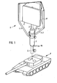
- the flashing device B of a signal device is arranged on a main battle tank P of conventional design, for example on the center of the turret, which signal device is connected via a connecting cable 19 to an electrical control device inside the turret.
- the flashing device B has a holding tube 3 which can be plugged onto a corresponding component on the main battle tank P by means of an attachment piece 3.1 and can be fixed by means of a screw connection 16.
- An electric motor 5 is arranged within the holding tube 3, the output shaft 6 of which is fixedly connected to an axially guided through the holding tube 3 drive shaft 2, which is mounted within the holding tube 3 via rotary bearings 8 and is guided out of the holding tube 3 at the upper end thereof.
- a flat plate 1 is arranged as a radiating element, which, as can be seen from FIG. 2, is made up of several layers.
- An insulating layer 11 is initially arranged on a base plate 12, on which an electric heating mat 9 is placed.
- a good radiating protective layer 10 is placed on the outside of the heating mat 9.
- the radiating surface is thus parallel to the drive shaft 2 and the radiation takes place perpendicular to the central axis of this drive shaft.
- the lead 9.1 to the heating mat 9 is passed through the drive shaft 2 to a ring 7 made of insulating material and is connected there to a slip ring 14 which is opposite a sliding contact 15 arranged on the inner wall of the holding tube 3, to which a lead 9.2 is connected.
- a contact element 7.1 is further provided, opposite to which a sensor 13 which outputs a signal via line 13.1 when the drive shaft 2 rotates, which signal represents a measure of the rotational frequency. Since it is only important at this point to generate signals with the rotational frequency, this sensor 13 can be constructed in very different ways.
- the sensor 13 can be designed as a sliding contact and! the contact piece 7.1 is either connected to ground or to the slip ring 14.
- the contact piece 7.1 can also be designed as a permanent magnet and the sensor 13 as a reed contact. ;
- the lines 9.2 and 13.1 as well as the supply line 5.1 to the motor 5 are led out of the holding tube 3 as a common connecting cable 19 which, as can be seen in FIG. 3, leads to a control device 24.
- This panel consists of a strip 17 made of flexible, foldable material, which is attached to tension rods 4.1, 4.2 and 4.3 is, the bent ends of which are connected to a retaining ring 22 which is attached to the retaining tube 3 and can be fixed thereon by means of a screw connection 23. After loosening the screw connection 23, the diaphragm can be pivoted about the central axis of the holding tube 3. If, as can be seen from FIG.
- the ring 22 consists of three individual rings arranged one above the other, each of which is connected to one of the tension rods 4.1 to 4.3, it is possible to remove the tension rods 4.1 to 4.3 individually when the device is taken apart.
- the panel 17 with the tension rods 4.1 to 4.3 can then be folded up and stowed without taking up much space.
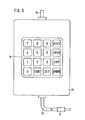
- the electrical control device arranged inside the main battle tank P is shown in FIG. 3. It has a programmable control device 24 of conventional design with an operating panel 18, the control cable 19 and a power supply cable 20 with a plug 21.
- Control commands can be entered on the control panel 18 of the control device 24.
- the control panel which is designed as a conventional 16-key field, contains number keys 0 to 9 as well as function keys with which it is possible to specify the time and revolutions, start and reset the device and make corrections.
- the electric motor 5 runs until the number of revolutions programmed into the control device 24 is registered, then the electric motor 5 switches off and the switching period pause specified on the control device 24 is initiated.
Landscapes
- Engineering & Computer Science (AREA)
- Physics & Mathematics (AREA)
- General Engineering & Computer Science (AREA)
- Electromagnetism (AREA)
- General Physics & Mathematics (AREA)
- Human Computer Interaction (AREA)
- Mechanical Engineering (AREA)
- Toys (AREA)
Applications Claiming Priority (2)
| Application Number | Priority Date | Filing Date | Title |
|---|---|---|---|
| DE3613864 | 1986-04-24 | ||
| DE19863613864 DE3613864A1 (de) | 1986-04-24 | 1986-04-24 | Signaleinrichtung fuer kampffahrzeuge, insbesondere fuer kampfpanzer |
Publications (3)
| Publication Number | Publication Date |
|---|---|
| EP0242679A2 true EP0242679A2 (fr) | 1987-10-28 |
| EP0242679A3 EP0242679A3 (en) | 1989-10-11 |
| EP0242679B1 EP0242679B1 (fr) | 1992-07-29 |
Family
ID=6299431
Family Applications (1)
| Application Number | Title | Priority Date | Filing Date |
|---|---|---|---|
| EP19870105019 Expired - Lifetime EP0242679B1 (fr) | 1986-04-24 | 1987-04-04 | Dispositif de signalisation pour véhicule de combat, en particulier pour tank |
Country Status (2)
| Country | Link |
|---|---|
| EP (1) | EP0242679B1 (fr) |
| DE (2) | DE3613864A1 (fr) |
Family Cites Families (2)
| Publication number | Priority date | Publication date | Assignee | Title |
|---|---|---|---|---|
| CH194304A (de) * | 1935-03-05 | 1937-11-30 | Welter Otto | Signalanlage für den Betrieb mit sichtbaren und infraroten Strahlen. |
| US4357595A (en) * | 1978-01-09 | 1982-11-02 | Federal Signal Corporation | Flashing light warning system for vehicles |
-
1986
- 1986-04-24 DE DE19863613864 patent/DE3613864A1/de not_active Withdrawn
-
1987
- 1987-04-04 DE DE8787105019T patent/DE3780683D1/de not_active Expired - Fee Related
- 1987-04-04 EP EP19870105019 patent/EP0242679B1/fr not_active Expired - Lifetime
Also Published As
| Publication number | Publication date |
|---|---|
| DE3613864A1 (de) | 1987-10-29 |
| EP0242679A3 (en) | 1989-10-11 |
| DE3780683D1 (de) | 1992-09-03 |
| EP0242679B1 (fr) | 1992-07-29 |
Similar Documents
| Publication | Publication Date | Title |
|---|---|---|
| DE2110902C3 (de) | Vorrichtung zum Verdecken einer Beobachtungskamera | |
| DE10103182B4 (de) | Verriegelungsvorrichtung | |
| DE3502095C2 (fr) | ||
| DE2910869A1 (de) | Anlage zum enthaerten von wasser | |
| EP0242679B1 (fr) | Dispositif de signalisation pour véhicule de combat, en particulier pour tank | |
| DE6901312U (de) | Vorrichtung zur anbringung eines kreisschneidewerkzeuges an dem gestell einer motorsaege. | |
| DE69210834T2 (de) | Verstellbare lenksaüle | |
| DE3880150T2 (de) | Sensor fuer fluessigkeitsspiegel. | |
| DE6928766U (de) | Vorrichtung zur bestimmung der lage einer radioaktiven quelle | |
| EP0353646A2 (fr) | Détecteur passif infra-rouge d'intrusion pour surveillance de locaux | |
| DE9107726U1 (de) | Vorrichtung zur Stromübertragung zwischen zwei relativ zueinander beweglichen Endstellen | |
| DE2455455C3 (de) | Verfahren zum Belüften von Gülle in einer beliebig ausgebildeten Güllengrube | |
| DE4426018C2 (de) | Vorrichtung zur Signalübertragung zwischen zwei Endstellen | |
| DE3545023A1 (de) | Signaleinrichtung fuer kampffahrzeuge, insbesondere fuer kampfpanzer | |
| DE1773614C3 (fr) | ||
| DE1014446B (de) | Verschwenkbarer Blendschutz gegen stoerendes Licht, insbesondere fuer Kraftfahrer | |
| DE2713288C3 (de) | Bolzenschweißpistole | |
| DE687149C (de) | Schaltwerk fuer motorische Folgesteuerungen | |
| DE1530480C (de) | Vorrichtung zur selbsttätigen Ein stellung der Lichtbundelneigung eines Kraftfahrzeugscheinwerfers in Abhangig keit vom Belastungszustand des Fahrzeuges | |
| DE9419351U1 (de) | Lampenanordnung für Fahrräder | |
| DE10016249A1 (de) | Vorrichtung zur Verhinderung von Bißschäden an Kraftfahrzeugen | |
| DE7237839U (de) | Einstelleinrichtung fuer kraftfahrzeug-scheinwerfer | |
| DE942196C (de) | Vorrichtung zum Herausholen von Korken aus dem Inneren von Faessern u. dgl. | |
| DE2420349A1 (de) | Scheinwerfer-wischvorrichtung | |
| DE706035C (de) | Vorrichtung zur Ferneinstellung von Waffen auf Luftfahrzeugen |
Legal Events
| Date | Code | Title | Description |
|---|---|---|---|
| PUAI | Public reference made under article 153(3) epc to a published international application that has entered the european phase |
Free format text: ORIGINAL CODE: 0009012 |
|
| AK | Designated contracting states |
Kind code of ref document: A2 Designated state(s): BE CH DE FR GB IT LI NL SE |
|
| PUAL | Search report despatched |
Free format text: ORIGINAL CODE: 0009013 |
|
| AK | Designated contracting states |
Kind code of ref document: A3 Designated state(s): BE CH DE FR GB IT LI NL SE |
|
| 17P | Request for examination filed |
Effective date: 19891103 |
|
| 17Q | First examination report despatched |
Effective date: 19910718 |
|
| GRAA | (expected) grant |
Free format text: ORIGINAL CODE: 0009210 |
|
| AK | Designated contracting states |
Kind code of ref document: B1 Designated state(s): BE CH DE FR GB IT LI NL SE |
|
| ITF | It: translation for a ep patent filed | ||
| REF | Corresponds to: |
Ref document number: 3780683 Country of ref document: DE Date of ref document: 19920903 |
|
| GBT | Gb: translation of ep patent filed (gb section 77(6)(a)/1977) | ||
| ET | Fr: translation filed | ||
| PG25 | Lapsed in a contracting state [announced via postgrant information from national office to epo] |
Ref country code: BE Effective date: 19930430 |
|
| PLBE | No opposition filed within time limit |
Free format text: ORIGINAL CODE: 0009261 |
|
| STAA | Information on the status of an ep patent application or granted ep patent |
Free format text: STATUS: NO OPPOSITION FILED WITHIN TIME LIMIT |
|
| 26N | No opposition filed | ||
| BERE | Be: lapsed |
Owner name: WEGMANN & CO. G.M.B.H. Effective date: 19930430 |
|
| EAL | Se: european patent in force in sweden |
Ref document number: 87105019.1 |
|
| PGFP | Annual fee paid to national office [announced via postgrant information from national office to epo] |
Ref country code: GB Payment date: 19990323 Year of fee payment: 13 |
|
| PGFP | Annual fee paid to national office [announced via postgrant information from national office to epo] |
Ref country code: SE Payment date: 19990414 Year of fee payment: 13 |
|
| PGFP | Annual fee paid to national office [announced via postgrant information from national office to epo] |
Ref country code: CH Payment date: 19990421 Year of fee payment: 13 |
|
| PGFP | Annual fee paid to national office [announced via postgrant information from national office to epo] |
Ref country code: FR Payment date: 19990428 Year of fee payment: 13 |
|
| PGFP | Annual fee paid to national office [announced via postgrant information from national office to epo] |
Ref country code: NL Payment date: 19990429 Year of fee payment: 13 |
|
| PGFP | Annual fee paid to national office [announced via postgrant information from national office to epo] |
Ref country code: DE Payment date: 19990510 Year of fee payment: 13 |
|
| PG25 | Lapsed in a contracting state [announced via postgrant information from national office to epo] |
Ref country code: GB Free format text: LAPSE BECAUSE OF NON-PAYMENT OF DUE FEES Effective date: 20000404 |
|
| PG25 | Lapsed in a contracting state [announced via postgrant information from national office to epo] |
Ref country code: SE Free format text: LAPSE BECAUSE OF NON-PAYMENT OF DUE FEES Effective date: 20000405 |
|
| PG25 | Lapsed in a contracting state [announced via postgrant information from national office to epo] |
Ref country code: LI Free format text: LAPSE BECAUSE OF NON-PAYMENT OF DUE FEES Effective date: 20000430 Ref country code: CH Free format text: LAPSE BECAUSE OF NON-PAYMENT OF DUE FEES Effective date: 20000430 |
|
| PG25 | Lapsed in a contracting state [announced via postgrant information from national office to epo] |
Ref country code: NL Free format text: LAPSE BECAUSE OF NON-PAYMENT OF DUE FEES Effective date: 20001101 |
|
| GBPC | Gb: european patent ceased through non-payment of renewal fee |
Effective date: 20000404 |
|
| EUG | Se: european patent has lapsed |
Ref document number: 87105019.1 |
|
| REG | Reference to a national code |
Ref country code: CH Ref legal event code: PL |
|
| PG25 | Lapsed in a contracting state [announced via postgrant information from national office to epo] |
Ref country code: FR Free format text: LAPSE BECAUSE OF NON-PAYMENT OF DUE FEES Effective date: 20001229 |
|
| NLV4 | Nl: lapsed or anulled due to non-payment of the annual fee |
Effective date: 20001101 |
|
| PG25 | Lapsed in a contracting state [announced via postgrant information from national office to epo] |
Ref country code: DE Free format text: LAPSE BECAUSE OF NON-PAYMENT OF DUE FEES Effective date: 20010201 |
|
| REG | Reference to a national code |
Ref country code: FR Ref legal event code: ST |
|
| PG25 | Lapsed in a contracting state [announced via postgrant information from national office to epo] |
Ref country code: IT Free format text: LAPSE BECAUSE OF NON-PAYMENT OF DUE FEES;WARNING: LAPSES OF ITALIAN PATENTS WITH EFFECTIVE DATE BEFORE 2007 MAY HAVE OCCURRED AT ANY TIME BEFORE 2007. THE CORRECT EFFECTIVE DATE MAY BE DIFFERENT FROM THE ONE RECORDED. Effective date: 20050404 |