EP0242679A2 - Signalling device for combat vehicles, particularly for tanks - Google Patents
Signalling device for combat vehicles, particularly for tanks Download PDFInfo
- Publication number
- EP0242679A2 EP0242679A2 EP87105019A EP87105019A EP0242679A2 EP 0242679 A2 EP0242679 A2 EP 0242679A2 EP 87105019 A EP87105019 A EP 87105019A EP 87105019 A EP87105019 A EP 87105019A EP 0242679 A2 EP0242679 A2 EP 0242679A2
- Authority
- EP
- European Patent Office
- Prior art keywords
- plate
- drive shaft
- rotatable
- combat
- signal
- Prior art date
- Legal status (The legal status is an assumption and is not a legal conclusion. Google has not performed a legal analysis and makes no representation as to the accuracy of the status listed.)
- Granted
Links
Images

Classifications
-
- F—MECHANICAL ENGINEERING; LIGHTING; HEATING; WEAPONS; BLASTING
- F41—WEAPONS
- F41H—ARMOUR; ARMOURED TURRETS; ARMOURED OR ARMED VEHICLES; MEANS OF ATTACK OR DEFENCE, e.g. CAMOUFLAGE, IN GENERAL
- F41H5/00—Armour; Armour plates
- F41H5/26—Peepholes; Windows; Loopholes
-
- B—PERFORMING OPERATIONS; TRANSPORTING
- B60—VEHICLES IN GENERAL
- B60Q—ARRANGEMENT OF SIGNALLING OR LIGHTING DEVICES, THE MOUNTING OR SUPPORTING THEREOF OR CIRCUITS THEREFOR, FOR VEHICLES IN GENERAL
- B60Q9/00—Arrangement or adaptation of signal devices not provided for in one of main groups B60Q1/00 - B60Q7/00, e.g. haptic signalling
-
- F—MECHANICAL ENGINEERING; LIGHTING; HEATING; WEAPONS; BLASTING
- F41—WEAPONS
- F41H—ARMOUR; ARMOURED TURRETS; ARMOURED OR ARMED VEHICLES; MEANS OF ATTACK OR DEFENCE, e.g. CAMOUFLAGE, IN GENERAL
- F41H7/00—Armoured or armed vehicles
- F41H7/02—Land vehicles with enclosing armour, e.g. tanks
-
- G—PHYSICS
- G08—SIGNALLING
- G08B—SIGNALLING OR CALLING SYSTEMS; ORDER TELEGRAPHS; ALARM SYSTEMS
- G08B5/00—Visible signalling systems, e.g. personal calling systems, remote indication of seats occupied
- G08B5/22—Visible signalling systems, e.g. personal calling systems, remote indication of seats occupied using electric transmission; using electromagnetic transmission
- G08B5/36—Visible signalling systems, e.g. personal calling systems, remote indication of seats occupied using electric transmission; using electromagnetic transmission using visible light sources
- G08B5/38—Visible signalling systems, e.g. personal calling systems, remote indication of seats occupied using electric transmission; using electromagnetic transmission using visible light sources using flashing light
Definitions
- the invention relates to a signal device for combat vehicles, in particular for battle tanks, with a flashing device which only emits signals in the thermal image spectrum.
- the above-mentioned older signaling device has a flashing device in which the radiating element can be covered by a motor-driven screen in predetermined directions and a predetermined rhythm.
- the radiating element itself is designed as a cylindrical body, on the inner surface of which a heating mat is arranged and in which an electric motor is arranged, ----------------------------------------------------------- which drives a circumferential diaphragm arranged outside the cylinder tube.
- the radiating element takes up a relatively large amount of space, which has a disadvantageous effect when the signaling device is removed from the combat vehicle and is to be accommodated, for example, inside the vehicle.
- particularly careful measures for thermal insulation between the heating mat and the electric motor arranged inside the heating mat must be provided for a radiating element of this construction.
- the object underlying the invention was to design a signal device of the type mentioned at the outset so that the radiating element takes up as little space as possible and the entire device can be stowed in the smallest possible space.
- the radiating element is particularly well adapted to the conditions which prevail in the case of radiation in the thermal image spectrum.
- the radiating element is a flat plate, which would not be readily possible, for example, with a flashing device which radiates in the range of visible light it is not necessary to provide an additional motorized diaphragm to cover the radiating element in a predetermined rhythm.
- the rotational movement of the radiating element itself means that radiation is emitted only in one direction perpendicular to the radiating surface, while hardly any radiation takes place in the plane of the radiating surface, that is to say in the direction of the narrow sides of the plate.
- the code to be provided is advantageously generated by an electrical control device, for example a programmable control device known per se, with the aid of which it can be programmed how many revolutions the plate should make and which pause lengths between the revolutions should occur.
- an electrical control device for example a programmable control device known per se, with the aid of which it can be programmed how many revolutions the plate should make and which pause lengths between the revolutions should occur.
- an aperture covering approximately half of the radiation area of the radiating element can be provided, which prevents a thermal image signal from being emitted in an undesired direction.
- This additional screen can be designed so that it can be folded up. In this way it is achieved that when the signal device is removed and disassembled, neither the radiating element nor the surrounding diaphragm take up much space.
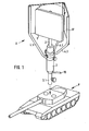
- the flashing device B of a signal device is arranged on a main battle tank P of conventional design, for example on the center of the turret, which signal device is connected via a connecting cable 19 to an electrical control device inside the turret.
- the flashing device B has a holding tube 3 which can be plugged onto a corresponding component on the main battle tank P by means of an attachment piece 3.1 and can be fixed by means of a screw connection 16.
- An electric motor 5 is arranged within the holding tube 3, the output shaft 6 of which is fixedly connected to an axially guided through the holding tube 3 drive shaft 2, which is mounted within the holding tube 3 via rotary bearings 8 and is guided out of the holding tube 3 at the upper end thereof.
- a flat plate 1 is arranged as a radiating element, which, as can be seen from FIG. 2, is made up of several layers.
- An insulating layer 11 is initially arranged on a base plate 12, on which an electric heating mat 9 is placed.
- a good radiating protective layer 10 is placed on the outside of the heating mat 9.
- the radiating surface is thus parallel to the drive shaft 2 and the radiation takes place perpendicular to the central axis of this drive shaft.
- the lead 9.1 to the heating mat 9 is passed through the drive shaft 2 to a ring 7 made of insulating material and is connected there to a slip ring 14 which is opposite a sliding contact 15 arranged on the inner wall of the holding tube 3, to which a lead 9.2 is connected.
- a contact element 7.1 is further provided, opposite to which a sensor 13 which outputs a signal via line 13.1 when the drive shaft 2 rotates, which signal represents a measure of the rotational frequency. Since it is only important at this point to generate signals with the rotational frequency, this sensor 13 can be constructed in very different ways.
- the sensor 13 can be designed as a sliding contact and! the contact piece 7.1 is either connected to ground or to the slip ring 14.
- the contact piece 7.1 can also be designed as a permanent magnet and the sensor 13 as a reed contact. ;
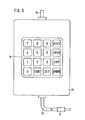
- the lines 9.2 and 13.1 as well as the supply line 5.1 to the motor 5 are led out of the holding tube 3 as a common connecting cable 19 which, as can be seen in FIG. 3, leads to a control device 24.
- This panel consists of a strip 17 made of flexible, foldable material, which is attached to tension rods 4.1, 4.2 and 4.3 is, the bent ends of which are connected to a retaining ring 22 which is attached to the retaining tube 3 and can be fixed thereon by means of a screw connection 23. After loosening the screw connection 23, the diaphragm can be pivoted about the central axis of the holding tube 3. If, as can be seen from FIG.
- the ring 22 consists of three individual rings arranged one above the other, each of which is connected to one of the tension rods 4.1 to 4.3, it is possible to remove the tension rods 4.1 to 4.3 individually when the device is taken apart.
- the panel 17 with the tension rods 4.1 to 4.3 can then be folded up and stowed without taking up much space.
- the electrical control device arranged inside the main battle tank P is shown in FIG. 3. It has a programmable control device 24 of conventional design with an operating panel 18, the control cable 19 and a power supply cable 20 with a plug 21.
- Control commands can be entered on the control panel 18 of the control device 24.
- the control panel which is designed as a conventional 16-key field, contains number keys 0 to 9 as well as function keys with which it is possible to specify the time and revolutions, start and reset the device and make corrections.
- the electric motor 5 runs until the number of revolutions programmed into the control device 24 is registered, then the electric motor 5 switches off and the switching period pause specified on the control device 24 is initiated.
Landscapes
- Engineering & Computer Science (AREA)
- Physics & Mathematics (AREA)
- General Engineering & Computer Science (AREA)
- Electromagnetism (AREA)
- General Physics & Mathematics (AREA)
- Human Computer Interaction (AREA)
- Mechanical Engineering (AREA)
- Toys (AREA)
Abstract
Eine Signaleinrichtung für Kampffahrzeuge, insbesondere für Kampfpanzer, mit einer Blinkvorrichtung, die ausschließlich Signale im Wärmebildspektrum abstrahlt. Das abstrahlende Element der Blinkvorrichtung ist als flache Platte (1) ausgebildet, deren Abstrahlfläche (10) in einer vertikalen Ebene angeordnet ist und die motorisch angetrieben um eine vertikale Achse (2) drehbar ist. Innerhalb der Platte (1) ist eine elektrisch beheizbare Heizmatte (9) angeordnet, deren durch die Antriebswelle (2) geführte Anschlußleitung (9.1,9.2) über eine elektrisch leitende Drehverbindung (7, 15) an eine Stromquelle angeschlossen ist. Durch entsprechende Ansteuerung des Elektromotors (5) von einem Regelgerät imA signaling device for combat vehicles, in particular for battle tanks, with a flashing device that only emits signals in the thermal image spectrum. The radiating element of the flashing device is designed as a flat plate (1), the radiating surface (10) of which is arranged in a vertical plane and which can be rotated in a motor-driven manner about a vertical axis (2). An electrically heatable heating mat (9) is arranged inside the plate (1), the connecting line (9.1, 9.2), which is guided through the drive shaft (2), is connected to a power source via an electrically conductive rotary connection (7, 15). By appropriate control of the electric motor (5) by a control device in the
Inneren des Kampffahrzeugs aus kann die Umlauffrequenz und die zwischen einzelnen Umläufen eincodierten Pausen vorgegeben werden.
Description
Die Erfindung betrifft eine Signaleinrichtung für Kampffahrzeuge, insbesondere für Kampfpanzer, mit einer Blinkvorrichtung, die ausschließlich Signale im Wärmebildspektrum abstrahlt.The invention relates to a signal device for combat vehicles, in particular for battle tanks, with a flashing device which only emits signals in the thermal image spectrum.
Im Gefechtseinsatz ist es erforderlich, daß Kampffahrzeuge, insbesondere Kampfpanzer, zu Zwecken der Gefechtsaufklärung über die eigenen Linien fahren, um dann später nach Erfüllung ihres Auftrages wieder von den eigenen Truppen aufgenommen zu werden. Sofern dies bei Tage stattfindet, werden die eigenen Fahrzeuge bei der Rückkehr von den in Sicherung befindenden eigenen Truppen aufgrund ihrer Silhouette erkannt und deshalb nicht, obwohl vor den eigenen Linien befindlich, beschossen.In combat operations it is necessary that combat vehicles, especially main battle tanks, drive over their own lines for the purpose of combat reconnaissance, so that they can be picked up again later by their own troops after fulfilling their mission. If this takes place during the day, your own vehicles will be recognized by your own troops on the return due to their silhouette and therefore not fired at, even though they are in front of your own lines.
Bei Dunkelheit oder schlechter Sicht ist dieses Verfahren der Erkennung nicht anwendbar und es wurde in der Praxis mit Blinkleuchten und ähnlichen Einrichtungen, die im Bereich des sichtbaren Lichtes liegenden Signale abstrahlen, gearbeitet.This method of detection cannot be used in the dark or in poor visibility, and in practice work has been carried out with flashing lights and similar devices that emit signals in the visible light range.
Diese bekannten Verfahren haben den wesentlichen Nachteil, daß auch der Feind mit bloßem Auge die Blinkzeichen erkennen kann und damit eine Gefährdung des blinkenden Fahrzeuges gegeben ist.These known methods have the major disadvantage that the enemy can also see the blinking signs with the naked eye and thus there is a danger to the blinking vehicle.
Seitdem bei den meisten modernen Armeen Wärmebildgeräte zur Aufklärung der Gefechtsverhältnisse bei Nacht eingesetzt werden, können zwar Fahrzeuge auf relativ große Entfernungen bei Dunkelheit entdeckt werden, jedoch ist die Identifizierung, ob es sich um feindliche oder eigene Fahrzeuge handelt, mit Hilfe des Wärmebildes kaum möglich, so daß für den Beobachter immer Zweifel bestehen, um was für ein Fahrzeug es sich im Vorfeld handelt.Since most modern armies have used thermal imaging devices to clarify the combat situation at night, vehicles can be detected at relatively large distances in the dark, but it is hardly possible to identify whether they are enemy or own vehicles with the help of the thermal image. so that the observer always has doubts as to what kind of vehicle it is in advance.
Zur Behebung dieser Nachteile ist es gemäß einem älteren Vorschlag (P 35 45 023.1) bekannt, eine Signaleinrichtung mit den eingangs und im Oberbegriff des Patentanspruchs 1 angegebenen Merkmalen vorzusehen, die den mit Wärmebildgeräten beobachtenden Truppen die Möglichkeit gibt, eindeutig zu unterscheiden, ob die sich annähernden Kampffahrzeuge im Vorfeld zu eigenen oder feindlichen Kräften gehören.To remedy these disadvantages, it is known, according to an older proposal (P 35 45 023.1), to provide a signaling device with the features specified at the beginning and in the preamble of
Mit einer solchen Signaleinrichtung ist es möglich, in einem als Code zu verstehenden Rhythmus die Blinkvorrichtung auf- oder abzublenden. Dies eröffnet die Möglichkeit, bei den eigenen Truppen im täglichen Wechsel einen bestimmten Auf- und Abblendecode festzulegen, aus dem die beobachtenden Truppen erkennen können, ob es sich bei einem sich nähernden Kampffahrzeug um eigene Kräfte handelt.With such a signal device, it is possible to fade in or out the flashing device in a rhythm to be understood as a code. This opens up the possibility of setting up a specific fade-in and fade-out code for your own troops every day, from which the observing troops can recognize whether an approaching combat vehicle is their own force.
Die obengenannte ältere Signaleinrichtung besitzt eine Blinkvorrichtung, bei der das abstrahlende Element durch eine motorisch angetriebene Blende in vorgegebenen Richtungen und vorgegebenem Rhythmus abdeckbar ist. Das abstrahlende Element selbst ist als zylindrischer Körper ausgebildet, an dessen'innerer Mantelfläche eine Heizmatte angeordnet ist und in dem ein Elektromotor angeordnet ist, ------------------------------------------der eine außerhalb des Zylinderrohres angeordnete umlaufende Blende antreibt.The above-mentioned older signaling device has a flashing device in which the radiating element can be covered by a motor-driven screen in predetermined directions and a predetermined rhythm. The radiating element itself is designed as a cylindrical body, on the inner surface of which a heating mat is arranged and in which an electric motor is arranged, ----------------------- ------------------- which drives a circumferential diaphragm arranged outside the cylinder tube.
Bei dieser Signaleinrichtung nimmt das abstrahlende Element relativ viel Raum ein, was sich nachteilig auswirkt, wenn die Signaleinrichtung vom Kampffahrzeug abgenommen ist und etwa im Inneren des Fahrzeugs untergebracht werden soll. Außerdem müssen bei einem abstrahlenden Element dieser Konstruktion besonders sorgfältige Maßnahmen zur Wärmedämmung zwischen der Heizmatte und dem innerhalb der Heizmatte angeordneten Elektromotor vorgesehen sein.In this signaling device, the radiating element takes up a relatively large amount of space, which has a disadvantageous effect when the signaling device is removed from the combat vehicle and is to be accommodated, for example, inside the vehicle. In addition, particularly careful measures for thermal insulation between the heating mat and the electric motor arranged inside the heating mat must be provided for a radiating element of this construction.
Die der Erfindung zugrunde liegende Aufgabe bestand darin, eine Signaleinrichtung der eingangs erwähnten Art so auszubilden, daß das abstrahlende Element möglichst wenig Raum einnimmt und die ganze Einrichtung auf möglichst kleinem Raum verstaubar ist.The object underlying the invention was to design a signal device of the type mentioned at the outset so that the radiating element takes up as little space as possible and the entire device can be stowed in the smallest possible space.
Die Lösung dieser Aufgabe erfolgt erfindungsgemäß mit den Merkmalen aus dem kennzeichnenden Teil des Patentanspruchs 1.This object is achieved according to the invention with the features from the characterizing part of
Vorteilhafte Ausführungsformen der erfindungsgemäßen Signaleinrichtung sind in den Unteransprüchen beschrieben.Advantageous embodiments of the signal device according to the invention are described in the subclaims.
Das abstrahlende Element ist bei der erfindungsgemäßen Signaleinrichtung an die Verhältnisse, die bei einer Abstrahlung im Wärmebildspektrum vorherrschen, besonders gut angepaßt. Durch die Ausbildung des abstrahlenden Elementes als flache Platte, was beispielsweise bei einer Blinkvorrichtung, die im Bereich des sichtbaren Lichtes abstrahlt, nicht ohne weiteres möglich wäre, ist es nicht notwendig, zur Abdeckung des abstrahlenden Elementes in einem vorgegebenen Rhythmus eine zusätzliche motorisch angetriebene Blende vorzusehen. Vielmehr ergibt sich durch die Drehbewegung des abstrahlenden Elementes selbst, daß jeweils nur in einer Richtung senkrecht zur Abstrahlfläche abgestrahlt wird, während in der Ebene der Abstrahlfläche, also in Richtung der Schmalseiten der Platte, kaum eine Abstrahlung erfolgt. Dies hat zur Folge, daß bei einer Drehung der Platte aus der Sicht eines entfernt stehenden Beobachters die Wärmequelle scheinbar rhythmisch abgedeckt wird und pulsierend erscheint.In the signal device according to the invention, the radiating element is particularly well adapted to the conditions which prevail in the case of radiation in the thermal image spectrum. By designing the radiating element as a flat plate, which would not be readily possible, for example, with a flashing device which radiates in the range of visible light it is not necessary to provide an additional motorized diaphragm to cover the radiating element in a predetermined rhythm. Rather, the rotational movement of the radiating element itself means that radiation is emitted only in one direction perpendicular to the radiating surface, while hardly any radiation takes place in the plane of the radiating surface, that is to say in the direction of the narrow sides of the plate. As a result, when the plate is rotated from the perspective of a distant observer, the heat source appears to be covered rhythmically and appears pulsating.
Der vorzusehende Code wird vorteilhaft durch ein elektrisches Steuergerät, beispielsweise ein an sich bekanntes programmierbares Regelgerät, erzeugt, mit dessen Hilfe einprogrammiert werden kann, wieviele Umdrehungen die Platte machen soll und welche Pausenlängen zwischen den Umdrehungen auftreten sollen.The code to be provided is advantageously generated by an electrical control device, for example a programmable control device known per se, with the aid of which it can be programmed how many revolutions the plate should make and which pause lengths between the revolutions should occur.
Bei einer vorteilhaften Ausführungsform der Signaleinrichtung kann eine, etwa die Hälfte des Abstrahlbereiches des abstrahlenden Elementes abdeckende Blende vorgesehen sein, durch die verhindert wird, daß in eine ungewünschte Richtung ein Wärmebildsignal abgegeben wird. Diese zusätzliche Blende kann (Patentanspruch 3) so ausgebildet sein, daß sie zusammenfaltbar ist. Auf diese Weise wird erreicht, daß beim Abnehmen und Zerlegen der Signaleinrichtung weder das abstrahlende Element noch die umgebende Blende viel Raum einnehmen.In an advantageous embodiment of the signaling device, an aperture covering approximately half of the radiation area of the radiating element can be provided, which prevents a thermal image signal from being emitted in an undesired direction. This additional screen can be designed so that it can be folded up. In this way it is achieved that when the signal device is removed and disassembled, neither the radiating element nor the surrounding diaphragm take up much space.
Im folgenden wird ein Ausführungsbeispiel für eine Signaleinrichtung nach der Erfindung anhand der Zeichnungen erläutert.An exemplary embodiment of a signal device according to the invention is explained below with reference to the drawings.
In den Zeichnungen zeigen:
- Fig. 1 in perspektivischer Darstellung einen Kampfpanzer mit darüber angeordneter vergrößert dargestellter Signaleinrichtung;
- Fig. 2 einen Schnitt durch die Blinkvorrichtung der Signaleinrichtung nach Fig. 1;
- Fig. 3 in einer Draufsicht eine elektrische Steuereinrichtung für die Signaleinrichtung nach Fig. 1 und 2.
- Figure 1 is a perspective view of a battle tank with signaling device shown above and enlarged.
- FIG. 2 shows a section through the flashing device of the signal device according to FIG. 1;
- 3 shows a top view of an electrical control device for the signal device according to FIGS. 1 and 2.
Wie in Fig. 1 angedeutet, ist auf einem Kampfpanzer P herkömmlicher Bauart, beispielsweise auf der Turmmitte, die Blinkvorrichtung B einer Signaleinrichtung angeordnet, die über ein Anschlußkabel 19 mit einer elektrischen Steuereinrichtung im Turminneren verbunden ist.As indicated in FIG. 1, the flashing device B of a signal device is arranged on a main battle tank P of conventional design, for example on the center of the turret, which signal device is connected via a connecting
Wie aus den Fig. 1 und 2 ersichtlich, besitzt die Blinkvorrichtung B eine Halterohr 3, das mittels eines Ansatzstückes 3.1 auf ein entsprechendes Bauteil am Kampfpanzer P aufsteckbar und mittels einer Schraubverbindung 16 festlegbar ist. Innerhalb des Halterohrs 3 ist ein Elektromotor 5 angeordnet, dessen Abtriebswelle 6 fest mit einer axial durch das Halterohr 3 geführten Antriebswelle 2 verbunden ist, die innerhalb des Halterohrs 3 über Drehlager 8 gelagert ist und am oberen Ende des Halterohrs 3 aus diesem herausgeführt ist. Am freien, aus dem Halterohr 3 herausgeführten Ende der Antriebswelle 2 ist als abstrahlendes Element eine flache Platte 1 angeordnet, die, wie aus Fig. 2 ersichtlich, aus mehreren Schichten aufgebaut ist. Auf einer Grundplatte 12 ist zunächst eine isolierende Schicht 11 angeordnet, auf die eine elektrische Heizmatte 9 aufgelegt ist. An der Außenseite ist auf die Heizmatte 9 eine gut abstrahlende Schutzschicht 10 aufgelegt.As can be seen from FIGS. 1 and 2, the flashing device B has a
Die abstrahlende Fläche liegt somit parallel zur Antriebswelle 2 und die Abstrahlung erfolgt jeweils senkrecht zur Mittelachse dieser Antriebswelle.The radiating surface is thus parallel to the
Die Zuleitung 9.1 zur Heizmatte 9 ist durch die Antriebswelle 2 hindurchgeführt bis zu einem Ring 7 aus isolierendem Material und dort mit einem Schleifring 14 verbunden, dem ein an der Innenwand des Halterohrs 3 angeordneter Schleifkontakt 15 gegenüberliegt, an den eine Zuleitung 9.2 angeschlossen ist.The lead 9.1 to the
In dem zusammen mit der Antriebswelle 2 rotierenden Ring 7 ist weiterhin ein Kontaktelement 7.1 vorgesehen, dem ein Sensor 13 gegenüberliegt, der über eine Leitung 13.1 beim Rotieren der Antriebswelle 2 ein Signal abgibt, welches ein Maß für die Umlauffrequenz darstellt. Da es an dieser Stelle nur darauf ankommt, Signale mit der Umlauffrequenz zu erzeugen, kann dieser Sensor 13 sehr verschiedenartig aufgebaut sein. So kann beispielsweise der Sensor 13 als Schleifkontakt ausgebildet sein und ! das Kontaktstück 7.1 ist entweder mit Masse oder mit dem Schleifring 14 verbunden. Es kann aber auch das Kontaktstück 7.1 als Permanentmagnet und der Sensor 13 als Reed-Kontakt ausgebildet sein. ;In the
Die Leitungen 9.2 und 13.1 sowie die Zuleitung 5.1 zum Motor 5 sind aus dem Halterohr 3 als gemeinsames Anschlußkabel 19 herausgeführt, das, wie aus Fig. 3 er- sichtlich, zu einer Steuereinrichtung 24 führt.The lines 9.2 and 13.1 as well as the supply line 5.1 to the
Außerhalb des Drehbereichs der Platte 1 ist eine zusätzliche Blende angeordnet, die eine Abstrahlung in eine unerwünschte Richtung verhindern soll. Diese Blende besteht aus einem Streifen 17 aus flexiblem faltbarem Material, der an Spannstäben 4.1, 4.2 und 4.3 befestigt ist, deren abgebogene Enden mit einem Halterungsring 22 verbunden sind, der auf das Halterohr 3 aufgesteckt ist und an diesem über eine Schraubverbindung 23 festlegbar ist. Die Blende kann nach Lösen der Schraubverbindung 23 um die Mittelachse des Halterohrs 3 verschwenkt werden. Wenn, wie aus Fig. 1-zu entnehmen, der Ring 22 aus drei übereinander angeordneten Einzelringen besteht, von denen jeder mit einem der Spannstäbe 4.1 bis 4.3 verbunden ist, ist es möglich, die Spannstäbe 4.1 bis 4.3 beim Auseinandernehmen der Einrichtung einzeln abzunehmen. Die Blende 17 mit den Spannstäben 4.1 bis 4.3 kann dann zusammengefaltet und ohne großen Raumbedarf verstaut werden.An additional screen is arranged outside the rotating range of the
Die im Inneren des Kampfpanzers P angeordnete elektrische Steuereinrichtung ist in Fig. 3 dargestellt. Sie weist ein programmierbares Regelgerät 24 herkömmlicher Bauart auf mit einem Bedienungsfeld 18, dem Steuerkabel 19 und einem Stromversorgungskabel 20 mit Bordstecker 21.The electrical control device arranged inside the main battle tank P is shown in FIG. 3. It has a
Die Funktionsweise der in den Fig. 1 bis 3 dargestellten . Vorrichtung ist folgende:
- Der Strom aus dem Bordnetz des Kampfpanzers P fließt beim Einschalten der Anlage über das
Kabel 19 zurHeizmatte 9, die dieSchutzschicht 10 erwärmt. Von der erwärmten Abstrahlfläche derSchutzschicht 10 geht die Wärmestrahlung nach außen, so daß sie von Wärmebildgeräten aufgenommen werden kann. DiePlatte 1 dreht sich in gewünschter Häufigkeit um die Achse derAntriebswelle 2, indem derElektromotor 5 für eine vorgegebene Zeit mit Strom versorgt wird. Die Anzahl die Drehungen wird durch denSensor 13 registriert, wobei entsprechende Signale erzeugt und demRegelgerät 24 zugeführt werden.
- The current from the electrical system of the main battle tank P flows when the system is switched on via the
cable 19 to theheating mat 9, which heats theprotective layer 10. From the heated radiation surface of theprotective layer 10, the heat radiation goes out, so that it can be absorbed by thermal imaging devices. Theplate 1 rotates in the desired frequency around the axis of thedrive shaft 2 by supplying theelectric motor 5 with power for a predetermined time. The number of rotations is registered by thesensor 13, corresponding signals being generated and fed to thecontrol device 24.
Am Bedienungsfeld 18 des Regelgerätes 24 können Steuerbefehle eingegeben werden. Das als übliches 16-Tastenfeld ausgebildete Bedienungsfeld enthält Zahlentasten 0 bis 9 sowie Funktionstasten, mit denen eine Vorgabe der Zeit und der Umdrehungen, Start und Rücksetzen der Einrichtung sowie die Vornahme von Korrekturen möglich ist.Control commands can be entered on the
Der Elektromotor 5 läuft solange bis die Anzahl der am Regelgerät 24 einprogrammierten Umdrehungen registriert sind, dann schaltet der Elektromotor 5 ab und die am Regelgerät 24 vorgegebene Schaltdauerpause wird eingeleitet.The
Claims (6)
Applications Claiming Priority (2)
| Application Number | Priority Date | Filing Date | Title |
|---|---|---|---|
| DE3613864 | 1986-04-24 | ||
| DE19863613864 DE3613864A1 (en) | 1986-04-24 | 1986-04-24 | SIGNALING DEVICE FOR COMBAT VEHICLES, ESPECIALLY FOR COMBAT TANKS |
Publications (3)
| Publication Number | Publication Date |
|---|---|
| EP0242679A2 true EP0242679A2 (en) | 1987-10-28 |
| EP0242679A3 EP0242679A3 (en) | 1989-10-11 |
| EP0242679B1 EP0242679B1 (en) | 1992-07-29 |
Family
ID=6299431
Family Applications (1)
| Application Number | Title | Priority Date | Filing Date |
|---|---|---|---|
| EP19870105019 Expired - Lifetime EP0242679B1 (en) | 1986-04-24 | 1987-04-04 | Signalling device for combat vehicles, particularly for tanks |
Country Status (2)
| Country | Link |
|---|---|
| EP (1) | EP0242679B1 (en) |
| DE (2) | DE3613864A1 (en) |
Family Cites Families (2)
| Publication number | Priority date | Publication date | Assignee | Title |
|---|---|---|---|---|
| CH194304A (en) * | 1935-03-05 | 1937-11-30 | Welter Otto | Signal system for operation with visible and infrared rays. |
| US4357595A (en) * | 1978-01-09 | 1982-11-02 | Federal Signal Corporation | Flashing light warning system for vehicles |
-
1986
- 1986-04-24 DE DE19863613864 patent/DE3613864A1/en not_active Withdrawn
-
1987
- 1987-04-04 DE DE8787105019T patent/DE3780683D1/en not_active Expired - Fee Related
- 1987-04-04 EP EP19870105019 patent/EP0242679B1/en not_active Expired - Lifetime
Also Published As
| Publication number | Publication date |
|---|---|
| DE3613864A1 (en) | 1987-10-29 |
| EP0242679A3 (en) | 1989-10-11 |
| DE3780683D1 (en) | 1992-09-03 |
| EP0242679B1 (en) | 1992-07-29 |
Similar Documents
| Publication | Publication Date | Title |
|---|---|---|
| DE2110902C3 (en) | Device for concealing an observation camera | |
| DE10103182B4 (en) | locking device | |
| DE3502095C2 (en) | ||
| DE2910869A1 (en) | WATER SOFTENING PLANT | |
| EP0242679B1 (en) | Signalling device for combat vehicles, particularly for tanks | |
| DE6901312U (en) | DEVICE FOR ATTACHING A CIRCULAR CUTTING TOOL TO THE FRAME OF A MOTORSAW. | |
| DE69210834T2 (en) | ADJUSTABLE STEERING COLUMN | |
| DE3880150T2 (en) | SENSOR FOR LIQUID MIRRORS. | |
| DE6928766U (en) | DEVICE FOR DETERMINING THE LOCATION OF A RADIOACTIVE SOURCE | |
| EP0353646A2 (en) | Passive infrared intrusion detector for monitoring spaces | |
| DE9107726U1 (en) | Device for power transmission between two relatively movable end points | |
| DE2455455C3 (en) | Method for aerating liquid manure in a slurry pit of any configuration | |
| DE4426018C2 (en) | Device for signal transmission between two end points | |
| DE3545023A1 (en) | SIGNALING DEVICE FOR COMBAT VEHICLES, ESPECIALLY FOR COMBAT TANKS | |
| DE1773614C3 (en) | ||
| DE1014446B (en) | Swiveling glare protection against disturbing light, especially for drivers | |
| DE2713288C3 (en) | Stud welding gun | |
| DE687149C (en) | Switching mechanism for motorized sequence controls | |
| DE1530480C (en) | Device for automatic adjustment of the light beam inclination of a motor vehicle headlight in dependence on the load condition of the vehicle | |
| DE9419351U1 (en) | Lamp assembly for bicycles | |
| DE10016249A1 (en) | Device for preventing bite damage in motor vehicles has flash tube activated by movement sensor to give off flash signals, is controled by flash electrode, supplied by vehicle accumulator | |
| DE7237839U (en) | ADJUSTMENT DEVICE FOR MOTOR VEHICLE HEADLIGHTS | |
| DE942196C (en) | Device for extracting corks from the inside of barrels u. like | |
| DE2420349A1 (en) | HEADLAMP WIPER | |
| DE706035C (en) | Device for remote adjustment of weapons on aircraft |
Legal Events
| Date | Code | Title | Description |
|---|---|---|---|
| PUAI | Public reference made under article 153(3) epc to a published international application that has entered the european phase |
Free format text: ORIGINAL CODE: 0009012 |
|
| AK | Designated contracting states |
Kind code of ref document: A2 Designated state(s): BE CH DE FR GB IT LI NL SE |
|
| PUAL | Search report despatched |
Free format text: ORIGINAL CODE: 0009013 |
|
| AK | Designated contracting states |
Kind code of ref document: A3 Designated state(s): BE CH DE FR GB IT LI NL SE |
|
| 17P | Request for examination filed |
Effective date: 19891103 |
|
| 17Q | First examination report despatched |
Effective date: 19910718 |
|
| GRAA | (expected) grant |
Free format text: ORIGINAL CODE: 0009210 |
|
| AK | Designated contracting states |
Kind code of ref document: B1 Designated state(s): BE CH DE FR GB IT LI NL SE |
|
| ITF | It: translation for a ep patent filed | ||
| REF | Corresponds to: |
Ref document number: 3780683 Country of ref document: DE Date of ref document: 19920903 |
|
| GBT | Gb: translation of ep patent filed (gb section 77(6)(a)/1977) | ||
| ET | Fr: translation filed | ||
| PG25 | Lapsed in a contracting state [announced via postgrant information from national office to epo] |
Ref country code: BE Effective date: 19930430 |
|
| PLBE | No opposition filed within time limit |
Free format text: ORIGINAL CODE: 0009261 |
|
| STAA | Information on the status of an ep patent application or granted ep patent |
Free format text: STATUS: NO OPPOSITION FILED WITHIN TIME LIMIT |
|
| 26N | No opposition filed | ||
| BERE | Be: lapsed |
Owner name: WEGMANN & CO. G.M.B.H. Effective date: 19930430 |
|
| EAL | Se: european patent in force in sweden |
Ref document number: 87105019.1 |
|
| PGFP | Annual fee paid to national office [announced via postgrant information from national office to epo] |
Ref country code: GB Payment date: 19990323 Year of fee payment: 13 |
|
| PGFP | Annual fee paid to national office [announced via postgrant information from national office to epo] |
Ref country code: SE Payment date: 19990414 Year of fee payment: 13 |
|
| PGFP | Annual fee paid to national office [announced via postgrant information from national office to epo] |
Ref country code: CH Payment date: 19990421 Year of fee payment: 13 |
|
| PGFP | Annual fee paid to national office [announced via postgrant information from national office to epo] |
Ref country code: FR Payment date: 19990428 Year of fee payment: 13 |
|
| PGFP | Annual fee paid to national office [announced via postgrant information from national office to epo] |
Ref country code: NL Payment date: 19990429 Year of fee payment: 13 |
|
| PGFP | Annual fee paid to national office [announced via postgrant information from national office to epo] |
Ref country code: DE Payment date: 19990510 Year of fee payment: 13 |
|
| PG25 | Lapsed in a contracting state [announced via postgrant information from national office to epo] |
Ref country code: GB Free format text: LAPSE BECAUSE OF NON-PAYMENT OF DUE FEES Effective date: 20000404 |
|
| PG25 | Lapsed in a contracting state [announced via postgrant information from national office to epo] |
Ref country code: SE Free format text: LAPSE BECAUSE OF NON-PAYMENT OF DUE FEES Effective date: 20000405 |
|
| PG25 | Lapsed in a contracting state [announced via postgrant information from national office to epo] |
Ref country code: LI Free format text: LAPSE BECAUSE OF NON-PAYMENT OF DUE FEES Effective date: 20000430 Ref country code: CH Free format text: LAPSE BECAUSE OF NON-PAYMENT OF DUE FEES Effective date: 20000430 |
|
| PG25 | Lapsed in a contracting state [announced via postgrant information from national office to epo] |
Ref country code: NL Free format text: LAPSE BECAUSE OF NON-PAYMENT OF DUE FEES Effective date: 20001101 |
|
| GBPC | Gb: european patent ceased through non-payment of renewal fee |
Effective date: 20000404 |
|
| EUG | Se: european patent has lapsed |
Ref document number: 87105019.1 |
|
| REG | Reference to a national code |
Ref country code: CH Ref legal event code: PL |
|
| PG25 | Lapsed in a contracting state [announced via postgrant information from national office to epo] |
Ref country code: FR Free format text: LAPSE BECAUSE OF NON-PAYMENT OF DUE FEES Effective date: 20001229 |
|
| NLV4 | Nl: lapsed or anulled due to non-payment of the annual fee |
Effective date: 20001101 |
|
| PG25 | Lapsed in a contracting state [announced via postgrant information from national office to epo] |
Ref country code: DE Free format text: LAPSE BECAUSE OF NON-PAYMENT OF DUE FEES Effective date: 20010201 |
|
| REG | Reference to a national code |
Ref country code: FR Ref legal event code: ST |
|
| PG25 | Lapsed in a contracting state [announced via postgrant information from national office to epo] |
Ref country code: IT Free format text: LAPSE BECAUSE OF NON-PAYMENT OF DUE FEES;WARNING: LAPSES OF ITALIAN PATENTS WITH EFFECTIVE DATE BEFORE 2007 MAY HAVE OCCURRED AT ANY TIME BEFORE 2007. THE CORRECT EFFECTIVE DATE MAY BE DIFFERENT FROM THE ONE RECORDED. Effective date: 20050404 |