EP0240695A2 - Vorrichtung zum Herstellen von Beutelpackungen mit Entnahmestutzen - Google Patents
Vorrichtung zum Herstellen von Beutelpackungen mit Entnahmestutzen Download PDFInfo
- Publication number
- EP0240695A2 EP0240695A2 EP87102776A EP87102776A EP0240695A2 EP 0240695 A2 EP0240695 A2 EP 0240695A2 EP 87102776 A EP87102776 A EP 87102776A EP 87102776 A EP87102776 A EP 87102776A EP 0240695 A2 EP0240695 A2 EP 0240695A2
- Authority
- EP
- European Patent Office
- Prior art keywords
- hose
- tube
- packaging material
- former
- stamp
- Prior art date
- Legal status (The legal status is an assumption and is not a legal conclusion. Google has not performed a legal analysis and makes no representation as to the accuracy of the status listed.)
- Withdrawn
Links
Images
Classifications
-
- B—PERFORMING OPERATIONS; TRANSPORTING
- B29—WORKING OF PLASTICS; WORKING OF SUBSTANCES IN A PLASTIC STATE IN GENERAL
- B29C—SHAPING OR JOINING OF PLASTICS; SHAPING OF MATERIAL IN A PLASTIC STATE, NOT OTHERWISE PROVIDED FOR; AFTER-TREATMENT OF THE SHAPED PRODUCTS, e.g. REPAIRING
- B29C66/00—General aspects of processes or apparatus for joining preformed parts
- B29C66/40—General aspects of joining substantially flat articles, e.g. plates, sheets or web-like materials; Making flat seams in tubular or hollow articles; Joining single elements to substantially flat surfaces
- B29C66/47—Joining single elements to sheets, plates or other substantially flat surfaces
- B29C66/474—Joining single elements to sheets, plates or other substantially flat surfaces said single elements being substantially non-flat
- B29C66/4742—Joining single elements to sheets, plates or other substantially flat surfaces said single elements being substantially non-flat said single elements being spouts
- B29C66/47421—Joining single elements to sheets, plates or other substantially flat surfaces said single elements being substantially non-flat said single elements being spouts said spouts comprising flanges
-
- B—PERFORMING OPERATIONS; TRANSPORTING
- B29—WORKING OF PLASTICS; WORKING OF SUBSTANCES IN A PLASTIC STATE IN GENERAL
- B29C—SHAPING OR JOINING OF PLASTICS; SHAPING OF MATERIAL IN A PLASTIC STATE, NOT OTHERWISE PROVIDED FOR; AFTER-TREATMENT OF THE SHAPED PRODUCTS, e.g. REPAIRING
- B29C65/00—Joining or sealing of preformed parts, e.g. welding of plastics materials; Apparatus therefor
- B29C65/02—Joining or sealing of preformed parts, e.g. welding of plastics materials; Apparatus therefor by heating, with or without pressure
- B29C65/18—Joining or sealing of preformed parts, e.g. welding of plastics materials; Apparatus therefor by heating, with or without pressure using heated tools
-
- B—PERFORMING OPERATIONS; TRANSPORTING
- B29—WORKING OF PLASTICS; WORKING OF SUBSTANCES IN A PLASTIC STATE IN GENERAL
- B29C—SHAPING OR JOINING OF PLASTICS; SHAPING OF MATERIAL IN A PLASTIC STATE, NOT OTHERWISE PROVIDED FOR; AFTER-TREATMENT OF THE SHAPED PRODUCTS, e.g. REPAIRING
- B29C65/00—Joining or sealing of preformed parts, e.g. welding of plastics materials; Apparatus therefor
- B29C65/78—Means for handling the parts to be joined, e.g. for making containers or hollow articles, e.g. means for handling sheets, plates, web-like materials, tubular articles, hollow articles or elements to be joined therewith; Means for discharging the joined articles from the joining apparatus
- B29C65/7841—Holding or clamping means for handling purposes
- B29C65/7847—Holding or clamping means for handling purposes using vacuum to hold at least one of the parts to be joined
-
- B—PERFORMING OPERATIONS; TRANSPORTING
- B29—WORKING OF PLASTICS; WORKING OF SUBSTANCES IN A PLASTIC STATE IN GENERAL
- B29C—SHAPING OR JOINING OF PLASTICS; SHAPING OF MATERIAL IN A PLASTIC STATE, NOT OTHERWISE PROVIDED FOR; AFTER-TREATMENT OF THE SHAPED PRODUCTS, e.g. REPAIRING
- B29C66/00—General aspects of processes or apparatus for joining preformed parts
- B29C66/01—General aspects dealing with the joint area or with the area to be joined
- B29C66/05—Particular design of joint configurations
- B29C66/10—Particular design of joint configurations particular design of the joint cross-sections
- B29C66/11—Joint cross-sections comprising a single joint-segment, i.e. one of the parts to be joined comprising a single joint-segment in the joint cross-section
- B29C66/112—Single lapped joints
-
- B—PERFORMING OPERATIONS; TRANSPORTING
- B29—WORKING OF PLASTICS; WORKING OF SUBSTANCES IN A PLASTIC STATE IN GENERAL
- B29C—SHAPING OR JOINING OF PLASTICS; SHAPING OF MATERIAL IN A PLASTIC STATE, NOT OTHERWISE PROVIDED FOR; AFTER-TREATMENT OF THE SHAPED PRODUCTS, e.g. REPAIRING
- B29C66/00—General aspects of processes or apparatus for joining preformed parts
- B29C66/01—General aspects dealing with the joint area or with the area to be joined
- B29C66/05—Particular design of joint configurations
- B29C66/10—Particular design of joint configurations particular design of the joint cross-sections
- B29C66/13—Single flanged joints; Fin-type joints; Single hem joints; Edge joints; Interpenetrating fingered joints; Other specific particular designs of joint cross-sections not provided for in groups B29C66/11 - B29C66/12
- B29C66/131—Single flanged joints, i.e. one of the parts to be joined being rigid and flanged in the joint area
-
- B—PERFORMING OPERATIONS; TRANSPORTING
- B29—WORKING OF PLASTICS; WORKING OF SUBSTANCES IN A PLASTIC STATE IN GENERAL
- B29C—SHAPING OR JOINING OF PLASTICS; SHAPING OF MATERIAL IN A PLASTIC STATE, NOT OTHERWISE PROVIDED FOR; AFTER-TREATMENT OF THE SHAPED PRODUCTS, e.g. REPAIRING
- B29C66/00—General aspects of processes or apparatus for joining preformed parts
- B29C66/40—General aspects of joining substantially flat articles, e.g. plates, sheets or web-like materials; Making flat seams in tubular or hollow articles; Joining single elements to substantially flat surfaces
- B29C66/49—Internally supporting the, e.g. tubular, article during joining
-
- B—PERFORMING OPERATIONS; TRANSPORTING
- B29—WORKING OF PLASTICS; WORKING OF SUBSTANCES IN A PLASTIC STATE IN GENERAL
- B29C—SHAPING OR JOINING OF PLASTICS; SHAPING OF MATERIAL IN A PLASTIC STATE, NOT OTHERWISE PROVIDED FOR; AFTER-TREATMENT OF THE SHAPED PRODUCTS, e.g. REPAIRING
- B29C66/00—General aspects of processes or apparatus for joining preformed parts
- B29C66/80—General aspects of machine operations or constructions and parts thereof
- B29C66/81—General aspects of the pressing elements, i.e. the elements applying pressure on the parts to be joined in the area to be joined, e.g. the welding jaws or clamps
- B29C66/814—General aspects of the pressing elements, i.e. the elements applying pressure on the parts to be joined in the area to be joined, e.g. the welding jaws or clamps characterised by the design of the pressing elements, e.g. of the welding jaws or clamps
- B29C66/8141—General aspects of the pressing elements, i.e. the elements applying pressure on the parts to be joined in the area to be joined, e.g. the welding jaws or clamps characterised by the design of the pressing elements, e.g. of the welding jaws or clamps characterised by the surface geometry of the part of the pressing elements, e.g. welding jaws or clamps, coming into contact with the parts to be joined
- B29C66/81431—General aspects of the pressing elements, i.e. the elements applying pressure on the parts to be joined in the area to be joined, e.g. the welding jaws or clamps characterised by the design of the pressing elements, e.g. of the welding jaws or clamps characterised by the surface geometry of the part of the pressing elements, e.g. welding jaws or clamps, coming into contact with the parts to be joined comprising a single cavity, e.g. a groove
-
- B—PERFORMING OPERATIONS; TRANSPORTING
- B29—WORKING OF PLASTICS; WORKING OF SUBSTANCES IN A PLASTIC STATE IN GENERAL
- B29C—SHAPING OR JOINING OF PLASTICS; SHAPING OF MATERIAL IN A PLASTIC STATE, NOT OTHERWISE PROVIDED FOR; AFTER-TREATMENT OF THE SHAPED PRODUCTS, e.g. REPAIRING
- B29C66/00—General aspects of processes or apparatus for joining preformed parts
- B29C66/80—General aspects of machine operations or constructions and parts thereof
- B29C66/83—General aspects of machine operations or constructions and parts thereof characterised by the movement of the joining or pressing tools
- B29C66/832—Reciprocating joining or pressing tools
- B29C66/8322—Joining or pressing tools reciprocating along one axis
- B29C66/83221—Joining or pressing tools reciprocating along one axis cooperating reciprocating tools, each tool reciprocating along one axis
-
- B—PERFORMING OPERATIONS; TRANSPORTING
- B29—WORKING OF PLASTICS; WORKING OF SUBSTANCES IN A PLASTIC STATE IN GENERAL
- B29C—SHAPING OR JOINING OF PLASTICS; SHAPING OF MATERIAL IN A PLASTIC STATE, NOT OTHERWISE PROVIDED FOR; AFTER-TREATMENT OF THE SHAPED PRODUCTS, e.g. REPAIRING
- B29C66/00—General aspects of processes or apparatus for joining preformed parts
- B29C66/80—General aspects of machine operations or constructions and parts thereof
- B29C66/84—Specific machine types or machines suitable for specific applications
- B29C66/849—Packaging machines
-
- B—PERFORMING OPERATIONS; TRANSPORTING
- B65—CONVEYING; PACKING; STORING; HANDLING THIN OR FILAMENTARY MATERIAL
- B65B—MACHINES, APPARATUS OR DEVICES FOR, OR METHODS OF, PACKAGING ARTICLES OR MATERIALS; UNPACKING
- B65B61/00—Auxiliary devices, not otherwise provided for, for operating on sheets, blanks, webs, binding material, containers or packages
- B65B61/18—Auxiliary devices, not otherwise provided for, for operating on sheets, blanks, webs, binding material, containers or packages for making package-opening or unpacking elements
- B65B61/186—Auxiliary devices, not otherwise provided for, for operating on sheets, blanks, webs, binding material, containers or packages for making package-opening or unpacking elements by applying or incorporating rigid fittings, e.g. discharge spouts
-
- B—PERFORMING OPERATIONS; TRANSPORTING
- B29—WORKING OF PLASTICS; WORKING OF SUBSTANCES IN A PLASTIC STATE IN GENERAL
- B29C—SHAPING OR JOINING OF PLASTICS; SHAPING OF MATERIAL IN A PLASTIC STATE, NOT OTHERWISE PROVIDED FOR; AFTER-TREATMENT OF THE SHAPED PRODUCTS, e.g. REPAIRING
- B29C2793/00—Shaping techniques involving a cutting or machining operation
- B29C2793/0009—Cutting out
- B29C2793/0018—Cutting out for making a hole
-
- B—PERFORMING OPERATIONS; TRANSPORTING
- B29—WORKING OF PLASTICS; WORKING OF SUBSTANCES IN A PLASTIC STATE IN GENERAL
- B29C—SHAPING OR JOINING OF PLASTICS; SHAPING OF MATERIAL IN A PLASTIC STATE, NOT OTHERWISE PROVIDED FOR; AFTER-TREATMENT OF THE SHAPED PRODUCTS, e.g. REPAIRING
- B29C2793/00—Shaping techniques involving a cutting or machining operation
- B29C2793/0081—Shaping techniques involving a cutting or machining operation before shaping
-
- B—PERFORMING OPERATIONS; TRANSPORTING
- B29—WORKING OF PLASTICS; WORKING OF SUBSTANCES IN A PLASTIC STATE IN GENERAL
- B29C—SHAPING OR JOINING OF PLASTICS; SHAPING OF MATERIAL IN A PLASTIC STATE, NOT OTHERWISE PROVIDED FOR; AFTER-TREATMENT OF THE SHAPED PRODUCTS, e.g. REPAIRING
- B29C65/00—Joining or sealing of preformed parts, e.g. welding of plastics materials; Apparatus therefor
- B29C65/02—Joining or sealing of preformed parts, e.g. welding of plastics materials; Apparatus therefor by heating, with or without pressure
- B29C65/18—Joining or sealing of preformed parts, e.g. welding of plastics materials; Apparatus therefor by heating, with or without pressure using heated tools
- B29C65/24—Joining or sealing of preformed parts, e.g. welding of plastics materials; Apparatus therefor by heating, with or without pressure using heated tools characterised by the means for heating the tool
- B29C65/30—Electrical means
- B29C65/305—Electrical means involving the use of cartridge heaters
-
- B—PERFORMING OPERATIONS; TRANSPORTING
- B29—WORKING OF PLASTICS; WORKING OF SUBSTANCES IN A PLASTIC STATE IN GENERAL
- B29C—SHAPING OR JOINING OF PLASTICS; SHAPING OF MATERIAL IN A PLASTIC STATE, NOT OTHERWISE PROVIDED FOR; AFTER-TREATMENT OF THE SHAPED PRODUCTS, e.g. REPAIRING
- B29C66/00—General aspects of processes or apparatus for joining preformed parts
- B29C66/01—General aspects dealing with the joint area or with the area to be joined
- B29C66/05—Particular design of joint configurations
- B29C66/10—Particular design of joint configurations particular design of the joint cross-sections
- B29C66/11—Joint cross-sections comprising a single joint-segment, i.e. one of the parts to be joined comprising a single joint-segment in the joint cross-section
- B29C66/112—Single lapped joints
- B29C66/1122—Single lap to lap joints, i.e. overlap joints
-
- B—PERFORMING OPERATIONS; TRANSPORTING
- B29—WORKING OF PLASTICS; WORKING OF SUBSTANCES IN A PLASTIC STATE IN GENERAL
- B29C—SHAPING OR JOINING OF PLASTICS; SHAPING OF MATERIAL IN A PLASTIC STATE, NOT OTHERWISE PROVIDED FOR; AFTER-TREATMENT OF THE SHAPED PRODUCTS, e.g. REPAIRING
- B29C66/00—General aspects of processes or apparatus for joining preformed parts
- B29C66/01—General aspects dealing with the joint area or with the area to be joined
- B29C66/05—Particular design of joint configurations
- B29C66/10—Particular design of joint configurations particular design of the joint cross-sections
- B29C66/13—Single flanged joints; Fin-type joints; Single hem joints; Edge joints; Interpenetrating fingered joints; Other specific particular designs of joint cross-sections not provided for in groups B29C66/11 - B29C66/12
- B29C66/133—Fin-type joints, the parts to be joined being flexible
-
- B—PERFORMING OPERATIONS; TRANSPORTING
- B29—WORKING OF PLASTICS; WORKING OF SUBSTANCES IN A PLASTIC STATE IN GENERAL
- B29C—SHAPING OR JOINING OF PLASTICS; SHAPING OF MATERIAL IN A PLASTIC STATE, NOT OTHERWISE PROVIDED FOR; AFTER-TREATMENT OF THE SHAPED PRODUCTS, e.g. REPAIRING
- B29C66/00—General aspects of processes or apparatus for joining preformed parts
- B29C66/40—General aspects of joining substantially flat articles, e.g. plates, sheets or web-like materials; Making flat seams in tubular or hollow articles; Joining single elements to substantially flat surfaces
- B29C66/41—Joining substantially flat articles ; Making flat seams in tubular or hollow articles
- B29C66/43—Joining a relatively small portion of the surface of said articles
- B29C66/431—Joining the articles to themselves
- B29C66/4312—Joining the articles to themselves for making flat seams in tubular or hollow articles, e.g. transversal seams
-
- B—PERFORMING OPERATIONS; TRANSPORTING
- B29—WORKING OF PLASTICS; WORKING OF SUBSTANCES IN A PLASTIC STATE IN GENERAL
- B29C—SHAPING OR JOINING OF PLASTICS; SHAPING OF MATERIAL IN A PLASTIC STATE, NOT OTHERWISE PROVIDED FOR; AFTER-TREATMENT OF THE SHAPED PRODUCTS, e.g. REPAIRING
- B29C66/00—General aspects of processes or apparatus for joining preformed parts
- B29C66/40—General aspects of joining substantially flat articles, e.g. plates, sheets or web-like materials; Making flat seams in tubular or hollow articles; Joining single elements to substantially flat surfaces
- B29C66/41—Joining substantially flat articles ; Making flat seams in tubular or hollow articles
- B29C66/43—Joining a relatively small portion of the surface of said articles
- B29C66/432—Joining a relatively small portion of the surface of said articles for making tubular articles or closed loops, e.g. by joining several sheets ; for making hollow articles or hollow preforms
- B29C66/4322—Joining a relatively small portion of the surface of said articles for making tubular articles or closed loops, e.g. by joining several sheets ; for making hollow articles or hollow preforms by joining a single sheet to itself
-
- B—PERFORMING OPERATIONS; TRANSPORTING
- B29—WORKING OF PLASTICS; WORKING OF SUBSTANCES IN A PLASTIC STATE IN GENERAL
- B29C—SHAPING OR JOINING OF PLASTICS; SHAPING OF MATERIAL IN A PLASTIC STATE, NOT OTHERWISE PROVIDED FOR; AFTER-TREATMENT OF THE SHAPED PRODUCTS, e.g. REPAIRING
- B29C66/00—General aspects of processes or apparatus for joining preformed parts
- B29C66/50—General aspects of joining tubular articles; General aspects of joining long products, i.e. bars or profiled elements; General aspects of joining single elements to tubular articles, hollow articles or bars; General aspects of joining several hollow-preforms to form hollow or tubular articles
- B29C66/51—Joining tubular articles, profiled elements or bars; Joining single elements to tubular articles, hollow articles or bars; Joining several hollow-preforms to form hollow or tubular articles
- B29C66/53—Joining single elements to tubular articles, hollow articles or bars
- B29C66/532—Joining single elements to the wall of tubular articles, hollow articles or bars
- B29C66/5324—Joining single elements to the wall of tubular articles, hollow articles or bars said single elements being substantially annular, i.e. of finite length
- B29C66/53245—Joining single elements to the wall of tubular articles, hollow articles or bars said single elements being substantially annular, i.e. of finite length said articles being hollow
- B29C66/53246—Joining single elements to the wall of tubular articles, hollow articles or bars said single elements being substantially annular, i.e. of finite length said articles being hollow said single elements being spouts, e.g. joining spouts to containers
- B29C66/53247—Joining single elements to the wall of tubular articles, hollow articles or bars said single elements being substantially annular, i.e. of finite length said articles being hollow said single elements being spouts, e.g. joining spouts to containers said spouts comprising flanges
-
- B—PERFORMING OPERATIONS; TRANSPORTING
- B29—WORKING OF PLASTICS; WORKING OF SUBSTANCES IN A PLASTIC STATE IN GENERAL
- B29C—SHAPING OR JOINING OF PLASTICS; SHAPING OF MATERIAL IN A PLASTIC STATE, NOT OTHERWISE PROVIDED FOR; AFTER-TREATMENT OF THE SHAPED PRODUCTS, e.g. REPAIRING
- B29C66/00—General aspects of processes or apparatus for joining preformed parts
- B29C66/50—General aspects of joining tubular articles; General aspects of joining long products, i.e. bars or profiled elements; General aspects of joining single elements to tubular articles, hollow articles or bars; General aspects of joining several hollow-preforms to form hollow or tubular articles
- B29C66/61—Joining from or joining on the inside
-
- B—PERFORMING OPERATIONS; TRANSPORTING
- B29—WORKING OF PLASTICS; WORKING OF SUBSTANCES IN A PLASTIC STATE IN GENERAL
- B29C—SHAPING OR JOINING OF PLASTICS; SHAPING OF MATERIAL IN A PLASTIC STATE, NOT OTHERWISE PROVIDED FOR; AFTER-TREATMENT OF THE SHAPED PRODUCTS, e.g. REPAIRING
- B29C66/00—General aspects of processes or apparatus for joining preformed parts
- B29C66/80—General aspects of machine operations or constructions and parts thereof
- B29C66/83—General aspects of machine operations or constructions and parts thereof characterised by the movement of the joining or pressing tools
- B29C66/834—General aspects of machine operations or constructions and parts thereof characterised by the movement of the joining or pressing tools moving with the parts to be joined
- B29C66/8351—Jaws mounted on rollers, cylinders, drums, bands, belts or chains; Flying jaws
- B29C66/83541—Jaws mounted on rollers, cylinders, drums, bands, belts or chains; Flying jaws flying jaws, e.g. jaws mounted on crank mechanisms or following a hand over hand movement
- B29C66/83543—Jaws mounted on rollers, cylinders, drums, bands, belts or chains; Flying jaws flying jaws, e.g. jaws mounted on crank mechanisms or following a hand over hand movement cooperating flying jaws
-
- B—PERFORMING OPERATIONS; TRANSPORTING
- B31—MAKING ARTICLES OF PAPER, CARDBOARD OR MATERIAL WORKED IN A MANNER ANALOGOUS TO PAPER; WORKING PAPER, CARDBOARD OR MATERIAL WORKED IN A MANNER ANALOGOUS TO PAPER
- B31B—MAKING CONTAINERS OF PAPER, CARDBOARD OR MATERIAL WORKED IN A MANNER ANALOGOUS TO PAPER
- B31B70/00—Making flexible containers, e.g. envelopes or bags
- B31B70/74—Auxiliary operations
- B31B70/81—Forming or attaching accessories, e.g. opening devices, closures or tear strings
- B31B70/84—Forming or attaching means for filling or dispensing contents, e.g. valves or spouts
- B31B70/844—Applying rigid valves, spouts, or filling tubes
Definitions
- the invention is based on a device for producing bag packs with removal nozzles according to the preamble of claim 1.
- Devices of this type have already become known (DE-A-1 536 019, US-A-3 894 481) in which the removal nozzle is attached and sealed with its flange on the outside of the hose.
- the attachment on the outside of the bag pack has the disadvantage that the packaging material must also be heat-sealably coated on the outside.
- the known device has the disadvantage that a relatively long period of time is required to seal the flange of the removal nozzle to the hose, since the heat required for sealing has to be transported through the thick flange and has to be removed again after sealing.
- the device according to the invention with the characterizing features of claim 1 has the advantage that the sealing time for attaching the flange of the dispensing nozzle on the bag packaging material has the same duration as the sealing of the longitudinal seam and the transverse seams of the bag, so that a high output is guaranteed. It is also advantageous that the fastening device is arranged at a point in which the packaging material has not yet been acted upon by the filling material, so that this remains unaffected by the fastening device. Advantageous further developments and improvements of the device specified in the main claim are possible through the measures listed in the subclaims.
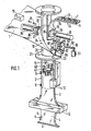
- FIG. 1 shows a device for shaping, filling and closing tubular bag packs with a removal nozzle in a diagrammatic representation
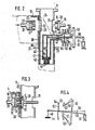
- FIG. 2 shows the molding and filling device of the device according to FIG. 1 in cross section
- FIG. 3 shows part of the device according to FIG. 2 in cross section in a second working position
- Figure 4 shows the actuating mechanism of the filling device in a simplified representation.
- a packaging material web 1 that runs from a supply roll (not shown) and is heat-sealably coated on at least one side is guided over a shaping shoulder 10, which forms it around a shaping tube 11 to form a tube 2.
- a pair of longitudinal seam sealing jaws 12 welds the two inner edges of the packaging material web 1, which are placed against the inner side, to form a longitudinal seam 3.
- a fastening device 15 which, when the packaging material web 1 is at a standstill, fastens a removal nozzle 5 to the packaging material web 1 by heat sealing.
- the sample nozzles 5, which are formed from a thermoplastic, are welded to their flange 6 on the inside of the packaging material web, their two tubes 7 through holes 8 in the packaging material web 1 protrude, which have been punched into the packaging material web 1 by a punching device 16 in front of the shaping shoulder 10.
- the shaped shoulder 10 consists of a guide or pipe socket 20 surrounding the shaped pipe 11 with a narrow gap, with a fastening flange 21 and a collar 22 surrounding the upper inlet opening, via which and the deflecting edge 24 which is common to the inside of the pipe socket 20, the packaging material web 1 during molding of hose 2 runs.
- the upper inlet opening of the pipe socket 20 is inclined to the longitudinal axis, so that the collar 22 drops in the running direction of the packaging material web 1 from its apex on the inlet side of the packaging material web to the other side.
- the pipe socket 20 and the flange 21 have a gap 23 through which the protruding longitudinal edges when the packaging material web 1 or the hose 2 is pulled forward to run.
- the fastening device 15 which has a sealing stamp 26 with a heating device 27 and a support 28 designed as a counter-stamp for the removal nozzle 5, is arranged in the upper region of the shaped shoulder 10, its common effective surface being below the crown of the collar 22 (FIG. 3).
- the sealing stamp 26 is transversely on the inlet side of the packaging material web 1 and the carrier 28 on the side of the inlet opening of the shaped shoulder 10 whose longitudinal axis is arranged displaceably.
- recesses 29, 30, 31 are provided in the pipe socket 20 and in the molded tube 11, which are aligned with one another and are adapted to the shape of the sealing die 26 and the carrier 28 and their movement paths.
- a feed device 33 with a guide groove 34 is arranged above the fastening device 15, the end 35 of which lies between the molded tube 11 and the end face of the support 28 in its retracted position ( Figure 1).
- the sealing stamp 26 and the carrier 28 are each provided connected to a hydraulic or pneumatic actuating cylinder 36.
- the sealing stamp 26 and the carrier 28 are moved against one another, the carrier 28 taking over a provided extraction nozzle 5 at the end 35 of the feed channel 34 and transporting it against the packaging material web 1, the two tubes 7 of the extraction nozzle 5 being the holes 8 pierce the positioned packaging material web 1 and finally the flange 6 comes to rest on the inside of the packaging material web 1, so that when the sealing die 26 is also delivered, the flange 6 of the removal nozzle 5 is pressed with the packaging material web 1 and sealed by transferring heat from the sealing die 26 to the latter will ( Figure 3). After a certain pressing time, the carrier 28 and the sealing die 26 are withdrawn again from the active position into their starting position.
- the sealing stamp 26 In order to receive the tubes 7 of the socket 5 during the sealing, the sealing stamp 26 has two correspondingly arranged blind bores 37 in its end face. To hold a removal nozzle 5 during the transfer 28 suction bores, not shown, are arranged in the end face of the carrier; but it can also be used in the end face pins which engage in the tube 7 of the nozzle.
- a filling pipe 40 is arranged coaxially in the molded tube 11, at the lower end of which a metering valve 41 is arranged.
- This metering valve 41 has a valve seat plate 42 with a plurality of downwardly extending outlet tubes 43 and a valve plate 44 which can be moved in the filling pipe 40 against the valve seat plate 42.
- the upper end of the filling pipe 40 lies slightly below the working area of the fastening device 15 and is connected there to a feed pipe 46 which extends through the molded pipe 11.
- valve plate 44 is temporarily lifted off the valve seat plate 42 in order to dose the individual quantities of filling material.
- the valve plate 44 is fastened to a rod 48 which extends in the filling pipe 40 to the height of the feed connector 46 and whose upper end is articulated at one end of a lever 50.
- an actuating cylinder 51 is articulated at its other end.
- the opening of the feed pipe 46 opposite the filling pipe 40 is closed with a flexible wall in the form of a membrane 52, which is braced with an annular flange 53 with a flange 54 at the end of the feed pipe 46.
- the membrane 52 is also tightly connected to the lever 50.
- the lever 50 In order to pivot the lever 50 about an axis which runs through the center of the membrane 52, the lever 50 has two cross arms 56, 57 on its arm 55 extending outside the feed connector 46.
- the ends of the cross arms 56, 57 are on links 58, 59 articulated, which are mounted in fixed bearings 60, 61 on the ring flange 53.
- the two links 58, 59 assume a position in which their elongated longitudinal axes intersect at the center of the membrane 52 ( Figure 2).
- the lever 50 is pivoted in a clockwise direction, the lever 50 being pivoted about an axis passing through the center of the membrane 52 by the arrangement of the links 58, 59 described above, and the valve plate 44 being lifted off the valve seat plate 42 .
- valve plate 44 is lifted from the valve seat plate 42 while the hose 2 is being pulled forward, so that the liquid can flow out of the filling pipe 40 and through the outlet tubes 43 into the clamped end of the hose 2 .
Landscapes
- Engineering & Computer Science (AREA)
- Mechanical Engineering (AREA)
- Containers And Plastic Fillers For Packaging (AREA)
Abstract
Eine Vorrichtung zum Herstellen von Schlauchbeutelpackungen (4) ist mit einer Einrichtung zum Befestigen von Entnahmestutzen (5) ausgerüstet. Die Befestigungseinrichtung (15) hat einen Träger (28) zum Zuführen jeweils eines Entnahmestutzens zur Innenseite des aus einem Packstoffstreifen (1) gebildeten Schlauches (2) und einen Siegelstempel (26), die im Bereich eines Schlauchformers (10) gegeneinander verschiebbar angeordnet sind. Der Träger (28), der jeweils einen Entnahmestutzen von einer Zuführeinrichtung (33) übernimmt, greift in die Eintrittsöffnung des Schlauchformers, wo hingegen der Siegelstempel von der Gegenseite aus gegen die Außenseite des Schlauches unterhalb des Scheitels eines Kragens (22) des Schlauchformers bewegbar ist.
Description
- Die Erfindung geht aus von einer Vorrichtung zum Herstellen von Beutelpackungen mit Entnahmestutzen nach der Gattung des Anspruchs 1. Es sind schon Vorrichtungen dieser Art bekannt geworden (DE-A-1 536 019, US-A-3 894 481), bei denen der Entnahmestutzen mit seinem Flansch an der Außenseite des Schlauches angesetzt und angesiegelt wird. Abgesehen davon, daß der Rand des Flansches eine Angriffsfläche zum Abreißen des Entnahmestutzens bietet, hat die Befestigung auf der Außenseite der Beutelpackung den Nachteil, daß der Packstoff auch auf seiner Außenseite heißsiegelbar beschichtet sein muß. Ferner hat die bekannte Vorrichtung den Nachteil, daß zum Ansiegeln des Flansches des Entnahmestutzens an den Schlauch eine verhältnismäßig lange Zeitdauer erforderlich ist, da die zum Siegeln erforderliche Wärme durch den dicken Flansch transportiert und nach dem Siegeln wieder abgeführt werden muß.
- Die erfindungsgemäße Vorrichtung mit den kennzeichnenden Merkmalen des Anspruchs 1 hat demgegenüber den Vorteil, daß die Siegelzeit zum Befestigen des Flansches des Entnahmestutzens am Beutelpackstoff die gleiche Dauer hat wie das Siegeln der Längsnaht und der Quernähte des Beutels, so daß eine hohe Ausbringung gewährleistet ist. Ferner ist vorteilhaft, daß die Befestigungseinrichtung an einer Stelle angeordnet ist, in der der Packstoff noch nicht mit dem Füllgut beaufschlagt ist, so daß dieses von der Befestigungseinrichtung unbeeinflußt bleibt. Durch die in den Unteransprüchen aufgeführten Maßnahmen sind vorteilhafte Weiterbildungen und Verbesserungen der im Hauptanspruch angegebenen Vorrichtung möglich.
- Ein Ausführungsbeispiel der Erfindung ist in der Zeichnung dargestellt und in der nachfolgenden Beschreibung näher erläutert. Es zeigen Figur 1 eine Vorrichtung zum Formen, Füllen und Verschließen von Schlauchbeutelpackungen mit Entnahmestutzen in schaubildlicher Darstellung, Figur 2 die Form- und Fülleinrichtung der Vorrichtung nach Figur 1 im Querschnitt, Figur 3 einen Teil der Einrichtung nach Figur 2 im Querschnitt in einer zweiten Arbeitsstellung und Figur 4 den Betätigungsmechanismus der Fülleinrichtung in vereinfachter Darstellung.
- Eine von einer nicht dargestellten Vorratsrolle ablaufende, zumindest einseitig heißsiegelfähig beschichtete Packstoffbahn 1 wird über eine Formschulter 10 geführt, welche sie um ein Formrohr 11 zu einem Schlauch 2 formt. Ein Längsnahtsiegelbackenpaar 12 verschweißt die beiden Innenseite gegen Innenseite gelegten Längsränder der Packstoffbahn 1 zu einer Längsnaht 3. Ein taktweise auf- und abbewegtes Quernahtsiegelbackenpaar 13 teilt den Schlauch 2 nach Einfüllen jeweils einer Füllmenge in einzelne Beutelpackungen 4 ab und zieht den Schlauch 2 um jeweils eine Beutellänge nach unten ab. Im Bereich der Formschulter 10 ist eine Befestigungseinrichtung 15 angeordnet, die beim Stillstand der Packstoffbahn 1 jeweils einen Entnahmestutzen 5 durch Heißsiegeln an der Packstoffbahn 1 befestigt. Die beispielsweise dargestellten Entnahmestutzen 5 haben an einem Flansch 6 je zwei abstehende Röhrchen 7. Die aus einem thermoplastischen Kunststoff geformten Entnahmestutzen 5 werden mit ihrem Flansch 6 auf der Innenseite der Packstoffbahn anliegend mit dieser verschweißt, wobei ihre beiden Röhrchen 7 durch Löcher 8 in der Packstoffbahn 1 ragen, die von einer Stanzeinrichtung 16 vor der Formschulter 10 in die Packstoffbahn 1 eingestanzt worden sind.
- Die Formschulter 10 besteht aus einem das Formrohr 11 mit engem Spalt umgebenden Führungs- oder Rohrstutzen 20 mit einem Befestigungsflansch 21 und aus einem die obere Einlauföffnung umgebenden Kragen 22, über den und dessen mit der Innenseite des Rohrstutzens 20 gemeinsamer Umlenkkante 24 die Packstoffbahn 1 beim Formen des Schlauches 2 läuft. Die obere Eintrittsöffnung des Rohrstutzens 20 verläuft zur Längsachse geneigt, so daß der Kragen 22 in Laufrichtung der Packstoffbahn 1 von seinem Scheitel auf der Zulaufseite der Packstoffbahn zur anderen Seite hin abfällt. An der niederen Stelle des Kragens 22, an der die beiden Längsränder der Packstoffbahn 1 Innenseite gegen Innenseite aufeinander gelegt werden, haben der Rohrstutzen 20 und der Flansch 21 einen Spalt 23, durch den beim Vorziehen der Packstoffbahn 1 bzw. des Schlauches 2 die abstehenden Längsränder laufen.
- Die Befestigungseinrichtung 15, die einen Siegelstempel 26 mit einer Heizeinrichtung 27 und einen als Gegenstempel ausgebildeten Träger 28 für die Entnahmestutzen 5 aufweist, ist im oberen Bereich der Formschulter 10 angeordnet, wobei ihre gemeinsame Wirkfläche unterhalb des Scheitels des Kragens 22 liegt (Figur 3). Der Siegelstempel 26 ist dabei auf der Zulaufseite der Packstoffbahn 1 und der Träger 28 auf der Seite der Eintrittsöffnung der Formschulter 10 quer zu deren Längsachse verschiebbar angeordnet. Zum Erreichen der Packstoffbahn 1 in der Wirkstellung sind im Rohrstutzen 20 und im Formrohr 11 miteinander ausgerichtete, der Form des Siegelstempels 26 und des Trägers 28 sowie deren Bewegungsbahnen angepaßte Ausnehmungen 29, 30, 31 vorgesehen. Zum Zuführen der Entnahmestutzen 5 in den Arbeitsbereich der Befestigungseinrichtung 15, insbesondere vor deren Träger 28, ist oberhalb der Befestigungseinrichtung 15 eine Zuführeinrichtung 33 mit einer Führungsrinne 34 angeordnet, deren Ende 35 zwischen dem Formrohr 11 und der Stirnseite des Trägers 28 in seiner zurückgezogenen Stellung liegt (Figur 1). Zum Hin- und Herbewegen des Siegelstempels 26 und des Trägers 28 zwischen einer Ausgangsstellung, in der die beiden voneinander entfernt sind, und einer Wirkstellung, in der die beiden gegeneinander gepreßt sind (Figur 3), sind der Siegelstempel 26 und der Träger 28 mit je einem hydraulischen oder pneumatischen Betätigungszylinder 36 verbunden. Zum Befestigen eines Entnahmestutzens 5 werden der Siegelstempel 26 und der Träger 28 gegeneinander bewegt, wobei der Träger 28 am Ende 35 der Zuführrinne 34 einen bereitgestellten Entnahmestutzen 5 übernimmt und diesen gegen die Packstoffbahn 1 transportiert, wobei die beiden Röhrchen 7 des Entnahmestutzens 5 die Löcher 8 der positionierten Packstoffbahn 1 durchstoßen und schließlich der Flansch 6 an der Innenseite der Packstoffbahn 1 zur Anlage kommt, so daß bei ebenfalls zugestelltem Siegelstempel 26 der Flansch 6 des Entnahmestutzens 5 mit der Packstoffbahn 1 verpreßt und durch Übertragen von Wärme seitens des Siegelstempels 26 mit dieser versiegelt wird (Figur 3). Nach einer gewissen Preßdauer werden der Träger 28 und der Siegelstempel 26 wieder aus der Wirkstellung in ihre Ausgangsstellung zurückgezogen. Zum Aufnehmen der Röhrchen 7 des Stutzens 5 während des Siegelns hat der Siegelstempel 26 zwei entsprechend angeordnete Sackbohrungen 37 in seiner Stirnseite. Zum Halten eines Entnahmestutzens 5 während des Überführens sind in der Stirnseite des Trägers 28 nicht dargestellte Saugbohrungen angeordnet; es können aber auch in der Stirnseite Stifte eingesetzt sein, die in die Röhrchen 7 des Stutzens eingreifen.
- Das Ansiegeln eines Entnahmestutzens 5 an die Packstoffbahn 1 erfolgt während des Stillstands der Packstoffbahn, währenddessen auch die Längsnaht 3 vom Längsnahtsiegelbackenpaar 12 gebildet wird, und das Quernahtsiegelbackenpaar 13 von einer unteren Stellung in eine obere Ausgangsstellung zurückkehrt. Nach dem Schließen des Quernahtsiegelbackenpaares 13 wird dieses nach unten bewegt, so daß es den Schlauch 2 und die Packstoffbahn 1 um eine Beutellänge vorzieht, wobei die vom Schlauch 2 nach außen abstehenden Röhrchen 7 des Entnahmestutzens durch einen Längsschlitz 38 im Rohrstutzen 20 der Formschulter 10 unterhalb der Ausnehmung 29 gezogen werden und wobei das Quernahtsiegelbackenpaar 13 eine Beutelpackung 4 durch Anbringen von Quernähten 9 vom Schlauch 2 abteilt.
- Zum Einfüllen jeweils einer Menge eines flüssigen Füllguts in die Beutelpackungen 4 ist im Formrohr 11 ein Füllrohr 40 gleichachsig angeordnet, an dessen unterem Ende ein Dosierventil 41 angeordnet ist. Dieses Dosierventil 41 weist eine Ventilsitzplatte 42 mit mehreren nach unten sich erstreckenden Auslaßröhrchen 43 sowie eine im Füllrohr 40 gegen die Ventilsitzplatte 42 bewegbare Ventilplatte 44 auf. Das obere Ende des Füllrohrs 40 liegt wenig unterhalb des Arbeitsbereichs der Befestigungseinrichtung 15 und ist dort mit einem das Formrohr 11 quer durchsetzenden Zuführstutzen 46 verbunden. In diesen Zuführstutzen 46 mündet wiederum quer eine Fülleitung 47, durch die das abzufüllende flüssige Gut zugeführt wird.
- Zum Dosieren der einzelnen Füllgutmengen wird die Ventilplatte 44 zeitweise von der Ventilsitzplatte 42 abgehoben. Dazu ist die Ventilplatte 44 an einer Stange 48 befestigt, die sich im Füllrohr 40 bis zur Höhe des Zuführstutzens 46 erstreckt und deren oberes Ende an einem Ende eines Hebels 50 angelenkt ist. Zum Betätigen des Hebels 50 ist an dessen anderem Ende ein Stellzylinder 51 angelenkt.
- Die dem Füllrohr 40 gegenüberliegende Öffnung des Zuführstutzens 46 ist mit einer biegsamen Wand in Form einer Membran 52 verschlossen, die mit einem Ringflansch 53 mit einem Flansch 54 am Ende des Zuführstutzens 46 verspannt ist. In ihrer Mitte ist die Membran 52 ebenfalls dicht mit dem Hebel 50 verbunden. Zum Schwenken des Hebels 50 um eine Achse, die durch die Mitte der Membran 52 verläuft, hat der Hebel 50 an seinem sich außerhalb des Zuführstutzens 46 erstrekkenden Arm 55 zwei Querarme 56, 57. Die Enden der Querarme 56, 57 sind an Lenkern 58, 59 angelenkt, die in ortsfesten Lagern 60, 61 am Ringflansch 53 gelagert sind. In einer Stellung, und zwar in der Schließstellung des Dosierventils 41 nehmen die beiden Lenker 58, 59 eine Lage ein, in der ihre verlängerten Längsachsen einander im Mittelpunkt der Membran 52 schneiden (Figure 2). Durch eine Stellbewegung des Stellzylinders 51 wird der Hebel 50 im Uhrzeigersinn verschwenkt, wobei durch die beschriebene Anordnung der Lenker 58, 59 der Hebel 50 um eine durch die Mitte der Membran 52 gehende Achse geschwenkt wird und wobei die Ventilplatte 44 von der Ventilsitzplatte 42 abgehoben wird. Zum Einfüllen jeweils einer Flüssigkeitsmenge in das Ende des Schlauches 2 wird die Ventilplatte 44 von der Ventilsitzplatte 42 jeweils während des Vorziehens des Schlauches 2 gehoben, so daß die Flüssigkeit aus dem Füllrohr 40 und durch die Auslaßröhrchen 43 in das abgeklemmte Ende des Schlauches 2 einströmen kann.
- Ergänzend wird darauf hingewiesen, daß mit der oben beschriebenen Befestigungseinrichtung bei entsprechender Anpassung des Trägers und des Stempels auch anders geformte Entnahmestutzen am Schlauch bzw. den geformten Beutelpackungen angebracht werden können.
Claims (5)
1. Vorrichtung zum Herstellen von Beutelpackungen (4) aus einem heißsiegelbaren Packstoffstreifen (1) mit einem den Packstoffstreifen zu einem Schlauch (2) umformenden Schlauchformer (10), der an einem hohlen, den Schlauch führenden Führungsstutzen (20) einen schrägen Kragen (22) mit einer Eintrittsöffnung hat, mit einer den Schlauch absatzweise vorziehenden Vorzugeinrichtung (13), mit einer die Längsränder des Packstoffstreifens verbindenden Längsnahtsiegeleinrichtung (12), mit einer den Schlauch nach dem Einbringen von Füllgut in einzelne Beutelpackungen unterteilenden Quersiegeleinrichtungen (13) und mit einer Einrichtung(15) zum Befestigen von Entnahmestutzen (5) am Schlauch, die einen jeweils einen Saugstutzen von einer Zuführeinrichtung (33) übernehmenden und an den Schlauch überbringenden Träger (28) aufweist, dadurch gekennzeichnet, daß die Befestigungseinrichtung (15) im Bereich des Schlauchformers (10) angeordnet ist, daß der Träger (28) in die Eintrittsöffnung des Kragens (22) des Schlauchformers gegen die Innenseite des Schlauchs (2) bewegbar ist, daß die Zuführeinrichtung (33) vor der Eintrittsöffnung des Schlauchformers endet, und daß die Befestigungseinrichtung eine Siegeleinrichtung (26, 27) hat, die den Entnahmestutzen (5) mit der Innenseite des Schlauches versiegelt.
2. Vorrichtung nach Anspruch 1, dadurch gekennzeichnet, daß die Siegeleinrichtung (27) in einem Stempel (26) integriert ist, der in Ausrichtung zum Träger (28) unterhalb des Scheitels des Kragens (22) des Schlauchformers (10) angeordnet ist.
3. Vorrichtung nach Anspruch 2, dadurch gekennzeichnet, daß der Führungsstutzen (20) des Schlauchformers (10) in Deckung mit dem Stempel (26) eine Ausnehmung (29) hat, durch die der Stempel (26) gegen die Außenseite des zu einem Schlauch (2) geformten Packstoffstreifens (1) führbar ist.
4. Vorrichtung nach Anspruch 3, dadurch gekennzeichnet, daß der Stempel (26) von außen gegen den vom Träger (28) abgestützten Schlauch (2) preßbar ist.
5. Vorrichtung nach einem der Ansprüche 1 bis 4, dadurch gekennzeichnet, daß im Führungsstutzen (20) des Schlauchformers (10) ein Formrohr (11) angeordnet ist, um das der Packstoffstreifen (1) zu einem Schlauch (2) geformt wird, und daß das Formrohr in Ausrichtung zum Träger (28) und zum Stempel (26) Ausnehmungen (30, 31) hat.
Applications Claiming Priority (2)
| Application Number | Priority Date | Filing Date | Title |
|---|---|---|---|
| DE19863612196 DE3612196A1 (de) | 1986-04-11 | 1986-04-11 | Vorrichtung zum herstellen von beutelpackungen mit entnahmestutzen |
| DE3612196 | 1986-04-11 |
Publications (2)
| Publication Number | Publication Date |
|---|---|
| EP0240695A2 true EP0240695A2 (de) | 1987-10-14 |
| EP0240695A3 EP0240695A3 (de) | 1988-12-21 |
Family
ID=6298462
Family Applications (1)
| Application Number | Title | Priority Date | Filing Date |
|---|---|---|---|
| EP19870102776 Withdrawn EP0240695A3 (de) | 1986-04-11 | 1987-02-26 | Vorrichtung zum Herstellen von Beutelpackungen mit Entnahmestutzen |
Country Status (4)
| Country | Link |
|---|---|
| US (1) | US4709528A (de) |
| EP (1) | EP0240695A3 (de) |
| JP (1) | JPS62251309A (de) |
| DE (1) | DE3612196A1 (de) |
Cited By (6)
| Publication number | Priority date | Publication date | Assignee | Title |
|---|---|---|---|---|
| EP0304479B1 (de) * | 1987-03-09 | 1993-06-09 | BAXTER INTERNATIONAL INC. (a Delaware corporation) | Vorrichtung zum befestigen von füll- oder entleerelementen auf fortlaufenden folienbahnen |
| FR2696991A1 (fr) * | 1992-10-16 | 1994-04-22 | Socar | Procédé et chaîne pour la fabrication d'une outre pour produit liquide, et pour le remplissage et la mise en place de l'outre dans une caisse de distribution. |
| EP0693426A1 (de) * | 1993-07-01 | 1996-01-24 | Elopak Systems Ag | Vorrichtung zum Anbringen einer Aussgiesstülle an einem Behälter |
| GB2293134A (en) * | 1994-11-10 | 1996-03-20 | Grace W R & Co | Supply of fitments on a flexible tape |
| DE19504045A1 (de) * | 1995-02-08 | 1996-08-14 | Rovema Gmbh | Beutel aus einer schweißbaren Kunststoffolie und Verfahren zur Herstellung des Beutels |
| EP1501736A4 (de) * | 2002-04-27 | 2011-05-25 | Smart Bottle Inc | Flexible faltenflasche mit ansatz und herstellungsverfahren |
Families Citing this family (31)
| Publication number | Priority date | Publication date | Assignee | Title |
|---|---|---|---|---|
| US4924655A (en) * | 1987-06-29 | 1990-05-15 | Baxter Travenol Laboratories, Inc. | Film guide system |
| US5014493A (en) * | 1988-06-08 | 1991-05-14 | Bemis Company, Inc. | Form-fill-seal packaging |
| JPH07110648B2 (ja) * | 1988-07-26 | 1995-11-29 | 富士写真フイルム株式会社 | 処理液ポッド製造装置 |
| US5024645A (en) * | 1989-05-26 | 1991-06-18 | Baxter International Inc. | Apparatus for positioning a port in an aperture in a web of film |
| US5058360A (en) * | 1990-04-04 | 1991-10-22 | Toppan Printing Co., Ltd. | Filling and sealing apparatus for fluid containing package |
| US5046300A (en) * | 1990-10-19 | 1991-09-10 | Reynolds Consumer Products, Inc. | Method and apparatus for forming a reclosable package |
| US5127208A (en) * | 1990-10-19 | 1992-07-07 | Reynolds Consumer Products Inc. | Method and apparatus for forming a reclosable package |
| DE19546846A1 (de) * | 1995-12-15 | 1997-07-03 | Tetra Laval Holdings & Finance | Verfahren zur Herstellung einer mit Fließmittel gefüllten Beutelpackung |
| US6182426B1 (en) * | 1998-10-19 | 2001-02-06 | Liqui-Box Corporation | Vertical form, fill, seal machine and methods |
| US6041575A (en) * | 1998-11-03 | 2000-03-28 | Exact Packaging, Inc. | Method and apparatus for applying article to interior surface of flexible package |
| US6360513B1 (en) | 1999-05-11 | 2002-03-26 | Sargento Foods Inc. | Resealable bag for filling with food product(s) and method |
| US7207153B1 (en) | 1999-12-02 | 2007-04-24 | Illinois Tool Works Inc. | Method for attaching fitment at longitudinal fin seal and package resulting therefrom |
| US6588177B1 (en) | 2002-02-04 | 2003-07-08 | Reynolds Consumer Products, Inc. | Method and apparatus for forming a reclosable package |
| US20030196411A1 (en) * | 2002-04-19 | 2003-10-23 | Schroeder Alfred A. | Flexible packaging |
| JP2003335302A (ja) * | 2002-05-15 | 2003-11-25 | Kyoraku Co Ltd | 二重フィルムを使用した製袋充填方法 |
| US20040123883A1 (en) * | 2002-09-19 | 2004-07-01 | Afp Advanced Food Products Llc | Method and apparatus for producing fused tube on bag and bag produced thereby |
| US6968669B2 (en) * | 2002-11-06 | 2005-11-29 | Lancer Partnership Ltd. | Flexible packaging |
| US7770360B2 (en) * | 2005-12-05 | 2010-08-10 | Ds Smith Plastics Limited | Form fill and seal container |
| US8430262B2 (en) | 2008-09-12 | 2013-04-30 | Eco.Logic Brands Inc. | Containers for holding materials |
| WO2013036695A1 (en) | 2011-09-09 | 2013-03-14 | Eco. Logic Brands | Containers for holding materials |
| KR101310488B1 (ko) * | 2009-04-10 | 2013-09-24 | 오리히로엔지니아링구 가부시키가이샤 | 무균 충전 포장 기계 및 무균 충전 포장 방법 |
| US8234840B2 (en) * | 2009-05-15 | 2012-08-07 | Winpak Lane, Inc. | Form, fill, and seal system |
| US8375686B2 (en) * | 2009-12-22 | 2013-02-19 | Cryovac, Inc. | Aseptic packaging system, packaging process and package with external fitment |
| US8387348B2 (en) * | 2009-12-22 | 2013-03-05 | Cryovac, Inc. | Aseptic packaging system, packaging process and package with internal fitment |
| AU2011224353B2 (en) | 2010-03-10 | 2016-06-30 | Eco.Logic Brands Inc. | Containers for holding materials |
| USD645755S1 (en) | 2010-03-10 | 2011-09-27 | Eco.Logic Brands Inc. | Container |
| US8663419B2 (en) | 2010-11-30 | 2014-03-04 | Ecologic | Manual container assembly and liner integration fixture for pulp-molded shell with polymer liner container systems |
| USD720227S1 (en) | 2012-09-06 | 2014-12-30 | Eco.Logic Brands Inc. | Container for holding materials |
| EP3038936B1 (de) | 2013-10-02 | 2024-08-07 | Eco.logic Brands Inc. | Behälter für partikelförmige materialien |
| US11952192B2 (en) * | 2018-09-26 | 2024-04-09 | Robert C. Kelly | Standing pouch with cap on folded edge |
| IT201900022362A1 (it) * | 2019-11-28 | 2021-05-28 | Ica Spa | Sistema e metodo per la produzione di confezioni munite di un sistema di chiusura reversibile |
Family Cites Families (9)
| Publication number | Priority date | Publication date | Assignee | Title |
|---|---|---|---|---|
| US3244576A (en) * | 1963-02-04 | 1966-04-05 | Thermoplastic Ind Inc | Apparatus for manufacturing flexible bags with nozzle |
| GB1378152A (en) * | 1971-04-30 | 1974-12-18 | Agfa Gevaert | Rigid paperboard container |
| US3894381A (en) * | 1973-06-21 | 1975-07-15 | Inpaco | Method and means for attaching fitments to a bag or pouch on a packaging machine |
| IT1027681B (it) * | 1973-12-20 | 1978-12-20 | A C I Operations | Processo et apparecchiatura perfezionati per fabbricare sacchetti sigillati per il contenimento di liquidi |
| US4246062A (en) * | 1979-03-26 | 1981-01-20 | Christine William C | Apparatus for attaching a fitment to a pouch |
| US4512136A (en) * | 1982-08-23 | 1985-04-23 | Trinity Associates, A Partnership Of The State Of Pennsylvania | Fitment attachment methods in horizontal form/fill/seal machines |
| AU559751B2 (en) * | 1982-10-18 | 1987-03-19 | Unitika Ltd. | Filling bags with cap bodies |
| IT1171800B (it) * | 1983-11-14 | 1987-06-10 | Bieffe Spa | Sistema e apparecchiatura per la formatura ed il riempimento di sacche flessibili sterilizzabili |
| US4603536A (en) * | 1985-02-01 | 1986-08-05 | Societe D'etude Et D'application Industrielle De Brevets | Apparatus for forming a web of film into a tubular shape in a form, fill and seal packaging machine |
-
1986
- 1986-04-11 DE DE19863612196 patent/DE3612196A1/de not_active Withdrawn
-
1987
- 1987-01-21 US US07/005,988 patent/US4709528A/en not_active Expired - Fee Related
- 1987-02-26 EP EP19870102776 patent/EP0240695A3/de not_active Withdrawn
- 1987-04-08 JP JP62084918A patent/JPS62251309A/ja active Pending
Cited By (8)
| Publication number | Priority date | Publication date | Assignee | Title |
|---|---|---|---|---|
| EP0304479B1 (de) * | 1987-03-09 | 1993-06-09 | BAXTER INTERNATIONAL INC. (a Delaware corporation) | Vorrichtung zum befestigen von füll- oder entleerelementen auf fortlaufenden folienbahnen |
| FR2696991A1 (fr) * | 1992-10-16 | 1994-04-22 | Socar | Procédé et chaîne pour la fabrication d'une outre pour produit liquide, et pour le remplissage et la mise en place de l'outre dans une caisse de distribution. |
| WO1994008851A1 (fr) * | 1992-10-16 | 1994-04-28 | Societe Continentale Du Carton Ondule Socar | Procede et chaine pour la fabrication d'outres |
| EP0693426A1 (de) * | 1993-07-01 | 1996-01-24 | Elopak Systems Ag | Vorrichtung zum Anbringen einer Aussgiesstülle an einem Behälter |
| GB2293134A (en) * | 1994-11-10 | 1996-03-20 | Grace W R & Co | Supply of fitments on a flexible tape |
| DE19504045A1 (de) * | 1995-02-08 | 1996-08-14 | Rovema Gmbh | Beutel aus einer schweißbaren Kunststoffolie und Verfahren zur Herstellung des Beutels |
| DE19504045C2 (de) * | 1995-02-08 | 2003-03-20 | Rovema Gmbh | Beutel aus einer schweißbaren Kunststoffolie und Verfahren zur Herstellung des Beutels |
| EP1501736A4 (de) * | 2002-04-27 | 2011-05-25 | Smart Bottle Inc | Flexible faltenflasche mit ansatz und herstellungsverfahren |
Also Published As
| Publication number | Publication date |
|---|---|
| JPS62251309A (ja) | 1987-11-02 |
| DE3612196A1 (de) | 1987-10-22 |
| EP0240695A3 (de) | 1988-12-21 |
| US4709528A (en) | 1987-12-01 |
Similar Documents
| Publication | Publication Date | Title |
|---|---|---|
| EP0240695A2 (de) | Vorrichtung zum Herstellen von Beutelpackungen mit Entnahmestutzen | |
| DE69900236T2 (de) | Verfahren und Maschine zur Herstellung von Beuteln mit einem transversalen Reissverschluss | |
| DE3905605C2 (de) | Verfahren und Vorrichtung zum Herstellen, Füllen und Verschließen von Beuteln | |
| DE69300281T2 (de) | Biegsamer behälter, verfahren und vorrichtung zu seiner herstellung. | |
| EP0240694A2 (de) | Vorrichtung zum Herstellen von mit Flüssigkeit gefüllten Beutelpackungen | |
| DE10327646B4 (de) | Vorrichtung zur Bildung eines Leimprofils für Kreuzbodensäcke | |
| DE1803906B2 (de) | Kartonaufrichtevorrichtung | |
| DE1056953B (de) | Behaelter fuer Fluessigkeiten aus duennem, elastischem, verschweissbarem Material sowie Verfahren und Schweissbacke zur Herstellung solcher Behaelter | |
| DE3309531C2 (de) | Absackstutzen zum Abfüllen staubiger Produkte in oben offene Säcke | |
| DE2852022C2 (de) | Vorrichtung zum Aufspreizen und Anlegen von Seitenfaltensäcken an den Füllstutzen einer Füllstation | |
| DE2511937A1 (de) | Vorrichtung zum herstellen von aus aussenbehaelter und futterbeutel bestehenden verpackungen | |
| DE10330852A1 (de) | Vertikale Schlauchbeutelmaschine | |
| EP1646495A1 (de) | Bodenlegevorrichtung für papiersäcke | |
| DE2608456A1 (de) | Verfahren und vorrichtung zum vollautomatischen befuellen von aus einer kunststoffschlauchfolienbahn beim befuellen hergestellten saecken oder beuteln | |
| DE2157072B2 (de) | Verfahren und Vorrichtung zum kontinuierlichen Herstellen von gefüllten Beuteln oder Tragetaschen aus thermoplastischer Kunststoffolie | |
| DE9115484U1 (de) | Vorrichtung zum Füllen von Faltschachtelbehältern mit Flüssigkeit und Verschließen der Behälter | |
| DE3005931A1 (de) | Verfahren und vorrichtung zum herstellen eines behaelters aus thermoplastischem kunststoff und damit hergestellter behaelter | |
| EP1415912A1 (de) | Formschulter zum Umformen einer Folienbahn | |
| DE3835953C2 (de) | ||
| DE2043281C3 (de) | Maschine zum Einsetzen von dosierten Mengen geschmolzenen thermoplastischen Kunststoffs in Verschlußkapseln o.dgl | |
| AT394696B (de) | Vorrichtung zum fuellen von offenen saecken | |
| DE3138407C2 (de) | Vorrichtung zum Falten der Randbereiche von gefüllten Faltensäcken | |
| DE10234042B4 (de) | Versiegelungseinrichtung, insbesondere an Siegelgeräten zum Verschluß-Versiegeln von zu evakuierenden Verpackungsbeuteln | |
| DE2906827A1 (de) | Vorrichtung zum herstellen von beuteln | |
| AT202071B (de) |
Legal Events
| Date | Code | Title | Description |
|---|---|---|---|
| PUAI | Public reference made under article 153(3) epc to a published international application that has entered the european phase |
Free format text: ORIGINAL CODE: 0009012 |
|
| AK | Designated contracting states |
Kind code of ref document: A2 Designated state(s): CH DE FR GB IT LI SE |
|
| PUAL | Search report despatched |
Free format text: ORIGINAL CODE: 0009013 |
|
| AK | Designated contracting states |
Kind code of ref document: A3 Designated state(s): CH DE FR GB IT LI SE |
|
| STAA | Information on the status of an ep patent application or granted ep patent |
Free format text: STATUS: THE APPLICATION IS DEEMED TO BE WITHDRAWN |
|
| 18D | Application deemed to be withdrawn |
Effective date: 19890622 |
|
| RIN1 | Information on inventor provided before grant (corrected) |
Inventor name: MERKUS, MINNE |