EP0240694A2 - Vorrichtung zum Herstellen von mit Flüssigkeit gefüllten Beutelpackungen - Google Patents
Vorrichtung zum Herstellen von mit Flüssigkeit gefüllten Beutelpackungen Download PDFInfo
- Publication number
- EP0240694A2 EP0240694A2 EP87102775A EP87102775A EP0240694A2 EP 0240694 A2 EP0240694 A2 EP 0240694A2 EP 87102775 A EP87102775 A EP 87102775A EP 87102775 A EP87102775 A EP 87102775A EP 0240694 A2 EP0240694 A2 EP 0240694A2
- Authority
- EP
- European Patent Office
- Prior art keywords
- tube
- filling
- lever
- packaging material
- feed
- Prior art date
- Legal status (The legal status is an assumption and is not a legal conclusion. Google has not performed a legal analysis and makes no representation as to the accuracy of the status listed.)
- Withdrawn
Links
Images

Classifications
-
- B—PERFORMING OPERATIONS; TRANSPORTING
- B65—CONVEYING; PACKING; STORING; HANDLING THIN OR FILAMENTARY MATERIAL
- B65B—MACHINES, APPARATUS OR DEVICES FOR, OR METHODS OF, PACKAGING ARTICLES OR MATERIALS; UNPACKING
- B65B61/00—Auxiliary devices, not otherwise provided for, for operating on sheets, blanks, webs, binding material, containers or packages
- B65B61/18—Auxiliary devices, not otherwise provided for, for operating on sheets, blanks, webs, binding material, containers or packages for making package-opening or unpacking elements
- B65B61/186—Auxiliary devices, not otherwise provided for, for operating on sheets, blanks, webs, binding material, containers or packages for making package-opening or unpacking elements by applying or incorporating rigid fittings, e.g. discharge spouts
-
- B—PERFORMING OPERATIONS; TRANSPORTING
- B29—WORKING OF PLASTICS; WORKING OF SUBSTANCES IN A PLASTIC STATE IN GENERAL
- B29C—SHAPING OR JOINING OF PLASTICS; SHAPING OF MATERIAL IN A PLASTIC STATE, NOT OTHERWISE PROVIDED FOR; AFTER-TREATMENT OF THE SHAPED PRODUCTS, e.g. REPAIRING
- B29C65/00—Joining or sealing of preformed parts, e.g. welding of plastics materials; Apparatus therefor
- B29C65/02—Joining or sealing of preformed parts, e.g. welding of plastics materials; Apparatus therefor by heating, with or without pressure
- B29C65/18—Joining or sealing of preformed parts, e.g. welding of plastics materials; Apparatus therefor by heating, with or without pressure using heated tools
-
- B—PERFORMING OPERATIONS; TRANSPORTING
- B29—WORKING OF PLASTICS; WORKING OF SUBSTANCES IN A PLASTIC STATE IN GENERAL
- B29C—SHAPING OR JOINING OF PLASTICS; SHAPING OF MATERIAL IN A PLASTIC STATE, NOT OTHERWISE PROVIDED FOR; AFTER-TREATMENT OF THE SHAPED PRODUCTS, e.g. REPAIRING
- B29C65/00—Joining or sealing of preformed parts, e.g. welding of plastics materials; Apparatus therefor
- B29C65/78—Means for handling the parts to be joined, e.g. for making containers or hollow articles, e.g. means for handling sheets, plates, web-like materials, tubular articles, hollow articles or elements to be joined therewith; Means for discharging the joined articles from the joining apparatus
- B29C65/7841—Holding or clamping means for handling purposes
- B29C65/7847—Holding or clamping means for handling purposes using vacuum to hold at least one of the parts to be joined
-
- B—PERFORMING OPERATIONS; TRANSPORTING
- B29—WORKING OF PLASTICS; WORKING OF SUBSTANCES IN A PLASTIC STATE IN GENERAL
- B29C—SHAPING OR JOINING OF PLASTICS; SHAPING OF MATERIAL IN A PLASTIC STATE, NOT OTHERWISE PROVIDED FOR; AFTER-TREATMENT OF THE SHAPED PRODUCTS, e.g. REPAIRING
- B29C66/00—General aspects of processes or apparatus for joining preformed parts
- B29C66/01—General aspects dealing with the joint area or with the area to be joined
- B29C66/05—Particular design of joint configurations
- B29C66/10—Particular design of joint configurations particular design of the joint cross-sections
- B29C66/11—Joint cross-sections comprising a single joint-segment, i.e. one of the parts to be joined comprising a single joint-segment in the joint cross-section
- B29C66/112—Single lapped joints
-
- B—PERFORMING OPERATIONS; TRANSPORTING
- B29—WORKING OF PLASTICS; WORKING OF SUBSTANCES IN A PLASTIC STATE IN GENERAL
- B29C—SHAPING OR JOINING OF PLASTICS; SHAPING OF MATERIAL IN A PLASTIC STATE, NOT OTHERWISE PROVIDED FOR; AFTER-TREATMENT OF THE SHAPED PRODUCTS, e.g. REPAIRING
- B29C66/00—General aspects of processes or apparatus for joining preformed parts
- B29C66/01—General aspects dealing with the joint area or with the area to be joined
- B29C66/05—Particular design of joint configurations
- B29C66/10—Particular design of joint configurations particular design of the joint cross-sections
- B29C66/13—Single flanged joints; Fin-type joints; Single hem joints; Edge joints; Interpenetrating fingered joints; Other specific particular designs of joint cross-sections not provided for in groups B29C66/11 - B29C66/12
- B29C66/131—Single flanged joints, i.e. one of the parts to be joined being rigid and flanged in the joint area
-
- B—PERFORMING OPERATIONS; TRANSPORTING
- B29—WORKING OF PLASTICS; WORKING OF SUBSTANCES IN A PLASTIC STATE IN GENERAL
- B29C—SHAPING OR JOINING OF PLASTICS; SHAPING OF MATERIAL IN A PLASTIC STATE, NOT OTHERWISE PROVIDED FOR; AFTER-TREATMENT OF THE SHAPED PRODUCTS, e.g. REPAIRING
- B29C66/00—General aspects of processes or apparatus for joining preformed parts
- B29C66/40—General aspects of joining substantially flat articles, e.g. plates, sheets or web-like materials; Making flat seams in tubular or hollow articles; Joining single elements to substantially flat surfaces
- B29C66/47—Joining single elements to sheets, plates or other substantially flat surfaces
- B29C66/474—Joining single elements to sheets, plates or other substantially flat surfaces said single elements being substantially non-flat
- B29C66/4742—Joining single elements to sheets, plates or other substantially flat surfaces said single elements being substantially non-flat said single elements being spouts
- B29C66/47421—Joining single elements to sheets, plates or other substantially flat surfaces said single elements being substantially non-flat said single elements being spouts said spouts comprising flanges
-
- B—PERFORMING OPERATIONS; TRANSPORTING
- B29—WORKING OF PLASTICS; WORKING OF SUBSTANCES IN A PLASTIC STATE IN GENERAL
- B29C—SHAPING OR JOINING OF PLASTICS; SHAPING OF MATERIAL IN A PLASTIC STATE, NOT OTHERWISE PROVIDED FOR; AFTER-TREATMENT OF THE SHAPED PRODUCTS, e.g. REPAIRING
- B29C66/00—General aspects of processes or apparatus for joining preformed parts
- B29C66/40—General aspects of joining substantially flat articles, e.g. plates, sheets or web-like materials; Making flat seams in tubular or hollow articles; Joining single elements to substantially flat surfaces
- B29C66/49—Internally supporting the, e.g. tubular, article during joining
-
- B—PERFORMING OPERATIONS; TRANSPORTING
- B29—WORKING OF PLASTICS; WORKING OF SUBSTANCES IN A PLASTIC STATE IN GENERAL
- B29C—SHAPING OR JOINING OF PLASTICS; SHAPING OF MATERIAL IN A PLASTIC STATE, NOT OTHERWISE PROVIDED FOR; AFTER-TREATMENT OF THE SHAPED PRODUCTS, e.g. REPAIRING
- B29C66/00—General aspects of processes or apparatus for joining preformed parts
- B29C66/80—General aspects of machine operations or constructions and parts thereof
- B29C66/81—General aspects of the pressing elements, i.e. the elements applying pressure on the parts to be joined in the area to be joined, e.g. the welding jaws or clamps
- B29C66/814—General aspects of the pressing elements, i.e. the elements applying pressure on the parts to be joined in the area to be joined, e.g. the welding jaws or clamps characterised by the design of the pressing elements, e.g. of the welding jaws or clamps
- B29C66/8141—General aspects of the pressing elements, i.e. the elements applying pressure on the parts to be joined in the area to be joined, e.g. the welding jaws or clamps characterised by the design of the pressing elements, e.g. of the welding jaws or clamps characterised by the surface geometry of the part of the pressing elements, e.g. welding jaws or clamps, coming into contact with the parts to be joined
- B29C66/81431—General aspects of the pressing elements, i.e. the elements applying pressure on the parts to be joined in the area to be joined, e.g. the welding jaws or clamps characterised by the design of the pressing elements, e.g. of the welding jaws or clamps characterised by the surface geometry of the part of the pressing elements, e.g. welding jaws or clamps, coming into contact with the parts to be joined comprising a single cavity, e.g. a groove
-
- B—PERFORMING OPERATIONS; TRANSPORTING
- B29—WORKING OF PLASTICS; WORKING OF SUBSTANCES IN A PLASTIC STATE IN GENERAL
- B29C—SHAPING OR JOINING OF PLASTICS; SHAPING OF MATERIAL IN A PLASTIC STATE, NOT OTHERWISE PROVIDED FOR; AFTER-TREATMENT OF THE SHAPED PRODUCTS, e.g. REPAIRING
- B29C66/00—General aspects of processes or apparatus for joining preformed parts
- B29C66/80—General aspects of machine operations or constructions and parts thereof
- B29C66/82—Pressure application arrangements, e.g. transmission or actuating mechanisms for joining tools or clamps
- B29C66/824—Actuating mechanisms
- B29C66/8242—Pneumatic or hydraulic drives
-
- B—PERFORMING OPERATIONS; TRANSPORTING
- B29—WORKING OF PLASTICS; WORKING OF SUBSTANCES IN A PLASTIC STATE IN GENERAL
- B29C—SHAPING OR JOINING OF PLASTICS; SHAPING OF MATERIAL IN A PLASTIC STATE, NOT OTHERWISE PROVIDED FOR; AFTER-TREATMENT OF THE SHAPED PRODUCTS, e.g. REPAIRING
- B29C66/00—General aspects of processes or apparatus for joining preformed parts
- B29C66/80—General aspects of machine operations or constructions and parts thereof
- B29C66/83—General aspects of machine operations or constructions and parts thereof characterised by the movement of the joining or pressing tools
- B29C66/832—Reciprocating joining or pressing tools
- B29C66/8322—Joining or pressing tools reciprocating along one axis
- B29C66/83221—Joining or pressing tools reciprocating along one axis cooperating reciprocating tools, each tool reciprocating along one axis
-
- B—PERFORMING OPERATIONS; TRANSPORTING
- B29—WORKING OF PLASTICS; WORKING OF SUBSTANCES IN A PLASTIC STATE IN GENERAL
- B29C—SHAPING OR JOINING OF PLASTICS; SHAPING OF MATERIAL IN A PLASTIC STATE, NOT OTHERWISE PROVIDED FOR; AFTER-TREATMENT OF THE SHAPED PRODUCTS, e.g. REPAIRING
- B29C66/00—General aspects of processes or apparatus for joining preformed parts
- B29C66/80—General aspects of machine operations or constructions and parts thereof
- B29C66/84—Specific machine types or machines suitable for specific applications
- B29C66/849—Packaging machines
-
- B—PERFORMING OPERATIONS; TRANSPORTING
- B65—CONVEYING; PACKING; STORING; HANDLING THIN OR FILAMENTARY MATERIAL
- B65B—MACHINES, APPARATUS OR DEVICES FOR, OR METHODS OF, PACKAGING ARTICLES OR MATERIALS; UNPACKING
- B65B39/00—Nozzles, funnels or guides for introducing articles or materials into containers or wrappers
- B65B39/001—Nozzles, funnels or guides for introducing articles or materials into containers or wrappers with flow cut-off means, e.g. valves
- B65B39/004—Nozzles, funnels or guides for introducing articles or materials into containers or wrappers with flow cut-off means, e.g. valves moving linearly
-
- B—PERFORMING OPERATIONS; TRANSPORTING
- B65—CONVEYING; PACKING; STORING; HANDLING THIN OR FILAMENTARY MATERIAL
- B65B—MACHINES, APPARATUS OR DEVICES FOR, OR METHODS OF, PACKAGING ARTICLES OR MATERIALS; UNPACKING
- B65B9/00—Enclosing successive articles, or quantities of material, e.g. liquids or semiliquids, in flat, folded, or tubular webs of flexible sheet material; Subdividing filled flexible tubes to form packages
- B65B9/10—Enclosing successive articles, or quantities of material, in preformed tubular webs, or in webs formed into tubes around filling nozzles, e.g. extruded tubular webs
- B65B9/20—Enclosing successive articles, or quantities of material, in preformed tubular webs, or in webs formed into tubes around filling nozzles, e.g. extruded tubular webs the webs being formed into tubes in situ around the filling nozzles
- B65B9/2035—Tube guiding means
-
- B—PERFORMING OPERATIONS; TRANSPORTING
- B65—CONVEYING; PACKING; STORING; HANDLING THIN OR FILAMENTARY MATERIAL
- B65B—MACHINES, APPARATUS OR DEVICES FOR, OR METHODS OF, PACKAGING ARTICLES OR MATERIALS; UNPACKING
- B65B9/00—Enclosing successive articles, or quantities of material, e.g. liquids or semiliquids, in flat, folded, or tubular webs of flexible sheet material; Subdividing filled flexible tubes to form packages
- B65B9/10—Enclosing successive articles, or quantities of material, in preformed tubular webs, or in webs formed into tubes around filling nozzles, e.g. extruded tubular webs
- B65B9/20—Enclosing successive articles, or quantities of material, in preformed tubular webs, or in webs formed into tubes around filling nozzles, e.g. extruded tubular webs the webs being formed into tubes in situ around the filling nozzles
- B65B9/213—Enclosing successive articles, or quantities of material, in preformed tubular webs, or in webs formed into tubes around filling nozzles, e.g. extruded tubular webs the webs being formed into tubes in situ around the filling nozzles the web having intermittent motion
-
- B—PERFORMING OPERATIONS; TRANSPORTING
- B29—WORKING OF PLASTICS; WORKING OF SUBSTANCES IN A PLASTIC STATE IN GENERAL
- B29C—SHAPING OR JOINING OF PLASTICS; SHAPING OF MATERIAL IN A PLASTIC STATE, NOT OTHERWISE PROVIDED FOR; AFTER-TREATMENT OF THE SHAPED PRODUCTS, e.g. REPAIRING
- B29C65/00—Joining or sealing of preformed parts, e.g. welding of plastics materials; Apparatus therefor
- B29C65/02—Joining or sealing of preformed parts, e.g. welding of plastics materials; Apparatus therefor by heating, with or without pressure
- B29C65/18—Joining or sealing of preformed parts, e.g. welding of plastics materials; Apparatus therefor by heating, with or without pressure using heated tools
- B29C65/24—Joining or sealing of preformed parts, e.g. welding of plastics materials; Apparatus therefor by heating, with or without pressure using heated tools characterised by the means for heating the tool
- B29C65/30—Electrical means
- B29C65/305—Electrical means involving the use of cartridge heaters
-
- B—PERFORMING OPERATIONS; TRANSPORTING
- B29—WORKING OF PLASTICS; WORKING OF SUBSTANCES IN A PLASTIC STATE IN GENERAL
- B29C—SHAPING OR JOINING OF PLASTICS; SHAPING OF MATERIAL IN A PLASTIC STATE, NOT OTHERWISE PROVIDED FOR; AFTER-TREATMENT OF THE SHAPED PRODUCTS, e.g. REPAIRING
- B29C66/00—General aspects of processes or apparatus for joining preformed parts
- B29C66/01—General aspects dealing with the joint area or with the area to be joined
- B29C66/05—Particular design of joint configurations
- B29C66/10—Particular design of joint configurations particular design of the joint cross-sections
- B29C66/11—Joint cross-sections comprising a single joint-segment, i.e. one of the parts to be joined comprising a single joint-segment in the joint cross-section
- B29C66/112—Single lapped joints
- B29C66/1122—Single lap to lap joints, i.e. overlap joints
-
- B—PERFORMING OPERATIONS; TRANSPORTING
- B29—WORKING OF PLASTICS; WORKING OF SUBSTANCES IN A PLASTIC STATE IN GENERAL
- B29C—SHAPING OR JOINING OF PLASTICS; SHAPING OF MATERIAL IN A PLASTIC STATE, NOT OTHERWISE PROVIDED FOR; AFTER-TREATMENT OF THE SHAPED PRODUCTS, e.g. REPAIRING
- B29C66/00—General aspects of processes or apparatus for joining preformed parts
- B29C66/01—General aspects dealing with the joint area or with the area to be joined
- B29C66/05—Particular design of joint configurations
- B29C66/10—Particular design of joint configurations particular design of the joint cross-sections
- B29C66/13—Single flanged joints; Fin-type joints; Single hem joints; Edge joints; Interpenetrating fingered joints; Other specific particular designs of joint cross-sections not provided for in groups B29C66/11 - B29C66/12
- B29C66/133—Fin-type joints, the parts to be joined being flexible
-
- B—PERFORMING OPERATIONS; TRANSPORTING
- B29—WORKING OF PLASTICS; WORKING OF SUBSTANCES IN A PLASTIC STATE IN GENERAL
- B29C—SHAPING OR JOINING OF PLASTICS; SHAPING OF MATERIAL IN A PLASTIC STATE, NOT OTHERWISE PROVIDED FOR; AFTER-TREATMENT OF THE SHAPED PRODUCTS, e.g. REPAIRING
- B29C66/00—General aspects of processes or apparatus for joining preformed parts
- B29C66/40—General aspects of joining substantially flat articles, e.g. plates, sheets or web-like materials; Making flat seams in tubular or hollow articles; Joining single elements to substantially flat surfaces
- B29C66/41—Joining substantially flat articles ; Making flat seams in tubular or hollow articles
- B29C66/43—Joining a relatively small portion of the surface of said articles
- B29C66/431—Joining the articles to themselves
- B29C66/4312—Joining the articles to themselves for making flat seams in tubular or hollow articles, e.g. transversal seams
-
- B—PERFORMING OPERATIONS; TRANSPORTING
- B29—WORKING OF PLASTICS; WORKING OF SUBSTANCES IN A PLASTIC STATE IN GENERAL
- B29C—SHAPING OR JOINING OF PLASTICS; SHAPING OF MATERIAL IN A PLASTIC STATE, NOT OTHERWISE PROVIDED FOR; AFTER-TREATMENT OF THE SHAPED PRODUCTS, e.g. REPAIRING
- B29C66/00—General aspects of processes or apparatus for joining preformed parts
- B29C66/40—General aspects of joining substantially flat articles, e.g. plates, sheets or web-like materials; Making flat seams in tubular or hollow articles; Joining single elements to substantially flat surfaces
- B29C66/41—Joining substantially flat articles ; Making flat seams in tubular or hollow articles
- B29C66/43—Joining a relatively small portion of the surface of said articles
- B29C66/432—Joining a relatively small portion of the surface of said articles for making tubular articles or closed loops, e.g. by joining several sheets ; for making hollow articles or hollow preforms
- B29C66/4322—Joining a relatively small portion of the surface of said articles for making tubular articles or closed loops, e.g. by joining several sheets ; for making hollow articles or hollow preforms by joining a single sheet to itself
-
- B—PERFORMING OPERATIONS; TRANSPORTING
- B29—WORKING OF PLASTICS; WORKING OF SUBSTANCES IN A PLASTIC STATE IN GENERAL
- B29C—SHAPING OR JOINING OF PLASTICS; SHAPING OF MATERIAL IN A PLASTIC STATE, NOT OTHERWISE PROVIDED FOR; AFTER-TREATMENT OF THE SHAPED PRODUCTS, e.g. REPAIRING
- B29C66/00—General aspects of processes or apparatus for joining preformed parts
- B29C66/50—General aspects of joining tubular articles; General aspects of joining long products, i.e. bars or profiled elements; General aspects of joining single elements to tubular articles, hollow articles or bars; General aspects of joining several hollow-preforms to form hollow or tubular articles
- B29C66/51—Joining tubular articles, profiled elements or bars; Joining single elements to tubular articles, hollow articles or bars; Joining several hollow-preforms to form hollow or tubular articles
- B29C66/53—Joining single elements to tubular articles, hollow articles or bars
- B29C66/532—Joining single elements to the wall of tubular articles, hollow articles or bars
- B29C66/5324—Joining single elements to the wall of tubular articles, hollow articles or bars said single elements being substantially annular, i.e. of finite length
- B29C66/53245—Joining single elements to the wall of tubular articles, hollow articles or bars said single elements being substantially annular, i.e. of finite length said articles being hollow
- B29C66/53246—Joining single elements to the wall of tubular articles, hollow articles or bars said single elements being substantially annular, i.e. of finite length said articles being hollow said single elements being spouts, e.g. joining spouts to containers
- B29C66/53247—Joining single elements to the wall of tubular articles, hollow articles or bars said single elements being substantially annular, i.e. of finite length said articles being hollow said single elements being spouts, e.g. joining spouts to containers said spouts comprising flanges
-
- B—PERFORMING OPERATIONS; TRANSPORTING
- B29—WORKING OF PLASTICS; WORKING OF SUBSTANCES IN A PLASTIC STATE IN GENERAL
- B29C—SHAPING OR JOINING OF PLASTICS; SHAPING OF MATERIAL IN A PLASTIC STATE, NOT OTHERWISE PROVIDED FOR; AFTER-TREATMENT OF THE SHAPED PRODUCTS, e.g. REPAIRING
- B29C66/00—General aspects of processes or apparatus for joining preformed parts
- B29C66/50—General aspects of joining tubular articles; General aspects of joining long products, i.e. bars or profiled elements; General aspects of joining single elements to tubular articles, hollow articles or bars; General aspects of joining several hollow-preforms to form hollow or tubular articles
- B29C66/61—Joining from or joining on the inside
-
- B—PERFORMING OPERATIONS; TRANSPORTING
- B29—WORKING OF PLASTICS; WORKING OF SUBSTANCES IN A PLASTIC STATE IN GENERAL
- B29C—SHAPING OR JOINING OF PLASTICS; SHAPING OF MATERIAL IN A PLASTIC STATE, NOT OTHERWISE PROVIDED FOR; AFTER-TREATMENT OF THE SHAPED PRODUCTS, e.g. REPAIRING
- B29C66/00—General aspects of processes or apparatus for joining preformed parts
- B29C66/80—General aspects of machine operations or constructions and parts thereof
- B29C66/83—General aspects of machine operations or constructions and parts thereof characterised by the movement of the joining or pressing tools
- B29C66/834—General aspects of machine operations or constructions and parts thereof characterised by the movement of the joining or pressing tools moving with the parts to be joined
- B29C66/8351—Jaws mounted on rollers, cylinders, drums, bands, belts or chains; Flying jaws
- B29C66/83541—Jaws mounted on rollers, cylinders, drums, bands, belts or chains; Flying jaws flying jaws, e.g. jaws mounted on crank mechanisms or following a hand over hand movement
- B29C66/83543—Jaws mounted on rollers, cylinders, drums, bands, belts or chains; Flying jaws flying jaws, e.g. jaws mounted on crank mechanisms or following a hand over hand movement cooperating flying jaws
-
- B—PERFORMING OPERATIONS; TRANSPORTING
- B65—CONVEYING; PACKING; STORING; HANDLING THIN OR FILAMENTARY MATERIAL
- B65B—MACHINES, APPARATUS OR DEVICES FOR, OR METHODS OF, PACKAGING ARTICLES OR MATERIALS; UNPACKING
- B65B39/00—Nozzles, funnels or guides for introducing articles or materials into containers or wrappers
- B65B2039/009—Multiple outlets
Definitions
- the invention is based on a device for producing liquid-filled bag packs according to the preamble of claim 1.
- a device of this type known, for example, from DE-A-2 355 957, the filler neck is connected to the filler tube above the hose former, which is wide protrudes above the hose former, and the actuating rod for the metering valve is connected to an actuating cylinder at the upper end of the filling tube.
- the device according to the invention with the characterizing features of claim 1 has the advantage that there is space for other devices for acting on the packaging material and / or the filling material above the tube former, such as, for example, due to the feed line and the valve actuation in the region of the entry opening of the collar a device for attaching removal nozzles for the contents to the bag packs.
- the measure according to claim 3 is particularly advantageous, with which a wall bushing of the actuating lever with its axis of rotation in the wall is possible without the use of a bearing and an axle journal, so that there are no sealing problems at this point. Furthermore, the bulging and bulging membrane prevents the transfer of turbulence to the filling material. In addition, the membrane is only slightly stressed, so that its durability is very long.
- FIG. 1 shows a device for shaping, filling and closing tubular bag packs with a removal nozzle in a diagrammatic representation
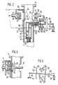
- FIG. 2 shows the molding and filling device of the device according to FIG. 1 in cross section
- FIG. 3 shows a part of the device according to FIG and Figure 4 shows the actuating mechanism of the filling device in a simplified representation.
- a packaging material web 1 that runs from a supply roll (not shown) and is heat-sealably coated on at least one side is guided over a shaping shoulder 10, which forms it around a shaping tube 11 to form a tube 2.
- a pair of longitudinal seam sealing jaws 12 welds the two inner edges of the packaging material web 1, which are placed against the inner side, to form a longitudinal seam 3.
- a fastening device 15 which, when the packaging material web 1 is at a standstill, fastens a removal nozzle 5 to the packaging material web 1 by heat sealing.
- the sample nozzles 5, which are formed from a thermoplastic, are welded to their flange 6 on the inside of the packaging material web, their two tubes 7 through holes 8 in the packaging material web 1 protrude, which have been punched into the packaging material web 1 by a punching device 16 in front of the shaping shoulder 10.
- the shaped shoulder 10 consists of a guide or pipe socket 20 surrounding the shaped tube 11 with a narrow gap, with a fastening flange 21 and a collar 22 surrounding the upper inlet opening, via which and the deflecting edge 24 which is common to the inside of the pipe socket 20, the packaging material web 1 during molding of hose 2 runs.
- the upper inlet opening of the pipe socket 20 is inclined to the longitudinal axis, so that the collar 22 drops in the running direction of the packaging material web 1 from its apex on the inlet side of the packaging material web to the other side.
- the pipe socket 20 and the flange 21 have a gap 23 through which the protruding longitudinal edges when the packaging material web 1 or the hose 2 is pulled forward to run.
- the fastening device 15 which has a sealing stamp 26 with a heating device 27 and a support 28 designed as a counter-stamp for the removal nozzle 5, is arranged in the upper region of the shaped shoulder 10, its common effective surface being below the crown of the collar 22 (FIG. 3).
- the sealing stamp 26 is transversely on the inlet side of the packaging material web 1 and the carrier 28 on the side of the inlet opening of the shaped shoulder 10 whose longitudinal axis is arranged displaceably.
- recesses 29, 30, 31 are provided in the pipe socket 20 and in the shaped pipe 11, which are aligned with one another and are adapted to the shape of the sealing die 26 and the carrier 28 and their movement paths.
- a feed device 33 with a guide groove 34 is arranged above the fastening device 15, the end 35 of which lies between the molded tube 11 and the end face of the support 28 in its retracted position ( Figure 1).
- the sealing stamp 26 and the carrier 28 are each provided connected to a hydraulic or pneumatic actuating cylinder 36.
- the sealing stamp 26 and the carrier 28 are moved against one another, the carrier 28 taking over a provided extraction nozzle 5 at the end 35 of the feed channel 34 and transporting it against the packaging material web 1, the two tubes 7 of the extraction nozzle 5 being the holes 8 pierce the positioned packaging material web 1 and finally the flange 6 comes to rest on the inside of the packaging material web 1, so that when the sealing die 26 is also delivered, the flange 6 of the removal nozzle 5 is pressed with the packaging material web 1 and sealed by transferring heat from the sealing die 26 to the latter will ( Figure 3). After a certain pressing time, the carrier 28 and the sealing die 26 are withdrawn again from the active position into their starting position.
- the sealing stamp 26 In order to receive the tubes 7 of the socket 5 during the sealing, the sealing stamp 26 has two correspondingly arranged blind bores 37 in its end face. To hold a removal nozzle 5 during the transfer 28 suction bores, not shown, are arranged in the end face of the carrier; but it can also be used in the end face pins which engage in the tube 7 of the nozzle.
- a filling pipe 40 is arranged coaxially in the molded tube 11, at the lower end of which a metering valve 41 is arranged.
- This metering valve 41 has a valve seat plate 42 with a plurality of downwardly extending outlet tubes 43 and a valve plate 44 which can be moved in the filling pipe 40 against the valve seat plate 42.
- the upper end of the filling pipe 40 lies slightly below the working area of the fastening device 15 and is connected there to a feed pipe 46 which extends through the molded pipe 11.
- valve plate 44 is temporarily lifted off the valve seat plate 42 in order to dose the individual quantities of filling material.
- the valve plate 44 is fastened to a rod 48 which extends in the filling pipe 40 to the height of the feed connector 46 and whose upper end is articulated at one end of a lever 50.
- an actuating cylinder 51 is articulated at its other end.
- the opening of the feed pipe 46 opposite the filling pipe 40 is closed with a flexible wall in the form of a membrane 52, which is braced with an annular flange 53 with a flange 54 at the end of the feed pipe 46. In the middle, the membrane 52 is also tightly connected to the lever 50.
- the lever 50 In order to pivot the lever 50 about an axis which runs through the center of the membrane 52, the lever 50 has two cross arms 56, 57 on its arm 55 extending outside the feed connector 46. The ends of the cross arms 56, 57 are on links 58, 59 articulated, which are mounted in fixed bearings 60, 61 on the ring flange 53. In one position, namely in the closed position of the metering valve 41, the two links 58, 59 assume a position in which their elongated longitudinal axes intersect at the center of the membrane 52 (FIG. 2).
- the lever 50 By an actuating movement of the actuating cylinder 51, the lever 50 is pivoted clockwise, the lever 50 being pivoted about an axis passing through the center of the membrane 52 by the arrangement of the links 58, 59 described above, and the valve plate 44 being lifted off the valve seat plate 42 .
- the valve plate 44 is lifted from the valve seat plate 42 while the hose 2 is being pulled forward, so that the liquid can flow out of the filling pipe 40 and through the outlet tubes 43 into the clamped end of the hose 2 .
Landscapes
- Engineering & Computer Science (AREA)
- Mechanical Engineering (AREA)
- Physics & Mathematics (AREA)
- Fluid Mechanics (AREA)
- Containers And Plastic Fillers For Packaging (AREA)
- Basic Packing Technique (AREA)
Abstract
Description
- Die Erfindung geht aus von einer Vorrichtung zum Herstellen von mit Flüssigkeit gefüllten Beutelpackungen nach der Gattung des Anspruchs 1. Bei einer beispielsweise aus der DE-A-2 355 957 bekannten Vorrichtung dieser Art ist der Füllstutzen oberhalb des Schlauchformers mit dem Füllrohr verbunden, das weit über den Schlauchformer vorragt, und die Betätigungsstange für das Dosierventil ist mit einem Stellzylinder am oberen Ende des Füllrohrs verbunden.
- Die erfindungsgemäße Vorrichtung mit den kennzeichnenden Merkmalen des Anspruchs 1 hat den Vorteil, daß durch die Füllgutzuleitung und die Ventilbetätigung im Bereich der Eintrittsöffnung des Kragens Platz für andere Einrichtungen zum Einwirken auf den Packstoff und/oder das Füllgut oberhalb des Schlauchformers zur Verfügung steht, wie beispielsweise eine Einrichtung zum Befestigen von Entnahmestutzen für das Füllgut an den Beutelpackungen.
- Durch die in den Uteransprüchen aufgeführten Maßnahmen sind vorteilhafte Weiterbildungen und Verbesserungen der im Anspruch 1 angegebenen Vorrichtung möglich. Besonders vorteilhaft ist die Maßnahme nach Anspruch 3, mit der eine Wanddurchführung des Betätigungshebels mit dessen Drehachse in der Wand jedoch ohne Verwendung eines Lagers und eines Achszapfens möglich ist, so das Dichtigkeitsprobleme an dieser Stelle entfallen. Ferner wird durch die sich ein- und auswölbende Membran ein Übertragen von Turbulenzen auf das Füllgut vermieden. Außerdem wird die Membran nur geringfügig beansprucht, so daß deren Haltbarkeit sehr lang ist.
- Ein Ausführungsbeispiel der Erfindung ist in der Zeichnung dargestellt und in der nachfolgenden Beschreibung näher erläutert. Es zeigen Figur 1 eine Vorrichtung zum Formen, Füllen und Verschließen von Schlauchbeutelpackungen mit Entnahmestutzen in schaubildlicher Darstellung, Figur 2 die Form- und Fülleinrichtung der Vorrichtung nach Figur 1 im Querschnitt, Figur 3 einen Teil der Einrichtung nach Figur 2 im Querschnitt in einer zweiten Arbeitsstellung und Figur 4 den Betätigungsmechanismus der Fülleinrichtung in vereinfachter Darstellung.
- Eine von einer nicht dargestellten Vorratsrolle ablaufende, zumindest einseitig heißsiegelfähig beschichtete Packstoffbahn 1 wird über eine Formschulter 10 geführt, welche sie um ein Formrohr 11 zu einem Schlauch 2 formt. Ein Längsnahtsiegelbackenpaar 12 verschweißt die beiden Innenseite gegen Innenseite gelegten Längsränder der Packstoffbahn 1 zu einer Längsnaht 3. Ein taktweise auf- und abbewegtes Quernahtsiegelbackenpaar 13 teilt den Schlauch 2 nach Einfüllen jeweils einer Füllmenge in einzelne Beutelpackungen 4 ab und zieht den Schlauch 2 um jeweils eine Beutellänge nach unten ab. Im Bereich der Formschulter 10 ist eine Befestigungseinrichtung 15 angeordnet, die beim Stillstand der Packstoffbahn 1 jeweils einen Entnahmestutzen 5 durch Heißsiegeln an der Packstoffbahn 1 befestigt. Die beispielsweise dargestellten Entnahmestutzen 5 haben an einem Flansch 6 je zwei abstehende Röhrchen 7. Die aus einem thermoplastischen Kunststoff geformten Entnahmestutzen 5 werden mit ihrem Flansch 6 auf der Innenseite der Packstoffbahn anliegend mit dieser verschweißt, wobei ihre beiden Röhrchen 7 durch Löcher 8 in der Packstoffbahn 1 ragen, die von einer Stanzeinrichtung 16 vor der Formschulter 10 in die Packstoffbahn 1 eingestanzt worden sind.
- Die Formschulter 10 besteht aus einem das Formrohr 11 mit engem Spalt umgebenden Führungs- oder Rohrstutzen 20 mit einem Befestigangsflansch 21 und aus einem die obere Einlauföffnung umgebenden Kragen 22, über den und dessen mit der Innenseite des Rohrstutzens 20 gemeinsamer Umlenkkante 24 die Packstoffbahn 1 beim Formen des Schlauches 2 läuft. Die obere Eintrittsöffnung des Rohrstutzens 20 verläuft zur Längsachse geneigt, so daß der Kragen 22 in Laufrichtung der Packstoffbahn 1 von seinem Scheitel auf der Zulaufseite der Packstoffbahn zur anderen Seite hin abfällt. An der niederen Stelle des Kragens 22, an der die beiden Längsränder der Packstoffbahn 1 Innenseite gegen Innenseite aufeinander gelegt werden, haben der Rohrstutzen 20 und der Flansch 21 einen Spalt 23, durch den beim Vorziehen der Packstoffbahn 1 bzw. des Schlauches 2 die abstehenden Längsränder laufen.
- Die Befestigungseinrichtung 15, die einen Siegelstempel 26 mit einer Heizeinrichtung 27 und einen als Gegenstempel ausgebildeten Träger 28 für die Entnahmestutzen 5 aufweist, ist im oberen Bereich der Formschulter 10 angeordnet, wobei ihre gemeinsame Wirkfläche unterhalb des Scheitels des Kragens 22 liegt (Figur 3). Der Siegelstempel 26 ist dabei auf der Zulaufseite der Packstoffbahn 1 und der Träger 28 auf der Seite der Eintrittsöffnung der Formschulter 10 quer zu deren Längsachse verschiebbar angeordnet. Zum Erreichen der Packstaffbahn 1 in der Wirkstellung sind im Rohrstutzen 20 und im Formrohr 11 miteinander ausgerichtete, der Form des Siegelstempels 26 und des Trägers 28 sowie deren Bewegungsbahnen angepaßte Ausnehmungen 29, 30, 31 vorgesehen. Zum Zuführen der Entnahmestutzen 5 in den Arbeitsbereich der Befestigungseinrichtung 15, insbesondere vor deren Träger 28, ist oberhalb der Befestigungseinrichtung 15 eine Zuführeinrichtung 33 mit einer Führungsrinne 34 angeordnet, deren Ende 35 zwischen dem Formrohr 11 und der Stirnseite des Träger 28 in seiner zurückgezogenen Stellung liegt (Figur 1). Zum Hin- und Herbewegen des Siegelstempels 26 und des Trägers 28 zwischen einer Ausgangsstellung, in der die beiden voneinander entfernt sind, und einer Wirkstellung, in der die beiden gegeneinander gepreßt sind (Figur 3), sind der Siegelstempel 26 und der Träger 28 mit je einem hydraulischen oder pneumatischen Betätigungszylinder 36 verbunden. Zum Befestigen eines Entnahmestutzens 5 werden der Siegelstempel 26 und der Träger 28 gegeneinander bewegt, wobei der Träger 28 am Ende 35 der Zuführrinne 34 einen bereitgestellten Entnahmestutzen 5 übernimmt und diesen gegen die Packstoffbahn 1 transportiert, wobei die beiden Röhrchen 7 des Entnahmestutzens 5 die Löcher 8 der positionierten Packstoffbahn 1 durchstoßen und schließlich der Flansch 6 an der Innenseite der Packstoffbahn 1 zur Anlage kommt, so daß bei ebenfalls zugestelltem Siegelstempel 26 der Flansch 6 des Entnahmestutzens 5 mit der Packstoffbahn 1 verpreßt und durch Übertragen von Wärme seitens des Siegelstempels 26 mit dieser versiegelt wird (Figur 3). Nach einer gewissen Preßdauer werden der Träger 28 und der Siegelstempel 26 wieder aus der Wirkstellung in ihre Ausgangsstellung zurückgezogen. Zum Aufnehmen der Röhrchen 7 des Stutzens 5 während des Siegelns hat der Siegelstempel 26 zwei entsprechend angeordnete Sackbohrungen 37 in seiner Stirnseite. Zum Halten eines Entnahmestutzens 5 während des Überführens sind in der Stirnseite des Trägers 28 nicht dargestellte Saugbohrungen angeordnet; es können aber auch in der Stirnseite Stifte eingesetzt sein, die in die Röhrchen 7 des Stutzens eingreifen.
- Das Ansiegeln eines Entnahmestutzens 5 an die Packstoffbahn 1 erfolgt während des Stillstands der Packstoffbahn, während dessen auch die Längsnaht 3 vom Längsnahtsiegelbackenpaar 12 gebildet wird, und das Quernahtsiegelbackenpaar 13 von einer unteren Stellung in eine obere Ausgangsstellung zurückkehrt. Nach dem Schließen des Quernaht- siegelbackenpaares 13 wird dieses nach unten bewegt, so daß es den Schlauch 2 und die Packstoffbahn 1 um eine Beutellänge vorzieht, wo- bei die vom Schlauch 2 nach außen abstehenden Röhrchen 7 des Entnah- mestutzens durch einen Längsschlitz 38 im Rohrstutzen 20 der Form- schulter 10 unterhalb der Ausnehmung 29 gezogen werden und wobei das Quernahtsiegelbackenpaar 13 eine Beutelpackung 4 durch Anbringen von Quernähten 9 vom Schlauch 2 abteilt.
- Zum Einfüllen jeweils einer Menge eines flüssigen Füllguts in die Beutelpackungen 4 ist im Formrohr 11 ein Füllrohr 40 gleichachsig angeordnet, an dessen unterem Ende ein Dosierventil 41 angeordnet ist. Dieses Dosierventil 41 weist eine Ventilsitzplatte 42 mit mehreren nach unten sich erstreckenden Auslaßröhrchen 43 sowie eine im Füllrohr 40 gegen die Ventilsitzplatte 42 bewegbare Ventilplatte 44 auf. Das obere Ende des Füllrohrs 40 liegt wenig unterhalb des Arbeitsbereichs der Befestigungseinrichtung 15 und ist dort mit einem das Formrohr 11 quer durchsetzenden Zuführstutzen 46 verbunden. In diesen Zuführstutzen 46 mündet wiederum quer eine Fülleitung 47, durch die das abzufüllende flüssige Gut zugeführt wird.
- Zum Dosieren der einzelnen Füllgutmengen wird die Ventilplatte 44 zeitweise von der Ventilsitzplatte 42 abgehoben. Dazu ist die Ventilplatte 44 an einer Stange 48 befestigt, die sich im Füllrohr 40 bis zur Höhe des Zuführstutzens 46 erstreckt und deren oberes Ende an einem Ende eines Hebels 50 angelenkt ist. Zum Betätigen des Hebels 50 ist an dessen anderem Ende ein Stellzylinder 51 angelenkt. Die dem Füllrohr 40 gegenüberliegende Öffnung des Zuführstutzens 46 ist mit einer biegsamen Wand in Form einer Membran 52 verschlossen, die mit einem Ringflansch 53 mit einem Flansch 54 am Ende des Zuführstutzens 46 verspannt ist. In ihrer Mitte ist die Mebran 52 ebenfalls dicht mit dem Hebel 50 verbunden. Zum Schwenken des Hebels 50 um eine Achse, die durch die Mitte der Membran 52 verläuft, hat der Hebel 50 an seinem sich außerhalb des Zuführstutzens 46 erstrekkenden Arm 55 zwei Querarme 56, 57. Die Enden der Querarme 56, 57 sind an Lenkern 58, 59 angelenkt, die in ortsfesten Lagern 60, 61 am Ringflansch 53 gelagert sind. In einer Stellung, und zwar in der Schließstellung des Dosierventils 41 nehmen die beiden Lenker 58, 59 eine Lage ein, in der ihre verlängerten Längsachsen einander im Mittelpunkt der Membran 52 schneiden (Figur 2). Durch eine Stellbewegung des Stellzylinders 51 wird der Hebel 50 im Uhrzeigersinn verschwenkt, wobei durch die beschriebene Anordnung der Lenker 58, 59 der Hebel 50 um eine durch die Mitte der Membran 52 gehende Achse geschwenkt wird und wobei die Ventilplatte 44 von der Ventilsitzplatte 42 abgehoben wird. Zum Einfüllen jeweils einer Flüssigkeitsmenge in das Ende des Schlauches 2 wird die Ventilplatte 44 von der Ventilsitzplatte 42 jeweils während des Vorziehens des Schlauches 2 gehoben, so daß die Flüssigkeit aus dem Füllrohr 40 und durch die Auslaßröhrchen 43 in das abgeklemmte Ende des Schlauches 2 einströmen kann.
- Ergänzend wird darauf hingewiesen, daß mit der oben beschriebenen Befestigungseinrichtung bei entsprechender Anpassung des Trägers und des Stempels auch anders geformte Entnahmestutzen am Schlauch bzw. den geformten Beutelpackungen angebracht werden können.
Claims (4)
Applications Claiming Priority (2)
| Application Number | Priority Date | Filing Date | Title |
|---|---|---|---|
| DE19863612197 DE3612197A1 (de) | 1986-04-11 | 1986-04-11 | Vorrichtung zum herstellen von mit fluessigkeit gefuellten beutelpackungen |
| DE3612197 | 1986-04-11 |
Publications (2)
| Publication Number | Publication Date |
|---|---|
| EP0240694A2 true EP0240694A2 (de) | 1987-10-14 |
| EP0240694A3 EP0240694A3 (de) | 1988-10-05 |
Family
ID=6298463
Family Applications (1)
| Application Number | Title | Priority Date | Filing Date |
|---|---|---|---|
| EP87102775A Withdrawn EP0240694A3 (de) | 1986-04-11 | 1987-02-26 | Vorrichtung zum Herstellen von mit Flüssigkeit gefüllten Beutelpackungen |
Country Status (4)
| Country | Link |
|---|---|
| US (1) | US4724657A (de) |
| EP (1) | EP0240694A3 (de) |
| JP (1) | JPS62251310A (de) |
| DE (1) | DE3612197A1 (de) |
Cited By (5)
| Publication number | Priority date | Publication date | Assignee | Title |
|---|---|---|---|---|
| WO1995001907A3 (en) * | 1993-07-08 | 1995-03-02 | Unilever Plc | Apparatus and methods for producing packets |
| WO2011147639A1 (de) * | 2010-05-27 | 2011-12-01 | Robert Bosch Gmbh | Verfahren zum anbringen einer öffnungseinrichtung an einem aus flexiblem material bestehenden verpackungsbehälter |
| WO2019115708A1 (en) * | 2017-12-15 | 2019-06-20 | Elopak As | Improved filing device |
| WO2024160902A1 (de) * | 2023-02-02 | 2024-08-08 | Fresenius Medical Care Deutschland Gmbh | Beutelsystem für die peritonealdialyse |
| WO2024160911A1 (de) * | 2023-02-02 | 2024-08-08 | Fresenius Medical Care Deutschland Gmbh | VERFAHREN UND VORRICHTUNG ZUR HERSTELLUNG EINES BEUTELS MIT EINEM STUMPFGESCHWEIßTEN ANSCHLUSS |
Families Citing this family (8)
| Publication number | Priority date | Publication date | Assignee | Title |
|---|---|---|---|---|
| JPH0748486Y2 (ja) * | 1989-09-07 | 1995-11-08 | 呉羽化学工業株式会社 | 包装装置におけるフィルム成形装置 |
| US5273065A (en) * | 1993-03-23 | 1993-12-28 | Taylor Julian S | Large diameter and relatively high pressure relief valve |
| JP2691881B2 (ja) * | 1995-05-31 | 1997-12-17 | 株式会社サンエー化研 | 濾過面を有する逆止弁付き包装袋とその製造装置 |
| DE19609102A1 (de) * | 1996-03-10 | 1997-09-11 | Tetra Laval Holdings & Finance | Vorrichtung zum Abfüllen von Flüssigkeiten in Verpackungen |
| ITBO20040407A1 (it) * | 2004-06-29 | 2004-09-29 | Ica Spa | Dispositivo per dosare l'alimentazione di sostanze granulari scorrevoli |
| DE102006052023A1 (de) * | 2006-11-03 | 2008-05-08 | Poly-Clip System Gmbh & Co. Kg | Abfüllvorrichtung und Verfahren zum Abfüllen von viskosem Füllgut |
| ES2410805T3 (es) * | 2009-03-26 | 2013-07-03 | Nestec S.A. | Un conjunto calentador de accesorios y un método de aplicación de un accesorio |
| DE102023102606A1 (de) | 2023-02-02 | 2024-08-08 | Fresenius Medical Care Deutschland Gmbh | Vorrichtung zur Herstellung und Befüllung eines Beutels mit einem stumpfgeschweißten Anschluss |
Family Cites Families (7)
| Publication number | Priority date | Publication date | Assignee | Title |
|---|---|---|---|---|
| US1624736A (en) * | 1925-02-03 | 1927-04-12 | Gen Electric | Valve |
| US2687740A (en) * | 1951-05-23 | 1954-08-31 | Hermorion Ltd | Device for filling liquids into containers |
| US3282020A (en) * | 1963-08-12 | 1966-11-01 | Deering Milliken Res Corp | Quantity control of liquids for packaging |
| US3831821A (en) * | 1973-04-09 | 1974-08-27 | Thimonnier & Cie | Metering dispenser for flowable material |
| US3916598A (en) * | 1974-10-15 | 1975-11-04 | Du Pont | Synchronized tube forming and filling machine for forming chub packages |
| DE2503547A1 (de) * | 1975-01-29 | 1976-08-05 | Jentsch Hans G | Verfahren und vorrichtung zum sterilen abfuellen von fluessigem, pulverfoermigem, granuloesem oder koernigem fuellgut in behaelter bzw. beutel aus siegelfaehigem material |
| SE437136B (sv) * | 1984-03-08 | 1985-02-11 | Tetra Pak Int | Sett och anordning vid tillverkning och fyllning av forpackningsbehallare |
-
1986
- 1986-04-11 DE DE19863612197 patent/DE3612197A1/de not_active Withdrawn
-
1987
- 1987-02-19 US US07/016,700 patent/US4724657A/en not_active Expired - Fee Related
- 1987-02-26 EP EP87102775A patent/EP0240694A3/de not_active Withdrawn
- 1987-04-08 JP JP62084919A patent/JPS62251310A/ja active Pending
Cited By (10)
| Publication number | Priority date | Publication date | Assignee | Title |
|---|---|---|---|---|
| WO1995001907A3 (en) * | 1993-07-08 | 1995-03-02 | Unilever Plc | Apparatus and methods for producing packets |
| US5548947A (en) * | 1993-07-08 | 1996-08-27 | Thomas J. Lipton Co. | Apparatus and method for producing packets |
| AU693801B2 (en) * | 1993-07-08 | 1998-07-09 | Unilever Plc | Apparatus and methods for producing packets |
| AU695922B2 (en) * | 1993-07-08 | 1998-08-27 | Unilever Plc | Apparatus and methods for producing packets |
| WO2011147639A1 (de) * | 2010-05-27 | 2011-12-01 | Robert Bosch Gmbh | Verfahren zum anbringen einer öffnungseinrichtung an einem aus flexiblem material bestehenden verpackungsbehälter |
| WO2019115708A1 (en) * | 2017-12-15 | 2019-06-20 | Elopak As | Improved filing device |
| CN112105561A (zh) * | 2017-12-15 | 2020-12-18 | 爱洛帕克公司 | 改进的灌装装置 |
| US11597542B2 (en) | 2017-12-15 | 2023-03-07 | Elopak Asa | Filling device |
| WO2024160902A1 (de) * | 2023-02-02 | 2024-08-08 | Fresenius Medical Care Deutschland Gmbh | Beutelsystem für die peritonealdialyse |
| WO2024160911A1 (de) * | 2023-02-02 | 2024-08-08 | Fresenius Medical Care Deutschland Gmbh | VERFAHREN UND VORRICHTUNG ZUR HERSTELLUNG EINES BEUTELS MIT EINEM STUMPFGESCHWEIßTEN ANSCHLUSS |
Also Published As
| Publication number | Publication date |
|---|---|
| JPS62251310A (ja) | 1987-11-02 |
| EP0240694A3 (de) | 1988-10-05 |
| US4724657A (en) | 1988-02-16 |
| DE3612197A1 (de) | 1987-10-22 |
Similar Documents
| Publication | Publication Date | Title |
|---|---|---|
| EP0240695A2 (de) | Vorrichtung zum Herstellen von Beutelpackungen mit Entnahmestutzen | |
| DE69213337T2 (de) | Vorrichtung vom vertikalen Typ, zum Formen, Füllen und Schliessen von flexiblen Verpackungen | |
| DE69000392T2 (de) | Verpackungsmaschine. | |
| EP0240694A2 (de) | Vorrichtung zum Herstellen von mit Flüssigkeit gefüllten Beutelpackungen | |
| CH672767A5 (de) | ||
| DE602005004319T2 (de) | Flexible Verpackung mit einem Zapfhahn für Flüssigkeiten und Verfahren zur Herstellung | |
| DE2852022C2 (de) | Vorrichtung zum Aufspreizen und Anlegen von Seitenfaltensäcken an den Füllstutzen einer Füllstation | |
| EP1495966B1 (de) | Vertikale Schlauchbeutelmaschine | |
| DE2511937A1 (de) | Vorrichtung zum herstellen von aus aussenbehaelter und futterbeutel bestehenden verpackungen | |
| DE3726137C2 (de) | ||
| DE4105452A1 (de) | Vorrichtung zum formen von seitenfaltensaecken oder -beuteln mit falzboden | |
| EP0150292B1 (de) | Vorrichtung zum dosierten Abfüllen von hochviskosem Material | |
| DE3004947A1 (de) | Vorrichtung zur ausbildung des oberen endes eines sacks oder beutels | |
| DE10251072A1 (de) | Formschulter zur Umformung einer Folienbahn | |
| DE10052839A1 (de) | Verfahren und Vorrichtung zur beschleunigten Befüllung von Säcken | |
| DE19629644A1 (de) | Fördereinrichtung für eine pastöse Masse | |
| AT394696B (de) | Vorrichtung zum fuellen von offenen saecken | |
| DE10234042B4 (de) | Versiegelungseinrichtung, insbesondere an Siegelgeräten zum Verschluß-Versiegeln von zu evakuierenden Verpackungsbeuteln | |
| DE2214164A1 (de) | Vorrichtung zum anlegen und fuellen eines oben offenen sackes od. dgl | |
| DE2713409A1 (de) | Vorrichtung zum aufstecken von leeren ventilsaecken auf nebeneinanderliegende fuellrohre einer packmaschine | |
| DE2906827A1 (de) | Vorrichtung zum herstellen von beuteln | |
| DE2147567C3 (de) | Vorrichtung zum Herstellen von Säcken aus einem thermoplastischen Kunststoffschlauch | |
| DE1028038B (de) | Vorrichtung zum Verpacken von fluessigen oder pastenfoermigen Stoffen in Kunststoffbehaelter | |
| AT202071B (de) | ||
| DE1786122C3 (de) | Vorrichtung zum Vereinzeln und Umformen von strangförmig miteinander verbundenen Beuteln in Quaderform |
Legal Events
| Date | Code | Title | Description |
|---|---|---|---|
| PUAI | Public reference made under article 153(3) epc to a published international application that has entered the european phase |
Free format text: ORIGINAL CODE: 0009012 |
|
| AK | Designated contracting states |
Kind code of ref document: A2 Designated state(s): CH DE FR GB IT LI SE |
|
| PUAL | Search report despatched |
Free format text: ORIGINAL CODE: 0009013 |
|
| AK | Designated contracting states |
Kind code of ref document: A3 Designated state(s): CH DE FR GB IT LI SE |
|
| STAA | Information on the status of an ep patent application or granted ep patent |
Free format text: STATUS: THE APPLICATION IS DEEMED TO BE WITHDRAWN |
|
| 18D | Application deemed to be withdrawn |
Effective date: 19890406 |
|
| RIN1 | Information on inventor provided before grant (corrected) |
Inventor name: VAN BERCHUM, PIET Inventor name: ROOVERS, GIJSBERTUS CORNELIUS F. |