EP0240664A2 - Bateau pour le transport d'hydrocarbures aromatiques fondant à haute température - Google Patents
Bateau pour le transport d'hydrocarbures aromatiques fondant à haute température Download PDFInfo
- Publication number
- EP0240664A2 EP0240664A2 EP87101617A EP87101617A EP0240664A2 EP 0240664 A2 EP0240664 A2 EP 0240664A2 EP 87101617 A EP87101617 A EP 87101617A EP 87101617 A EP87101617 A EP 87101617A EP 0240664 A2 EP0240664 A2 EP 0240664A2
- Authority
- EP
- European Patent Office
- Prior art keywords
- tank
- tanks
- double hull
- ship according
- hull
- Prior art date
- Legal status (The legal status is an assumption and is not a legal conclusion. Google has not performed a legal analysis and makes no representation as to the accuracy of the status listed.)
- Granted
Links
- 238000002844 melting Methods 0.000 title claims description 9
- 150000004945 aromatic hydrocarbons Chemical class 0.000 title claims description 5
- 230000008018 melting Effects 0.000 title claims description 4
- 239000012530 fluid Substances 0.000 title 1
- 238000010438 heat treatment Methods 0.000 claims abstract description 10
- 238000009413 insulation Methods 0.000 claims abstract description 8
- XLYOFNOQVPJJNP-UHFFFAOYSA-N water Substances O XLYOFNOQVPJJNP-UHFFFAOYSA-N 0.000 claims abstract description 6
- 239000011261 inert gas Substances 0.000 claims description 15
- 239000007788 liquid Substances 0.000 claims description 15
- 239000007789 gas Substances 0.000 claims description 12
- 239000011295 pitch Substances 0.000 claims description 11
- 238000011010 flushing procedure Methods 0.000 claims description 8
- 238000013016 damping Methods 0.000 claims description 3
- 239000000725 suspension Substances 0.000 claims description 3
- 239000011280 coal tar Substances 0.000 claims description 2
- 239000000126 substance Substances 0.000 claims description 2
- 240000006982 Guaiacum sanctum Species 0.000 claims 1
- 229910010272 inorganic material Inorganic materials 0.000 claims 1
- 239000011147 inorganic material Substances 0.000 claims 1
- 230000008023 solidification Effects 0.000 abstract description 2
- 238000007711 solidification Methods 0.000 abstract description 2
- 239000010426 asphalt Substances 0.000 description 11
- 239000003921 oil Substances 0.000 description 9
- 239000002904 solvent Substances 0.000 description 6
- IJGRMHOSHXDMSA-UHFFFAOYSA-N Atomic nitrogen Chemical compound N#N IJGRMHOSHXDMSA-UHFFFAOYSA-N 0.000 description 4
- 239000007787 solid Substances 0.000 description 4
- YXFVVABEGXRONW-UHFFFAOYSA-N Toluene Chemical compound CC1=CC=CC=C1 YXFVVABEGXRONW-UHFFFAOYSA-N 0.000 description 3
- 125000003118 aryl group Chemical group 0.000 description 3
- GVEPBJHOBDJJJI-UHFFFAOYSA-N fluoranthene Chemical compound C1=CC(C2=CC=CC=C22)=C3C2=CC=CC3=C1 GVEPBJHOBDJJJI-UHFFFAOYSA-N 0.000 description 3
- 239000011490 mineral wool Substances 0.000 description 3
- QPUYECUOLPXSFR-UHFFFAOYSA-N 1-methylnaphthalene Chemical compound C1=CC=C2C(C)=CC=CC2=C1 QPUYECUOLPXSFR-UHFFFAOYSA-N 0.000 description 2
- MWPLVEDNUUSJAV-UHFFFAOYSA-N anthracene Chemical compound C1=CC=CC2=CC3=CC=CC=C3C=C21 MWPLVEDNUUSJAV-UHFFFAOYSA-N 0.000 description 2
- QVGXLLKOCUKJST-UHFFFAOYSA-N atomic oxygen Chemical compound [O] QVGXLLKOCUKJST-UHFFFAOYSA-N 0.000 description 2
- 230000015572 biosynthetic process Effects 0.000 description 2
- 150000001875 compounds Chemical class 0.000 description 2
- 239000010779 crude oil Substances 0.000 description 2
- 230000000694 effects Effects 0.000 description 2
- 229930195733 hydrocarbon Natural products 0.000 description 2
- 150000002430 hydrocarbons Chemical class 0.000 description 2
- 239000003949 liquefied natural gas Substances 0.000 description 2
- 238000005259 measurement Methods 0.000 description 2
- 229910052757 nitrogen Inorganic materials 0.000 description 2
- 239000001301 oxygen Substances 0.000 description 2
- 229910052760 oxygen Inorganic materials 0.000 description 2
- 238000012545 processing Methods 0.000 description 2
- BBEAQIROQSPTKN-UHFFFAOYSA-N pyrene Chemical compound C1=CC=C2C=CC3=CC=CC4=CC=C1C2=C43 BBEAQIROQSPTKN-UHFFFAOYSA-N 0.000 description 2
- 238000005406 washing Methods 0.000 description 2
- 238000009736 wetting Methods 0.000 description 2
- 241001136792 Alle Species 0.000 description 1
- 229910000831 Steel Inorganic materials 0.000 description 1
- 238000010521 absorption reaction Methods 0.000 description 1
- 239000002775 capsule Substances 0.000 description 1
- 238000004140 cleaning Methods 0.000 description 1
- 239000011294 coal tar pitch Substances 0.000 description 1
- -1 coal tar pitches Chemical class 0.000 description 1
- 239000000470 constituent Substances 0.000 description 1
- 238000010276 construction Methods 0.000 description 1
- 238000001816 cooling Methods 0.000 description 1
- 230000008021 deposition Effects 0.000 description 1
- 238000006073 displacement reaction Methods 0.000 description 1
- 238000001914 filtration Methods 0.000 description 1
- 238000005189 flocculation Methods 0.000 description 1
- 230000016615 flocculation Effects 0.000 description 1
- 239000006260 foam Substances 0.000 description 1
- 239000011494 foam glass Substances 0.000 description 1
- 230000001939 inductive effect Effects 0.000 description 1
- 238000007689 inspection Methods 0.000 description 1
- 239000011810 insulating material Substances 0.000 description 1
- 239000000463 material Substances 0.000 description 1
- 239000002184 metal Substances 0.000 description 1
- 238000000034 method Methods 0.000 description 1
- 239000000203 mixture Substances 0.000 description 1
- 230000003647 oxidation Effects 0.000 description 1
- 238000007254 oxidation reaction Methods 0.000 description 1
- 230000001590 oxidative effect Effects 0.000 description 1
- 238000005086 pumping Methods 0.000 description 1
- 230000005855 radiation Effects 0.000 description 1
- 230000002285 radioactive effect Effects 0.000 description 1
- 238000012958 reprocessing Methods 0.000 description 1
- 230000002441 reversible effect Effects 0.000 description 1
- 239000013535 sea water Substances 0.000 description 1
- 239000013049 sediment Substances 0.000 description 1
- 239000010959 steel Substances 0.000 description 1
- 239000011269 tar Substances 0.000 description 1
- 230000008646 thermal stress Effects 0.000 description 1
- 239000002699 waste material Substances 0.000 description 1
- 239000003643 water by type Substances 0.000 description 1
Images

Classifications
-
- B—PERFORMING OPERATIONS; TRANSPORTING
- B63—SHIPS OR OTHER WATERBORNE VESSELS; RELATED EQUIPMENT
- B63B—SHIPS OR OTHER WATERBORNE VESSELS; EQUIPMENT FOR SHIPPING
- B63B25/00—Load-accommodating arrangements, e.g. stowing, trimming; Vessels characterised thereby
- B63B25/02—Load-accommodating arrangements, e.g. stowing, trimming; Vessels characterised thereby for bulk goods
- B63B25/08—Load-accommodating arrangements, e.g. stowing, trimming; Vessels characterised thereby for bulk goods fluid
-
- B—PERFORMING OPERATIONS; TRANSPORTING
- B63—SHIPS OR OTHER WATERBORNE VESSELS; RELATED EQUIPMENT
- B63J—AUXILIARIES ON VESSELS
- B63J2/00—Arrangements of ventilation, heating, cooling, or air-conditioning
- B63J2/12—Heating; Cooling
- B63J2/14—Heating; Cooling of liquid-freight-carrying tanks
Definitions
- the invention relates to a ship for the transport of liquid, high-melting aromatic hydrocarbons at a temperature of at least 100 K above the melting point, in particular for the transport of liquid coal tar pitch, but also for fractions with a high solidification point, such as fluoranthene fractions (above 90 ° C.), Pyrene fractions (over 110 ° C) etc.
- bitumen the temperature range in which it is easy to pump is depending on the grade: for waste bitumen between 67 and 90 ° C, for distilled bitumen between 105 and 135 ° C and for blown bitumen between 165 and 200 ° C.
- Bitumen ships are built for this temperature range. However, the temperature of the bitumen transported is normally not higher than 180 ° C. As bitumens only contain up to 0.5% by weight of solids, the tank rooms are provided with floor heating. Due to the double hull design, direct cooling of the tank walls by the sea water is avoided. No further insulation is planned; the heat losses are compensated by the floor heating. As bitumen is only used in the construction industry, the minor changes in properties due to heating and contact with the air are insignificant for the given temperature ranges and the relatively short exposure time. The bitumen ships therefore have tank rooms that are open to the atmosphere. Of course, this makes loading and unloading the cargo easier. The level can be measured, for example, with a measuring plate from a manhole on the deck.
- the filling and emptying of the tank rooms takes place via pumps, which are located in an external pump room in the The ship's hull are housed. Since the refineries are mainly located in the coastal area, only seagoing vessels are built for bitumen transport. Seagoing vessels that have such a shallow draft that they can also sail the larger inland waterways are only known for general cargo.
- ballast tanks Since the ship cannot hold ballast water in the tanks during empty voyage, because even small amounts of water when filling with the hot liquid hydrocarbons lead to enormous foam formation, additional ballast tanks (17) must be arranged between the inner and outer hull of the ship.
- the hydrocarbons are filled into the tanks at a temperature between 180 and 300 ° C, preferably 220 to 260 ° C.
- the tank walls expand by about 3.8 mm per m.
- the tanks are on plain bearings, preferably made of pockwood or other water-resistant, heat-insulating bearing material with sufficient heat resistance, and are guided laterally with such bearings.
- a transverse bulkhead (22) is located between the tanks, so that the individual tank sections are hermetically sealed from one another.
- a temperature measuring point can be provided in each tank section.
- the individual tank sections must also be accessible, either through manholes from the starboard or port side ballast tanks or through manholes with direct access from the open deck.
- Pneumatic or hydraulic damping elements (15) with a gas spring can be arranged between the transverse bulkhead (22) and the unfixed adjacent tank wall, so that the mass forces are transferred more evenly to the hull when there is strong movement and partially filled tanks.
- the tank bottom preferably has an inclination of 3 to 5 ° C. towards a corner, at which a tank sump is optionally arranged.
- the tank insulation (16) consists of inorganic insulating material such as rock wool, foam glass and the like.
- inorganic insulating material such as rock wool, foam glass and the like.
- the insulation must be covered from the outside to prevent it from getting wet.
- the thickness of the tank insulation should be such that the average temperature drop in the tank at an average temperature of 250 ° C. is not more than 10 K / d, in particular less than 5 K / d.
- all tank connections are connected to the deck when the deck is led through thin-walled corrugated pipes (metal bellows). All pipes are also equipped with expansion joints that can absorb thermal expansion.
- thermal oil which is compatible with aromatics is preferably used as the thermal oil, so that no flocculation can occur in the event of leaks.
- a methylnaphthalene oil is particularly suitable for this.
- the submersible pump must be suitable for high-melting, high-solids liquids, ie it should not contain any valves and should start slowly so that the drive shaft is not sheared off at low temperatures.
- Thyristor-controlled positive displacement pumps with a bypass overflow valve are suitable, such as rotary lobe or capsule pumps, in particular Viking pumps or spindle pumps, or centrifugal pumps with back blading Avoidance of cavitation and smooth housing without guiding devices.
- a three-way valve (18) is connected to the pressure side of the submersible pump (5) and connects the pressure side either to the flushing line or to the line for emptying or filling the tank.
- the flushing line is provided in the corners distant from the suction side of the pump at the deepest point of the tank with outlet openings, preferably nozzles (19), which are directed so that no solid deposition can take place in the corners of the tank, and the tank contents into a rotating one Current is displaced.
- outlet openings preferably nozzles (19)
- the product is pressed directly into the flushing line via the three-way valve when the pump is switched off. It is of course also possible to run a separate filling line directly to the bottom of the tank.
- the inertization of the tanks is extremely important.
- the tendency of aromatic mixtures, especially pitches, to oxidize in the specified temperature range is known.
- the surface of the tanks according to the invention becomes constant due to constant pumping and the ship's own movement renewed.
- the change in viscosity due to oxidation leads to difficulties in further processing and has a negative effect on the wetting and filtering behavior of the pitches.
- the tanks must therefore be carefully rendered inert with a non-oxidizing gas, preferably nitrogen, and air ingress avoided.
- a gas pendulum line that connects the tanks to the land tanks, which are also rendered inert, during filling and emptying.
- the tanks are connected via an inert gas line with an inert gas generator such as. B. connected to a nitrogen generator that constantly ensures a controlled low inert gas pressure in the tanks. In this way, air ingress is prevented even with certain leaks on the flanges or on the manhole cover.
- the tanks can be divided into several, preferably two, chambers by longitudinal walls of the ship be subdivided, which are filled or emptied at the same time to prevent thermal stress.
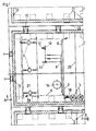
- the invention is explained in more detail by way of example in FIGS. 1 and 2.
- Fig. 1 shows a section of the ship without the outer hull, deck and upper tank insulation.
- Fig. 2 shows the section AB in Fig. 1.
- the completely insulated tank (1) is divided into two tank rooms by the wall (20) amidships.
- a transverse bulkhead (22) is located between the tanks (1).
- the tank is firmly connected to the hull by the supports (2).
- Slide bearings (3) support the tank (1) and give it lateral guidance. They consist of steel brackets connected to the hull, on which the pockwood blocks connected to the tank (1), which protrude from the insulation (16), can move.
- Hydraulic damping elements (15) with gas springs are arranged between the transverse bulkhead (22) and the unfixed end wall of the tanks (1).
- heat exchangers (4) are flanged, which have vertically arranged heat exchanger surfaces and extend far into the tanks (1). They are connected in parallel to the thermal oil circuit (21) by means of valves that can be operated both manually and optionally controlled via a temperature sensor (not shown). In this way, individual heat exchangers can be pulled without having to interrupt the thermal oil circuit. It is also possible to have two manually operated heat exchangers Shut-off devices and a temperature-controlled one to use.
- the tank bottom is inclined diagonally from an outer corner towards the center by about 3 to 5 °.
- the suction port of the submersible pump (5) is located at the lowest point, the preferably heated sump.
- the drive shaft and the pressure port are pulled out of the tank (1) and connected to the tank roof via a flange.
- the encapsulated thyristor controlled motor is located above the deck.
- the submersible pump (5) is inserted from above into a holder located in the tank (5) (not shown).
- the pressure port of the pump (5), the flushing line (6) and the product line (7) for filling and emptying are connected to each other via a three-way valve (18).
- the product is pumped through the rinsing line (6), which is provided with nozzles (19) directed into the corners.
- the tap (18) is changed over and the pressure nozzle is connected to the product line (7) and when filling the product line (7) to the flushing line (6).
- Pumps with reversible flow direction can also be filled via the pressure port.
- the flushing line (6) is fixed to the floor by means of fork-like holders. The filling and emptying process is controlled using a non-mechanical level indicator (13).
- the tanks (1) are also connected via a gas suspension line (8) to the respective inertized land tank, so that the inert gases - possibly loaded with aromatic vapors - are not blown off into the free atmosphere or by a flare must be burned off and the inert gas consumption can be kept as low as possible.
- the tank is connected to an inert gas line (9) if larger amounts of inert gas are required in the event of a sudden drop in pressure.
- the same or a different tank nozzle receives an overpressure (10) and a vacuum safety valve (11).
- the overpressure safety valve (10) is provided with a flame arrester (12).
- the vacuum safety valve (11) is connected to the inert gas line (9).
- each tank room is provided with at least one insulated manhole (14) through the deck. In order to ensure the necessary stability when empty, the ship is equipped with ballast tanks (17) between the two hulls.
- the ships are also to operate on inland waters, they must have a relatively shallow draft and must comply with the rules of inland navigation, which roughly correspond to the ADNR rules for shipping on the Rhine. In terms of equipment, the ships must comply with the safety regulations for K1 ships.
- All pipe systems including the gas pipes, are provided with trace heating, for example with thermal oil, and are well insulated.
- the tanks cannot be cleaned with water but only with solvents.
- good pitch solvents are like
- anthracene oil suitable for this purpose which are preferably heated to about 80 ° C.
- the tank to be cleaned is partially filled with the solvent, which is conveyed by means of the submersible pump (5) into one or more rotating washing guns that were suspended from the deck in the manholes.
- the solvent is circulated throughout the washing process.
- the contaminated solvent is then pumped into a separate tank, from where it can be pumped off for reprocessing.
- it makes sense to carry out the tank cleaning in the port where the solvent in the tank truck can be started up and the one contaminated with pitch residues can be removed directly for processing.
Landscapes
- Chemical & Material Sciences (AREA)
- Engineering & Computer Science (AREA)
- Combustion & Propulsion (AREA)
- Mechanical Engineering (AREA)
- Ocean & Marine Engineering (AREA)
- Filling Or Discharging Of Gas Storage Vessels (AREA)
Applications Claiming Priority (2)
| Application Number | Priority Date | Filing Date | Title |
|---|---|---|---|
| DE19863611920 DE3611920A1 (de) | 1986-04-09 | 1986-04-09 | Schiff fuer den fluessigtransport hochschmelzender aromatischer kohlenwasserstoffe |
| DE3611920 | 1986-04-09 |
Publications (3)
| Publication Number | Publication Date |
|---|---|
| EP0240664A2 true EP0240664A2 (fr) | 1987-10-14 |
| EP0240664A3 EP0240664A3 (en) | 1988-09-21 |
| EP0240664B1 EP0240664B1 (fr) | 1990-09-12 |
Family
ID=6298305
Family Applications (1)
| Application Number | Title | Priority Date | Filing Date |
|---|---|---|---|
| EP87101617A Expired - Lifetime EP0240664B1 (fr) | 1986-04-09 | 1987-02-06 | Bateau pour le transport d'hydrocarbures aromatiques fondant à haute température |
Country Status (9)
| Country | Link |
|---|---|
| US (1) | US4744321A (fr) |
| EP (1) | EP0240664B1 (fr) |
| JP (1) | JP2695159B2 (fr) |
| CA (1) | CA1283003C (fr) |
| DE (2) | DE3611920A1 (fr) |
| DK (1) | DK179487A (fr) |
| ES (1) | ES2017942B3 (fr) |
| NO (1) | NO871479L (fr) |
| PL (1) | PL154663B1 (fr) |
Cited By (2)
| Publication number | Priority date | Publication date | Assignee | Title |
|---|---|---|---|---|
| EP2681107A4 (fr) * | 2011-03-03 | 2016-06-29 | Ulmatec Pyro As | Procédé et système pour chauffer un fluide à l'intérieur de plusieurs réservoirs |
| CN106813259A (zh) * | 2017-03-22 | 2017-06-09 | 福建省环境工程有限公司 | 一种用于焦油处理的装置及方法 |
Families Citing this family (12)
| Publication number | Priority date | Publication date | Assignee | Title |
|---|---|---|---|---|
| DE4037577A1 (de) * | 1990-11-26 | 1992-05-27 | Paraskevopoulos George | Tankschiff |
| US5379711A (en) * | 1992-09-30 | 1995-01-10 | The United States Of America As Represented By The Secretary Of The Navy | Retrofittable monolithic box beam composite hull system |
| DE4414852C1 (de) * | 1994-04-28 | 1995-07-27 | Kaefer Isoliertechnik | Laderaum eines Kühlschiffes |
| AU2008226844A1 (en) * | 2007-03-13 | 2008-09-18 | Merck Sharp & Dohme Corp. | Inhibitors of janus kinases and/or 3-phosphoinositide-dependent protein kinase-1 |
| CN101668677B (zh) | 2007-04-26 | 2013-11-06 | 埃克森美孚上游研究公司 | 独立的皱褶液化天然气储罐 |
| US9045194B2 (en) | 2012-08-09 | 2015-06-02 | Martin Operating Partnership L.P. | Retrofitting a conventional containment vessel into a complete integral tank double-hull cargo containment vessel |
| US9302562B2 (en) | 2012-08-09 | 2016-04-05 | Martin Operating Partnership L.P. | Heating a hot cargo barge using recovered heat from another vessel using an umbilical |
| US20140041566A1 (en) * | 2012-08-09 | 2014-02-13 | Martin Operating Partnership LP | Complete integral tank double-hull cargo containment system vessel in maritime service |
| US20140318630A1 (en) * | 2013-04-24 | 2014-10-30 | Vopak North America, Inc. | Handling Bituminous Crude Oil in Tank Cars |
| CN103661911B (zh) * | 2013-11-29 | 2017-05-03 | 大连船舶重工集团有限公司 | 一种船舶燃油深舱加热系统 |
| KR101499902B1 (ko) * | 2014-06-10 | 2015-03-10 | 대우조선해양 주식회사 | 재기화장치를 갖는 해양구조물 및 상기 해양구조물에서 lng 저장탱크를 운용하는 방법 |
| CN105253265A (zh) * | 2015-10-21 | 2016-01-20 | 上海船舶研究设计院 | 一种用于沥青船的双侧壁式止浮装置 |
Family Cites Families (12)
| Publication number | Priority date | Publication date | Assignee | Title |
|---|---|---|---|---|
| US2738749A (en) * | 1955-01-17 | 1956-03-20 | Ingalls Shipbuilding Corp | Cargo vessel for transporting heated cargo and general cargo |
| US3147728A (en) * | 1959-06-20 | 1964-09-08 | Nippon Kokan Kk | Ship for the transportation of high temperature molten material |
| NL129933C (fr) * | 1960-03-22 | |||
| US3064612A (en) * | 1960-10-20 | 1962-11-20 | Maryland Shipbuilding And Dryd | Carrier constructions for bulk fluids |
| AT232439B (de) * | 1961-08-23 | 1964-03-25 | Becker Kg Westhydraulik | Vorrats- und Lagerbehälter mit indirekter Beheizung |
| US3425583A (en) * | 1966-09-07 | 1969-02-04 | Mcmullen John J | Arrangement for keying liquefied gas storage tanks within a transport vessel |
| NO121316B (fr) * | 1968-10-23 | 1971-02-08 | Patents & Developments A S | |
| US3767150A (en) * | 1970-05-22 | 1973-10-23 | J Tabata | Apparatus for mounting low temperature liquid storage tanks |
| US3833014A (en) * | 1972-11-15 | 1974-09-03 | Hy Way Heat Systems | Asphalt storage tank with inert gas seal |
| JPS5855956B2 (ja) * | 1978-12-26 | 1983-12-12 | 日本鋼管株式会社 | ケミカルタンカ− |
| GB2156285B (en) * | 1981-06-16 | 1986-05-08 | Hitachi Shipbuilding Eng Co | Ship for transporting coal slurry |
| JP5332957B2 (ja) | 2009-06-29 | 2013-11-06 | 新日鐵住金株式会社 | 抵抗溶接用冷延鋼板およびその製造方法 |
-
1986
- 1986-04-09 DE DE19863611920 patent/DE3611920A1/de not_active Withdrawn
-
1987
- 1987-02-06 DE DE8787101617T patent/DE3764840D1/de not_active Expired - Lifetime
- 1987-02-06 ES ES87101617T patent/ES2017942B3/es not_active Expired - Lifetime
- 1987-02-06 EP EP87101617A patent/EP0240664B1/fr not_active Expired - Lifetime
- 1987-03-23 US US07/028,933 patent/US4744321A/en not_active Expired - Lifetime
- 1987-04-07 CA CA000534029A patent/CA1283003C/fr not_active Expired - Lifetime
- 1987-04-07 PL PL1987265042A patent/PL154663B1/pl unknown
- 1987-04-08 DK DK179487A patent/DK179487A/da not_active Application Discontinuation
- 1987-04-08 NO NO871479A patent/NO871479L/no unknown
- 1987-04-09 JP JP62085909A patent/JP2695159B2/ja not_active Expired - Lifetime
Cited By (2)
| Publication number | Priority date | Publication date | Assignee | Title |
|---|---|---|---|---|
| EP2681107A4 (fr) * | 2011-03-03 | 2016-06-29 | Ulmatec Pyro As | Procédé et système pour chauffer un fluide à l'intérieur de plusieurs réservoirs |
| CN106813259A (zh) * | 2017-03-22 | 2017-06-09 | 福建省环境工程有限公司 | 一种用于焦油处理的装置及方法 |
Also Published As
| Publication number | Publication date |
|---|---|
| ES2017942B3 (es) | 1991-03-16 |
| PL154663B1 (en) | 1991-09-30 |
| JPS62244785A (ja) | 1987-10-26 |
| DE3611920A1 (de) | 1987-10-22 |
| NO871479D0 (no) | 1987-04-08 |
| US4744321A (en) | 1988-05-17 |
| DK179487A (da) | 1987-10-10 |
| JP2695159B2 (ja) | 1997-12-24 |
| EP0240664B1 (fr) | 1990-09-12 |
| CA1283003C (fr) | 1991-04-16 |
| PL265042A1 (en) | 1988-03-03 |
| NO871479L (no) | 1987-10-12 |
| DK179487D0 (da) | 1987-04-08 |
| EP0240664A3 (en) | 1988-09-21 |
| DE3764840D1 (de) | 1990-10-18 |
Similar Documents
| Publication | Publication Date | Title |
|---|---|---|
| EP0240664B1 (fr) | Bateau pour le transport d'hydrocarbures aromatiques fondant à haute température | |
| WO2013091772A1 (fr) | Structure flottante, en particulier navire porte-conteneurs | |
| US2048312A (en) | Ship for carrying fluids in bulk | |
| GB2041895A (en) | Fluid venting systems for tanker vessels | |
| DE1506270A1 (de) | Tankschiff fuer tiefsiedende Fluessiggase | |
| US5664514A (en) | Tanker provided with swash type bulkheads | |
| EP0049564B1 (fr) | Construction de pétrolier réduisant la perte de cargo liquide ayant un poids spécifique plus petit que celui de l'eau de mer | |
| US3240381A (en) | Surface cover for stored liquids | |
| DE2005800A1 (de) | Laderaumanordnung in Schiffen zum Transport giftiger Medien | |
| US3050951A (en) | Shipping container and method for transporting liquefied gases and the like | |
| US5203828A (en) | Guide and control means for diaphragm | |
| US5101750A (en) | Tanker ship hull for reducing cargo spillage | |
| US3339367A (en) | Method and apparatus for insulated submerged oil storage | |
| Shackleton et al. | Pollution of the Sea by Oil | |
| DE3323775A1 (de) | Vorrichtung zum wechselweisen transport bzw. lagerung verschiedenartiger fluessigkeiten | |
| DE1053342B (de) | Lade- und Entladeeinrichtung fuer ein Fahrzeug | |
| US5388541A (en) | Tanker ship design for reducing cargo spillage | |
| DE4007512C2 (fr) | ||
| Gallagher et al. | Floating-Roof Tanks: Design and Operation in the Petroleum Industry | |
| EP0611692A1 (fr) | Méthode pour le transport des cargaisons de pétrole par bateau et cuves pour la réalisation de la dite méthode | |
| CN119403993A (zh) | 用于生产、处理和精炼原料气的海上生产设施 | |
| DD207684A1 (de) | Schiff fuer schwerfluessige brennoele | |
| Neill et al. | Internal Corrosion in Floating Roof Gasoline Storage Tanks | |
| DE2636310A1 (de) | Vorrichtung zum transport von verfluessigten gasen | |
| KR820001051B1 (ko) | 액체 화물 탱크 구조 |
Legal Events
| Date | Code | Title | Description |
|---|---|---|---|
| PUAI | Public reference made under article 153(3) epc to a published international application that has entered the european phase |
Free format text: ORIGINAL CODE: 0009012 |
|
| AK | Designated contracting states |
Kind code of ref document: A2 Designated state(s): DE ES FR GB IT NL SE |
|
| PUAL | Search report despatched |
Free format text: ORIGINAL CODE: 0009013 |
|
| AK | Designated contracting states |
Kind code of ref document: A3 Designated state(s): DE ES FR GB IT NL SE |
|
| 17P | Request for examination filed |
Effective date: 19881019 |
|
| 17Q | First examination report despatched |
Effective date: 19890609 |
|
| ITF | It: translation for a ep patent filed | ||
| GRAA | (expected) grant |
Free format text: ORIGINAL CODE: 0009210 |
|
| AK | Designated contracting states |
Kind code of ref document: B1 Designated state(s): DE ES FR GB IT NL SE |
|
| GBT | Gb: translation of ep patent filed (gb section 77(6)(a)/1977) | ||
| REF | Corresponds to: |
Ref document number: 3764840 Country of ref document: DE Date of ref document: 19901018 |
|
| ET | Fr: translation filed | ||
| ITTA | It: last paid annual fee | ||
| PLBE | No opposition filed within time limit |
Free format text: ORIGINAL CODE: 0009261 |
|
| STAA | Information on the status of an ep patent application or granted ep patent |
Free format text: STATUS: NO OPPOSITION FILED WITHIN TIME LIMIT |
|
| 26N | No opposition filed | ||
| PGFP | Annual fee paid to national office [announced via postgrant information from national office to epo] |
Ref country code: ES Payment date: 19940228 Year of fee payment: 8 |
|
| REG | Reference to a national code |
Ref country code: FR Ref legal event code: TP |
|
| REG | Reference to a national code |
Ref country code: FR Ref legal event code: TP |
|
| REG | Reference to a national code |
Ref country code: GB Ref legal event code: 732E |
|
| EAL | Se: european patent in force in sweden |
Ref document number: 87101617.6 |
|
| NLS | Nl: assignments of ep-patents |
Owner name: RUETGERSWERKE AKTIENGESELLSCHAFT TE FRANKFORT A.D. |
|
| PG25 | Lapsed in a contracting state [announced via postgrant information from national office to epo] |
Ref country code: ES Free format text: LAPSE BECAUSE OF NON-PAYMENT OF DUE FEES Effective date: 19950207 |
|
| NLS | Nl: assignments of ep-patents |
Owner name: MICHAEL PFEUFFER TE KREFELD, BONDSREPUBLIEK DUITSL |
|
| REG | Reference to a national code |
Ref country code: ES Ref legal event code: FD2A Effective date: 19990301 |
|
| REG | Reference to a national code |
Ref country code: GB Ref legal event code: IF02 |
|
| PG25 | Lapsed in a contracting state [announced via postgrant information from national office to epo] |
Ref country code: IT Free format text: LAPSE BECAUSE OF NON-PAYMENT OF DUE FEES;WARNING: LAPSES OF ITALIAN PATENTS WITH EFFECTIVE DATE BEFORE 2007 MAY HAVE OCCURRED AT ANY TIME BEFORE 2007. THE CORRECT EFFECTIVE DATE MAY BE DIFFERENT FROM THE ONE RECORDED. Effective date: 20050206 |
|
| PGFP | Annual fee paid to national office [announced via postgrant information from national office to epo] |
Ref country code: GB Payment date: 20060201 Year of fee payment: 20 |
|
| PGFP | Annual fee paid to national office [announced via postgrant information from national office to epo] |
Ref country code: NL Payment date: 20060205 Year of fee payment: 20 |
|
| PGFP | Annual fee paid to national office [announced via postgrant information from national office to epo] |
Ref country code: SE Payment date: 20060207 Year of fee payment: 20 |
|
| PGFP | Annual fee paid to national office [announced via postgrant information from national office to epo] |
Ref country code: FR Payment date: 20060220 Year of fee payment: 20 |
|
| PGFP | Annual fee paid to national office [announced via postgrant information from national office to epo] |
Ref country code: DE Payment date: 20060413 Year of fee payment: 20 |
|
| PG25 | Lapsed in a contracting state [announced via postgrant information from national office to epo] |
Ref country code: GB Free format text: LAPSE BECAUSE OF EXPIRATION OF PROTECTION Effective date: 20070205 |
|
| PG25 | Lapsed in a contracting state [announced via postgrant information from national office to epo] |
Ref country code: NL Free format text: LAPSE BECAUSE OF EXPIRATION OF PROTECTION Effective date: 20070206 |
|
| REG | Reference to a national code |
Ref country code: GB Ref legal event code: PE20 |
|
| NLV7 | Nl: ceased due to reaching the maximum lifetime of a patent |
Effective date: 20070206 |
|
| EUG | Se: european patent has lapsed |