EP0237170B1 - Hitzebeständiger Stahl und daraus hergestellte Gasturbinenteile - Google Patents
Hitzebeständiger Stahl und daraus hergestellte Gasturbinenteile Download PDFInfo
- Publication number
- EP0237170B1 EP0237170B1 EP87300930A EP87300930A EP0237170B1 EP 0237170 B1 EP0237170 B1 EP 0237170B1 EP 87300930 A EP87300930 A EP 87300930A EP 87300930 A EP87300930 A EP 87300930A EP 0237170 B1 EP0237170 B1 EP 0237170B1
- Authority
- EP
- European Patent Office
- Prior art keywords
- turbine
- less
- compressor
- discs
- gas
- Prior art date
- Legal status (The legal status is an assumption and is not a legal conclusion. Google has not performed a legal analysis and makes no representation as to the accuracy of the status listed.)
- Expired - Lifetime
Links
Images


Classifications
-
- C—CHEMISTRY; METALLURGY
- C22—METALLURGY; FERROUS OR NON-FERROUS ALLOYS; TREATMENT OF ALLOYS OR NON-FERROUS METALS
- C22C—ALLOYS
- C22C38/00—Ferrous alloys, e.g. steel alloys
- C22C38/18—Ferrous alloys, e.g. steel alloys containing chromium
- C22C38/40—Ferrous alloys, e.g. steel alloys containing chromium with nickel
- C22C38/46—Ferrous alloys, e.g. steel alloys containing chromium with nickel with vanadium
-
- C—CHEMISTRY; METALLURGY
- C22—METALLURGY; FERROUS OR NON-FERROUS ALLOYS; TREATMENT OF ALLOYS OR NON-FERROUS METALS
- C22C—ALLOYS
- C22C38/00—Ferrous alloys, e.g. steel alloys
- C22C38/18—Ferrous alloys, e.g. steel alloys containing chromium
- C22C38/40—Ferrous alloys, e.g. steel alloys containing chromium with nickel
- C22C38/44—Ferrous alloys, e.g. steel alloys containing chromium with nickel with molybdenum or tungsten
-
- Y—GENERAL TAGGING OF NEW TECHNOLOGICAL DEVELOPMENTS; GENERAL TAGGING OF CROSS-SECTIONAL TECHNOLOGIES SPANNING OVER SEVERAL SECTIONS OF THE IPC; TECHNICAL SUBJECTS COVERED BY FORMER USPC CROSS-REFERENCE ART COLLECTIONS [XRACs] AND DIGESTS
- Y10—TECHNICAL SUBJECTS COVERED BY FORMER USPC
- Y10S—TECHNICAL SUBJECTS COVERED BY FORMER USPC CROSS-REFERENCE ART COLLECTIONS [XRACs] AND DIGESTS
- Y10S60/00—Power plants
- Y10S60/909—Reaction motor or component composed of specific material
Definitions
- the present invention relates generally to a heat resistant steel, and more particularly to gas turbine parts and a gas turbine in which the heat resistant steel is used.
- Cr-Mo-V steel is currently used in the discs for a gas turbine.
- martensitic steel well matches other constitutent parts and also has a sufficient high-temperature strength.
- Typical martensitic steels have been disclosed in JP-A-110661/83 and JP-A-138054/85, and JP-B-2739/71.
- these materials are not necessarily able to achieve a high creep rupture strength at temperatures between 400 and 450°C, and further since the toughness of these materials after having been heated at high temperatures for long period of time is low, they cannot be used for turbine discs, so that an improvement in the efficiency of gas turbines cannot be achieved.
- US-T-964003 (Defensive Publication) describes a martensitic steel consisting of 0.10-0.2% C, less than 0.90% Mn, less than 0.35% Si, 11.0-12.5% Cr, 2.0-3.0% Ni, 1.50-2.0% Mo, 0.25-0.40% V, 0.10-0.25% Nb, less than 0.05% N and balance Fe, for use in a turbine.
- Mn content is 0.68% and the Ni content is 2.50% (a ratio Mn/Ni of 0.272).
- JP-A-56-35754 describes alloy steels for use as turbine blades at very low temperature. In alloy no 6 the Mn/Ni ratio is 0.106 and the amount of Ni is 3.97% and the amount of Mn is 0.42%.
- this heat resistant steel contains 0.07 to 0.15 wt. % of C, 0.01 to 0.1 wt. % of Si, 0.15 to 0.4 wt. % of Mn, 11 to 12.5 wt. % of Cr, 2.2 to 3.0 wt. % of Ni, 1.8 to 2.5 wt. % of Mo, 0.04 to 0.08 wt. % in total of either or both of Nb and Ta, 0.15 to 0.25 wt. % of V, 0.04 to 0.08 wt. % of N, the ratio (Mn/Ni) of Mn to Ni being 0.04 to 0.10, and has a wholly tempered martensite structure.
- the steel has the properties set out in claim 3.
- composition of the steel of the present invention is preferably so adjusted that the Cr equivalent calculated from the following equation is less than 10, and it is also necessary or at least desirable to ensure that the steel contains materially no ⁇ -ferrite phase.
- Cr equivalent - 40C - 2Mn - 4Ni - 30N + 6Si + Cr + 4Mo + 11V + 5Nb + 2.5Ta (where the above equation is calculated using the contents in weight percent of the respective elements in the alloy.)
- the present invention also provides a gas turbine disc having in its outer circumferential portion a plurality of recessed grooves into which blades are embedded, having a maximum thickness in its center and having in its outer circumferential side a plurality of through-holes into which bolts are inserted to connect a plurality of the discs, the disc being made of a martensitic steel as described above.
- a plurality of turbine discs are connected together at their outer circumferential sides by the bolts with annular spacers interposed therebetween.
- Such a spacer may be made of a martensitic steel of the invention as described above.
- a ratio (t/D) of the thickness (t) in the central portion of the disc to the diameter (D) thereof is limited to 0.15 to 0.3, thereby enabling a reduction in the weight of the disc.
- a ratio (t/D) is limited to 0.18 to 0.22 it is possible to shorten the distance between the respective discs, so that improvement in the thermal efficiency can be expected.
- a minimum of 0.05 wt. % of C is needed in order to obtain a high tensile strength and a high proof stress.
- a metal structure becomes unstable when the steel is exposed to high temperatures for long period of time thereby decreasing a 105-h creep rupture strength, so that the C content must be less than 0.20 wt. %.
- the C content is 0.07 to 0.15 wt. %, and more preferably 0.10 to 0.14 wt. %.
- Si is added as deoxidizer and Mn as deoxidizer and desulfurizer when the steel is melted, and they are affective even with a small amount.
- Si is a ⁇ -ferrite former, and since the addition of a large amount of Si causes the formation of ⁇ -ferrite which decreases the fatigue strength and toughness, the Si content must be less than 0.5 wt. %.
- a carbon vacuum deoxidation method, an electroslag melting method and the like it is unnecessary to add Si, so that it is preferable to add no Si.
- the Si content is preferably less than 0.2 wt. % from the viewpoint of embrittlement and, even if no Si is added, 0.01 to 0.1 wt. % of Si is contained as an impurity.
- the Mn content must be less than 0.6 wt. %, since Mn promotes the embrittlement by heating.
- Mn is effective as a desulfurizer, and thus the Mn content is 0.1 to 0.4 wt. % so as not to cause any embrittlement by heating. Moreover, most preferably it is 0.1 to 0.25 wt. %.
- the total content of Si + Mn is preferably less than 0.3 wt. % from the viewpoint of the prevention of embrittlement.
- Cr enhances a corrosion resistance and a high-temperature strength but, if more than 13 wt. % of Cr is added, it causes the formation of ⁇ -ferrite structure. If the Cr content is less than 8 wt. % no sufficient corrosion resistance and high-temperature strength can be obtained. Therefore, the Cr content is limited to 8 to 13 wt. %. In particular, the Cr content is preferably 11 to 12.5 wt. %.
- Mo enhances a creep rupture strength owing to its solid solution strengthening and precipitation strengthening actions, and it further has the effect of preventing the embrittlement. If the Mo content is less than 1.5 wt. %, no sufficient effect of enhancing the creep rupture strength is obtained. More than 3.0 wt. % of Mo causes the formation of ⁇ -ferrite. Therefore, the Mo content is limited to 1.5 to 3.0 wt. %, preferably 1.8 to 2.5 wt. % in particular. Moreover, when the Ni content exceeds 2.1 wt. %, Mo has such an effect that the higher the Mo content is, the higher is the creep rupture strength, and in particular this effect is remarkable when the Mo content is higher than 2.0 wt. %.
- V and Nb precipitate carbide, thereby bring about an effect of enhancing the high-temperature strength as well as improving the toughness.
- the minimum amount of V in the invention is 0.05 % wt. If the contents of V and Nb are respectively less than 0.1 wt. % and less than 0.02 wt. %, no sufficient effect may be obtained, whereas if the contents of V and Nb are respectively higher than 0.3 wt. % and higher than 0.2 wt. %, it causes the formation of ⁇ -ferrite and exhibits a tendency to decrease the toughness.
- the V content is 0.15 to 0.25 wt. % and the Nb content is 0.04 to 0.08 wt. %.
- Ta may be added in exactly same content, and Nb and Ta may also be added in combination.
- Ni enhances toughness after having been heated at high temperatures for long period of time, and has an effect of preventing the formation of ⁇ -ferrite. If the Ni content is less than 2.0 wt. %, no sufficient effect can be obtained, whereas if it is higher than 3 wt. %, long-time creep rupture strength is decreased. In particular, it is preferable that the Ni content is 2.2 to 3.0 wt. %, more preferably it exceeds 2.5 wt. %.
- Ni has an effect of preventing the embrittlement by heating, whereas conversely Mn does harm this effect.
- the present inventors have found that there is a close correlation between these elements. Namely, they found the fact that when a ratio (Mn/Ni) is less than 0.11, the embrittlement by heating is remarkably prevented.
- the ratio is preferably less than 0.10, more preferably 0.04 to 0.10.
- N is effective in improving a creep rupture strength and preventing the formation of ⁇ -ferrite, but if the N content is less than 0.02 wt. %, no sufficient effect can be obtained. If the N content exceeds 0.1 wt. %, the toughness is decreased. In particular, the superior properties can be obtained in the N content range of 0.04 wt. % to 0.08 wt. %.
- Co is effective in strengthening the steel but promotes the embrittlement, so that the Co content should be less than 0.5 wt. %. Since W contributes to the strengthening similarly to Mo, it may be contained in an amount less than 1 wt. %.
- the high-temperature strength can be improved by adding less than 0.01 wt. % of B, less than 0.3 wt. % of Al, less than 0.5 wt. % of Ti, less than 0.1 wt. % of Zr, less than 0.1 wt. % of Hf, less than 0.01 wt. % of Ca, less than 0.01 wt. % of Mg, less than 0.01 wt. % of Y, less than 0.01 wt. % of rare earth elements and less than 0.5 wt. % of Cu.
- the material is uniformly heated at a temperature (at the lowest: 900°C, at the highest: 1150°C) sufficient to transform it to a complete austenite, and then quenched so as to obtain a martensite structure.
- the martensite structure is preferably obtained by quenching the material at a rate higher than 100°C/h, and it is heated to and held at a temperature between 450 and 600°C (a first tempering), and then it is subjected to a second tempering by being heated to and held at a temperature between 550 and 650°C.
- the quenching it is preferable to stop the quenching at a temperature higher than 150°C. It is preferable to carry out the hardening by an oil hardening or a water spray hardening.
- the first tempering is started from the temperature at which the quenching is stopped.
- More than one of the aforementioned distance piece, turbine spacer, turbine stacking bolt, compressor stacking bolt and at least a final stage disc of the compressor discs can be made of heat resistant steels of the present invention. By composing all of these parts with this heat resistant steel, it is possible to further raise the temperature of gas thereby improving the thermal efficiency. High resistance to embrittlement is obtained and a remarkably safe gas turbine is also obtained.
- a martensitic steel having a 450°C, 105-h creep rupture strength of higher than 40 kg/mm2 and a 20°C, V-notch Charpy impact value of higher than 5 kg - m/cm2 is preferably used as a material used for these parts, it has, particularly preferably, a 450°C, 105-h creep rupture strength of higher than 50 kg/mm2 and a 20°C, V-notch Charpy impact value of higher than 5 kg - m/cm2 after having been heated at 500°C for 103 hours.
- the compressor discs that for at least the final stage or those for all stages can be made of the aforementioned heat resistant steel; but since the temperature of gas is low in a zone from the first stage to the middle stage, another low alloy steel can be used for the discs in this zone, and the aforementioned heat resistant steel can be used for the discs in a zone from the middle stage to the final stage.
- a Ni-Cr-Mo-V steel containing 0.15 to 0.30 wt. % of C, less than 0.5 wt. % of Si, less than 0.6 wt. % of Mn, 1 to 2 wt.
- % of Cr 2.0 to 4.0 wt. % of Ni, 0.5 to 1 wt. % of Mo, 0.05 to 0.2 wt. % of V and the balance substantially Fe, and having a room temperature, tensile strength of higher than 80 kg/mm2 and a room temperature, V-notch Charpy impact value of higher than 20 kg - m/cm2, and for the discs from the middle stage to the following stages except for the final stage it is possible to use a Cr-Mo-V steel containing 0.2 to 0.4 wt. % of C, 0.1 to 0.5 wt. % of Si, 0.5 to 1.5 wt. % of Mn, 0.5 to 1.5 wt.
- % of Cr less than 0.5 wt. % of Ni, 1.0 to 2.0 wt. % of Mo, 0.1 to 0.3 wt. % of V and the balance substantially Fe, and having a room temperature, tensile strength of higher than 80 kg/mm2, an elongation of higher than 18% and a reduction of area of higher than 50%.
- the aforementioned Cr-Mo-V steel can be used for the compressor stub shaft and the turbine stub shaft.
- the compressor disc of the present invention is of a flat circular shape and has in its outer portion a plurality of holes into which stacking bolts are inserted, and it is preferable that a ratio (t/D) of the minimum thickness (t) of the compressor disc to the diameter (D) thereof is limited to 0.05 to 0.10.
- the distance piece of the present invention is of a cylindrical shape and is provided on its both ends with flanges which are respectively connected to the compressor disc and the turbine disc by bolts, and it is preferable that a ratio (t/D) of the minimum thickness (t) to the maximum inner diameter (D) is limited to 0.05 to 0.10.
- a ratio (l/D) of the spacing (l) between the respective turbine discs to the diameter (D) of the gas turbine disc is limited to 0.15 to 0.25.
- the first to twelfth stage discs can be made of the aforementioned Ni-Cr-Mo-V steel
- the thirteenth to sixteenth stage discs can be made of the aforementioned Cr-Mo-V steel
- the seventeenth stage disc can be made of the aforementioned martensitic steel.
- the first stage disc has a higher rigidity than the disc in the following stage and the final stage disc has a higher rigidity than the disc in the preceding stage. Also, these discs are formed to be gradually smaller in thickness from the first to final stages, thereby reducing the stress produced by high-speed rotation.
- Each of the blades of the compressor is preferably made of a martensitic steel containing 0.05 to 0.2 wt. % of C, less than 0.5 wt. % of Si, less than 1 wt. % of Mn, 10 to 13 wt. % of Cr and the balance Fe, or a martensitic steel further containing in addition to the above composition less than 0.5 wt. % of Mo and less than 0.5 wt. % of Ni.
- a Ni-based cast alloy containing 0.05 to 0.2 wt. % of C, less than 2 wt. % of Si, less than 2 wt. % of Mn, 17 to 27 wt. % of Cr, less than 5 wt. % of Co, 5 to 15 wt. % of Mo, 10 to 30 wt. % of Fe, less than 5 wt. % of W, less than 0.02 wt.
- % of B and the balance substantially Ni and at its portions corresponding to the remaining stages a Fe-based cast alloy containing 0.3 to 0.6 wt. % of C, less than 2 wt. % of Si, less than 2 wt. % of Mn, 20 to 27 wt. % of Cr, 20 to 30 wt. % of Ni, 0.1 to 0.5 wt. % of Nb, 0.1 to 0.5 wt. % of Ti and the balance substantially Fe.
- These alloys are formed into a ring-shaped structure constituted by a plurality of blocks.
- the portion corresponding to the first stage turbine nozzle may be made of a Cr-Ni steel containing less than 0.05 wt. % of C, less than 1 wt. % of Si, less than 2 wt. % of Mn, 16 to 22 wt. % of Cr, 8 to 15 wt. % of Ni and the balance substantially Fe, and the portions corresponding to the other turbine nozzles are made of a high C-high Ni system cast alloy.
- Each of the turbine blades may be made of a Ni-based cast alloy containing 0.07 to 0.25 wt. % of C, less than 1 wt. % of Si, less than 1 wt. % of Mn, 12 to 20 wt. % of Cr, 5 to 15 wt. % of Co, 1.0 to 5.0 wt. % of Mo, 1.0 to 5.0 wt. % of W, 0.005 to 0.03 wt. % of B, 2.0 to 7.0 wt. % of Ti, 3.0 to 7.0 wt. % of Al, at least one selected from the group consisting of less than 1.5 wt. % of Nb, 0.01 to 0.5 wt.
- the turbine nozzle may be made of a Co-based cast alloy containing 0.20 to 0.60 wt. % of C, less than 2 wt. % of Si, less than 2 wt. % of Mn, 25 to 35 wt. % of Cr, 5 to 15 wt. % of Ni, 3 to 10 wt. % of W, 0.003 to 0.03 wt.
- % of B and the balance substantially Co having a structure in which eutectic carbide and secondary carbide are contained in an austenite phase matrix
- a Co-based cast alloy further containing in addition to the above composition at least one of 0.1 to 0.3 wt. % of Ti, 0.1 to 0.5 wt. % of Nb and 0.1 to 0.3 wt. % of Zr, and having a structure in which eutectic carbide and secondary carbide are contained in an austenite phase matrix.
- Both of these alloys are subjected to an aging treatment subsequently to a solution heat treatment so as to form the aforementioned precipitates, thereby strengthening the alloys.
- the diffusion coating of Al, Cr or Al + Cr may be applied onto the turbine blades. It is preferable that the thickness of the coating layer is 30 to 150 ⁇ m and that the coating is applied to the blades which are exposed to the gases.
- a plurality of combustors may be disposed around the turbine, and each of combustors may have a dual structure constituted by outer and inner cylinders.
- the inner cylinder may be made of a solution heat-treated Ni-based alloy containing 0.05 to 0.2 wt. % of C, less than 2 wt. % of Si, less than 2 wt. % of Mn, 20 to 25 wt. % of Cr, 0.5 to 5 wt. % of Co, 5 to 15 wt. % of Mo, 10 to 30 wt. % of Fe, less than 5 wt % of W, less than 0.02 wt. % of B and the balance substantially Ni, and having a wholly austenite structure.
- the inner cylinder is constituted by welding the above Ni-based alloy plate having been subjected to a plastic working to have a thickness of 2 to 5 mm, and provided over whole periphery of the cylindrical body with crescent louver holes through which air is supplied.
- Samples respectively having the compositions (weight percent) shown in Table 1 were melted in an amount of 20 kg, cast into ingots and heated to and forged at 1150°C, and thus the experimental materials were obtained. After these materials had been heated at 1150°C for 2 hours, they were subjected to air blast cooling and the cooling was stopped when the temperature reached 150°C, and they were subjected to a first tempering by being heated from this temperature to and held at 580°C for 2 hours followed by air cooling and then to a second tempering by being heated to and held at 605°C for 5 hours followed by furnace cooling.
- Test pieces for a creep rupture test, a tensile test and a V-notch Charpy impact test were extracted from the materials having been subjected to the heat treatments, and were supplied to the experiments.
- the impact test was effected on an embrittled material which had been obtained by heating the as heat-treated material at 500°C for 1000 hours. It is deemed from Larson-Miller parameters that this embrittled material has same conditions as the material embrittled by being heated at 450°C for 105 hours.
- samples Nos. 1 and 8 are materials according to the present invention, and samples Nos. 2 to 7 are comparative materials and sample No. 2 corresponds to M 152 steel which is currently used as a material for discs.
- Table 2 shows the mechanical properties of these samples. It has been confirmed that the materials of the present invention (samples Nos. 1 and 8) satisfactorily meet the 450°C, 105-h creep rupture strength (>50 kg/mm2) required as a material used for high-temperature and high-pressure gas turbines and the 25°C, V-notch Charpy impact value [higher than 4 kg - m (5 kg - m/cm2)] after the embrittlement treatment. In contrast, the material corresponding to M 152 (sample No.
- the respective samples satisfy the value of a creep rupture strength which is required as a material used for high-temperature and high-pressure gas turbines, but they cannot satisfy a V-notch Charpy impact value after the embrittlement since their value is lower than 3.5 kg-m.
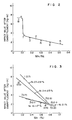
- Fig. 2 is a chart showing the relationship between the impact value after embrittlement and the ratio (Mn/Ni). As shown in Fig. 2, no remarkable improvement appears when the ratio (Mn/Ni) is higher than 0.12, but when the ratio is less than 0.11 the embrittlement is greatly improved to higher than 4 kg - m (5 kg - m/cm2), and further when the ratio is less than 0.10 it is improved to higher than 6 kg - m (7.5 kg - m/cm2). Mn is indispensable as deoxidizer and desulfurizer, so it is necessary to add Mn in an amount of less than 0.6 wt. %.
- Fig. 3 is a chart similar to Fig. 2, but showing the relationship between the impact value after embrittlement and the Mn content.
- Fig. 3 when the Ni content is less than 2.1 wt. % a reduction in the Mn content produces no large effect, but when the Ni content exceeds 2.1 wt. % a reduction in Mn content produces remarkable effect. In particular, when the Ni content is higher than 2.4 wt. % a large effect can be obtained.
- Fig. 4 is a chart similar to Fig. 2, but showing the relationship between the impact value after embrittlement and the Ni content.
- the Mn content is higher than 0.7 wt. % an increase in the Ni content improves the embrittlement to a slight extent, but it is clear that when the Mn content is less than 0.7 wt. % an increase in the Ni content remarkably improves the embrittlement.
- the Mn content is 0.15 to 0.4 wt. %
- the embrittlement is remarkably improved: namely, if it is higher than 2.4 wt. % impact values higher than 6 kg - m (7.5 kg - m/cm2) can be obtained, and further if it is higher than 2.5 wt. % those higher than 7 kg - m can be obtained.
- Fig. 5 is a chart showing the relationship between the 450°C x 105-h rupture strength and the Ni content.
- the Ni content of up to about 2.5 wt. % does not substantially influence the creep rupture strength, but when it exceeds 3.0 wt. % the strength is lowered to less than 50 kg/mm2, so that no desired strength level can be obtained.
- the lower the Mn content is the higher strength can be obtained, and that in the vicinity of 0.15 to 0.25 wt. % the most remarkable strengthening is obtained and thus a high strength is provided.
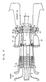
- Fig. 6 is a cross-sectional view schematically showing a gas turbine disc in accordance with the present invention.
- Table 3 shows the chemical composition (in percent by weight) of the gas turbine disc.
- Table 3 No. C Si Mn Cr Ni Mo Nb V N Mn/Ni Fe 9 0.12 0.04 0.20 11.1 2.70 2.05 0.07 0.20 0.05 0.07 Bal.
- the melting of the steel material was effected by the carbon vacuum deoxidation method. After forging had been completed, the forged steel was heated at 1050°C for two hours and hardened in oil of 150°C, and subsequently the hardened steel was subjected to the first tempering by being heated from 150°C to and held at 520°C for 5 hours followed by air cooling and then to the second tempering by being heated at 590°C for 5 hours followed by furnace cooling. After completion of these heat treatments, the steel material was machined into the shape shown in Fig. 6, and the disc thus obtained has an outer diameter of 1000 mm and a thickness of 200 mm. A center hole 11 is 65 mm in diameter. Holes into which the stacking bolts are inserted are formed in portions indicated by 12, and the turbine blades are embedded in portions indicated by 13.
- This disc had the superior properties, i.e., 8.0 kg-m (10 kg-m/cm2) in the impact value after the aforementioned embrittlement and 55.2 kg/mm2 in the 450°C x 105-h creep rupture strength.
- Fig. 1 is a cross-sectional view of the rotary section of a gas turbine showing an embodiment of the present invention, in which the above-mentioned discs are used.
- the rotary section shown comprises a turbine stub shaft 1, turbine blades 2, turbine stacking bolts 3, a turbine spacer 4, a distance piece 5, compressor discs 6, compressor blades 7, compressor stacking bolts 8, a compressor stub shaft 9, turbine discs 10 and a central hole 11.
- the gas turbine of the present invention has seventeen stages of the compressor discs 6 and two stages of the turbine blades 2.
- the turbine blades 2 may be three stages, and the steel of the present invention can be applied to both constructions.
- Table 4 The materials shown in Table 4 was made into a large piece of steel equivalent to a real size by the electroslag remelting method, followed by forging and heat treatment.
- the forging was effected in the temperature range of 850 to 1150°C, and the heat treatment was carried out under the conditions shown in Table 4.
- Table 4 shows the chemical compositions of the samples in percent by weight.
- the samples Nos. 6 to 9 had wholly tempered matensite structure
- the samples Nos. 10 and 11 had wholly tempered bainite structure.
- the sample No. 6 was used for the distance piece and the compressor disc at the final stage, the former having a thickness of 60 mm, a width of 500 mm and a length of 1000 mm, and the latter having a diameter of 1000 mm and a thickness of 180 mm.
- the sample No. 7 was used for the turbine discs each having a diameter of 1000 mm and a thickness of 180 mm.
- the sample No. 8 was used for the spacer having an outer diameter of 1000 mm, an inner diameter of 400 mm and a thickness of 100 mm.
- the sample No. 9 was used for both of the turbine and compressor stacking bolts each having a diameter of 40 mm and a length of 500 mm. Incidentally, the sample No. 9 was used also to produce bolts for connecting the distance piece and the compressor discs.
- the samples Nos. 10 and 11 were respectively forged into the turbine stub shaft and the compressor stub shaft each having a shape of 250 mm in diameter and 300 mm in length. Moreover, the steel sample No. 10 was used for the compressor discs 6 at the thirteenth to sixteenth stages, and the steel sample No. 11 was used for the compressor discs 6 at the first to twelfth stages. All the compressor discs 6 were produced so that the turbine and compressor discs had the same size.
- the test pieces were extracted, except for the steel No. 9, from the central portion of the samples in a direction perpendicular to the axial (longitudinal) direction of each of the samples. In this example, the test pieces were extracted in the longitudinal direction of the samples.
- Table 5 shows the results of tensile strength test at room temperature, V-notch Charpy impact test at 20°C and creep rupture test for the steel samples shown in Table 4.
- the 450°C x 105-h creep rupture strength was obtained from Larson-Miller method used in general.
- the steels (12Cr steel) Nos. 6 to 9 have a sufficient strength as a material used for a high-temperature gas turbine.
- the low alloy steels Nos. 10 and 11 for the stub shaft exhibited a low level of the 450°C creep rupture strength, but had a tensile strength of higher than 86 kg/mm2 and 20°C, V-notch Charpy impact value of higher than 7 kg - m/cm2. It has therefore been confirmed that the steels Nos. 10 and 11 sufficiently meet a strength necessary for a stub shaft (the tensile strength ⁇ 81 kg/mm2 and the 20°C, V-notch Charpy impact value ⁇ 5 kg - m/cm2).
- the gas turbine thus constituted by a combination of the aforementioned materials enables a compression ratio of 14.7, an allowable temperature of higher than 350°C, a compression efficiency of higher than 86% and a gas temperature of about 1200°C in the inlet of the nozzle at the first stage, thereby bringing about a thermal efficiency of higher than 32% (LHV).
- the temperature of the distance piece and the compressor disc at the final stage becomes 450°C at the highest. It is preferable that the former has a thickness of 25 to 30 mm and that the latter has a thickness of 40 to 70 mm.
- the turbine and compressor discs respectively have central through-hole, and a compressive residual stress remains along the central through-hole of the respective turbine discs.
- the aforesaid heat resistant steel of the invention shown in Table 3 was used for the turbine spacer 4, the distance piece 5 and the final-stage compressor disc 6, and the other constituent parts were likewise formed by using the same steel as described above.
- the resultant constitution enables a compression ratio of 14.7, an allowable temperature of higher than 350°C, a compression efficiency of higher than 86% and a gas temperature of 1200°C at the inlet of the nozzle at the first stage. In consequence, it is possible to obtain not only a thermal efficiency of higher than 32% but also, as described above, a high level of creep rupture strength and high impact value after the emtrittlement by heating, thereby obtaining a highly reliable gas turbine.
- Fig. 7 is an illustration of another preferred embodiment which has gas turbine discs made of the heat resistant steel of the present invention, and in particular shows the rotary section of the gas turbine partially in cross-section.
- two stages of turbine disc 10 are provided, and the turbine disc 10 on the upstream side of the gas flow has the central hole 11. All the turbine discs in this embodiment were made of the heat resistant steel shown in Table 3.
- the heat resistant steel shown in Table 3 was used for the compressor disc 6 at the final stage on the downstream side of the gas flow, the distance piece 5, the turbine spacer 4, the turbine stacking bolts 3 and the compressor stacking bolts 8.
- the alloys shown in Table 6 were used for other parts, i.e., the turbine blades 2, the turbine nozzle 14, the liners 17 of the combustors 15, the compressor blades 7, the compressor nozzle 16, the diaphragm 18 and the shroud 19.
- the turbine nozzle 14 and the turbine blades 2 were made by casting.
- the compressor in this embodiment has seventeen stages of compressor discs, and is arranged in the same manner as in Example 2.
- the turbine stub shaft 1 and the compressor stub shaft 9 in this embodiment were also constructed in the same manner as in Example 2.
- the turbine blade, turbine nozzle, shroud segment (1) and diaphragm listed in Table 6 were used at the first stage on the upstream side of the gas flow within the gas turbine, and the shroud segment (2) was used at the second stage.
- the final stage compressor disc 6 has a ratio (t/D) of minimum thickness (t) to outer diameter (D) of 0.08
- the distance piece 5 has a ratio (t/D) of 0.04.
- a ratio (t/D) of the maximum thickness (t) of the central portion of each of the turbine discs to the diameter (D) thereof is 0.19 in the first stage and 0.205 in the second stage
- a ratio (l/D) of the spacing (l) between the discs to the diameter (D) thereof is 0.21. Spacings are provided between the respective turbine discs.
- the respective turbine discs has a plurality of holes around the entire periphery thereof at equal intervals for inserting the bolts in order to connect the discs.
- the above-described arrangement enables a compression ratio of 14.7, an allowable temperature of higher than 350°C, a compression efficiency of higher than 86% and a gas temperature of 1200°C at the inlet of the nozzle disposed at the first stage of the turbine, thereby providing a thermal efficiency of higher than 32%.
- the aforementioned heat resistant steel which has a high creep rupture strength and is less embrittled by heating can be used for the turbine discs, the distance piece, the spacers, the compressor disc in the final stage and the stacking bolts.
- the alloy having a high high-temperature strength is used for the respective turbine blades
- the alloy having a high high-temperature strength and a high high-temperature ductility is used for the turbine nozzle and the alloy having a high high-temperature strength and a high fatigue resistance is used for the liners of the combustors, it is possible to obtain a well-balanced and totally reliable gas turbine.
- the heat resistant steel which provides the creep rupture strength and the impact value after embrittlement by heating required by disc for a high-temperature and high-pressure gas turbine (in the class of gas temperature: higher than 1200°C, compression ratio: 15), so that the gas turbine made by using the above steel can bring about excellent effects such as the attainment of an extremely high thermal efficiency.
Claims (31)
- Hitzebeständiger Stahl aus
0,05 bis 0,2 Gew.-% C,
unter 0,5 Gew.-% Si,
0,1 bis 0,40 Gew.-% Mn,
8 bis 13 Gew.-% Cr,
1,5 bis 3 Gew.-% Mo,
2 bis 3 Gew.-% Ni,
0,05 bis 0,3 Gew.-% V,
0,02 bis 0,2 Gew.-% insgesamt an Nb und/oder Ta,
0,02 bis 0,1 Gew.-% N,
unter 0,5 Gew.-% Co,
unter 1 Gew.-% W,
unter 0,01 Gew.-% B,
unter 0,3 Gew.-% Al,
unter 0,5 Gew.-% Ti,
unter 0,1 Gew.-% Zr,
unter 0,1 Gew.-% Hf,
unter 0,01 Gew.-% Ca,
unter 0,01 Gew.-% Mg,
unter 0,01 Gew.-% Y,
unter 0,01 Gew.-% Seltenerdelemente,
unter 0,5 Gew.-% Cu,
bei einem Verhältnis (Mn/Ni) von Mn zu Ni unter 0,11,
und mit Fe und unvermeidlichen Verunreinigungen als Rest. - Hitzebeständiger Stahl nach Anspruch 1, mit
0,07 bis 0,15 Gew.-% C,
0,01 bis 0,1 Gew.-% Si,
0,15 bis 0,4 Gew.-% Mn,
11 bis 12,5 Gew.-% Cr,
2,2 bis 3,0 Gew.-% Ni,
1,8 bis 2,5 Gew.-% Mo,
0,04 bis 0,08 Gew.-% insgesamt an Nb und/oder Ta,
0,15 bis 0,25 Gew.-% V,
0,04 bis 0,08 Gew.-% N,
wobei das Verhältnis (Mn/Ni) von Mn zu Ni 0,04 bis 0,10 ist,
und mit einer ganz durchgetemperten Martensitstruktur. - Hitzebeständiger Stahl nach Anspruch 1 oder Anspruch 2, mit einer Zeitstandfestigkeit bei 450°C, 10⁵ h über 50 kg/mm² und einem Charpy-Spitzkerbversuchswert bei 25°C über 5 kgm/cm² nach einer Erwärmung auf 500°C für 10³ Stunden.
- Gasturbinenscheibe, die an ihrem Außenumfangsbereich mehrere eingezogene Nuten aufweist, in die Blätter eingesetzt sind, mit maximaler Dicke in ihrer Mitte und mit mehreren Durchgangslöchern in ihrem Außenumfangsbereich, in die Schrauben eingesetzt sind, um mehrere der Scheiben miteinander zu verbinden, wobei die Scheibe aus einem Martensitstahl gemäß einem der Ansprüche 1 bis 3 besteht.
- Gasturbinenscheibe nach Anspruch 4, bei der das Verhältnis (t/D) der Dicke (t) der Scheibe zum Durchmesser (D) derselben im Bereich von 0,15 bis 0,30 liegt.
- Turbinenabstandshalter für eine Gasturbine zur Verwendung, wenn mehrere Turbinenscheiben an ihren Außenumfangsbereichen durch Schrauben miteinander unter Zwischenfügung des Abstandshalters oder von Abstandshaltern verbunden werden, wobei der Abstandshalter aus einem Martensitstahl gemäß einem der Ansprüche 1 bis 3 besteht.
- Zylindrisches Distanzstück für eine Gasturbine, wie es verwendet wird, wenn mehrere Turbinenscheiben und mehrere Kompressorscheiben miteinander über Schrauben durch die Abstandsstücke verbunden werden, wobei das Abstandsstück aus einem Martensitstahl gemäß einem der Ansprüche 1 bis 3 besteht.
- Zylindrisches Distanzstück gemäß Anspruch 7, bei dem das Verhältnis (t/D) der minimalen Dicke (t) des Distanzstücks zum maximalen Innendurchmesser (D) desselben im Bereich von 0,05 bis 0,10 liegt.
- Kompressorscheibe, die in ihrem Außenumfangsbereich mehrere eingezogene Nuten aufweist, in die Blätter eingesetzt sind und die in ihrem Außenumfangsbereich mehrere Durchgangslöcher aufweist, in die Schrauben eingesetzt sind, um mehrere Scheiben zu verbinden, und die in ihrer Mitte und in den mit den Durchgangslöchern versehenen Bereichen maximale Dicke aufweist, welche Kompressorscheibe aus einem Stahl gemäß einem der Ansprüche 1 bis 3 besteht.
- Kompressorscheibe nach Anspruch 9, bei der das Verhältnis (t/D) der Dicke (t) der Kompressorscheibe zum Durchmesser (D) derselben im Bereich von 0,05 bis 0,10 liegt.
- Stapelschrauben für eine Gasturbine, die jeweils dazu verwendet werden, mehrere Turbinenscheiben und Kompressorscheiben miteinander zu verbinden, und die aus einem Martensitstahl gemäß einem der Ansprüche 1 bis 3 hergestellt ist.
- Gasturbine mit:- einer Gasturbinenflanschwelle;- mehreren Turbinenscheiben, die durch Turbinenstapelschrauben über einen zwischengefügten Turbinenabstandshalter oder mehrere zwischengefügte Turbinenabstandshalter mit der Turbinenflanschwelle verbunden sind;- Turbinenblättern, die in jede der Turbinenscheiben eingesetzt sind;- einem mit den Turbinenscheiben über die Turbinenstapelschrauben verbundenen Distanzstück;- mehreren Kompressorscheiben, die mit dem Distanzstück über Kompressorstapelschrauben verbunden sind;- Kompressorblättern, die in jede der Kompressorscheiben eingesetzt sind; und- einer Kompressorflanschwelle, die integral mit der Erststufenscheibe der Kompressorscheiben ausgebildet ist;- wobei mindestens die Turbinenscheiben jeweils aus einem Martensitstahl gemäß einem der Ansprüche 1 bis 3 bestehen.
- Gasturbine nach Anspruch 12, bei der das Verhältnis (l/D) des Spalts (l) zwischen den jeweiligen Turbinenscheiben und dem Außendurchmesser (D) derselben 0,15 zu 0,25 beträgt.
- Gasturbine nach Anspruch 12 oder Anspruch 13, bei der die Endstufenscheibe der Kompressorscheiben stabiler ist als die Scheibe in der vorangehenden Stufe.
- Gasturbine nach einem der Ansprüche 12 bis 14, bei der mindestens ein Teil unter den Turbinenstapelschrauben, dem Distanzstück, dem Turbinenabstandshalter, mindestens den Kompressorscheiben von der Endstufe bis zur mittleren Stufe und der Kompressorstapelschrauben aus einem Martensitstahl besteht.
- Gasturbine nach einem der Ansprüche 12 bis 14, bei der mindestens eines der Teile der Turbinenstapelschrauben, des Distanzstücks, des Turbinenabstandshalters, mindestens der Kompressorscheiben von der Endstufe zur mittleren Stufe und der Kompressorstapelschrauben aus einem Martensitstahl besteht, der ein Stahl gemäß einem der Ansprüche 1 bis 3 ist.
- Gasturbine nach einem der Ansprüche 12 bis 16, bei der die Turbinenflanschwelle aus einem Cr-Mo-V-Stahl besteht, der aus folgendem besteht:
0,2 bis 0,4 Gew.-% C,
0,5 bis 1,5 Gew.-% Mn,
0,1 bis 0,5 Gew.-% Si,
0,5 bis 1,5 Gew.-% Cr,
unter 0,5 Gew.-% Ni,
1,0 bis 2,0 Gew.-% Mo,
0,1 bis 0,3 Gew.-% V und
Fe und unvermeidliche Verunreinigungen als Rest. - Gasturbine nach einem der Ansprüche 12 bis 17, bei der der Turbinenabstandshalter aus einem hitzebeständigen Stahl besteht, der aus folgendem besteht:
0,05 bis 0,2 Gew.-% C,
unter 0,5 Gew.-% Si,
unter 1 Gew.-% Mn,
8 bis 13 Gew.-% Cr,
1,5 bis 3,0 Gew.-% Mo,
unter 3 Gew.-% Ni,
0,05 bis 0,3 Gew.-% V,
0,02 bis 0,2 Gew.-% Nb,
0,02 bis 0,1 Gew.-% N und
Fe und unvermeidliche Verunreinigungen als Rest. - Gasturbine nach einem der Ansprüche 12 bis 18, bei der die Turbinenstapelschrauben jeweils aus einem hitzebeständigen Stahl bestehen, der aus folgendem besteht:
0,05 bis 0,2 Gew.-% C,
unter 0,5 Gew.-% Si,
unter 1 Gew.-% Mn,
8 bis 13 Gew.-% Cr,
1,5 bis 3,0 Gew.-% Mo,
unter 3 Gew.-% Ni,
0,05 bis 0,3 Gew.-% V,
0,02 bis 0,2 Gew.-% Nb,
0,02 bis 0,1 Gew.-% N und
Fe und unvermeidliche Verunreinigungen als Rest. - Garturbine nach einem der Ansprüche 12 bis 19, bei der das Turbinendistanzstück aus einem hitzebeständigen Stahl besteht, der aus folgendem besteht:
0,05 bis 0,2 Gew.-% C,
unter 0,5 Gew.-% Si,
unter 1 Gew.-% Mn,
8 bis 13 Gew.-% Cr,
1,5 bis 3,0 Gew.-% Mo,
unter 3 Gew.-% Ni,
0,05 bis 0,3 Gew.-% V,
0,02 bis 0,2 Gew.-% Nb,
0,02 bis 0,1 Gew.-% N und
Fe und unvermeidliche Verunreinigungen als Rest. - Gasturbine nach einem der Ansprüche 12 bis 20, bei der die Kompressorstapelschrauben jeweils aus einem hitzebeständigen Stahl bestehen, der aus folgendem besteht:
0,05 bis 0,2 Gew.-% C,
unter 0,5 Gew.-% Si,
unter 1 Gew.-% Mn,
8 bis 13 Gew.-% Cr,
1,5 bis 3,0 Gew.-% Mo,
unter 3 Gew.-% Ni,
0,05 bis 0,3 Gew.-% V,
0,02 bis 0,2 Gew.-% Nb,
0,02 bis 0,1 Gew.-% N und
Fe und unvermeidliche Verunreinigungen als Rest. - Gasturbine nach einem der Ansprüche 12 bis 21, bei der die Kompressorblätter jeweils aus einem Martensitstahl bestehen, der aus folgendem besteht:
0,05 bis 0,2 Gew.-% C,
unter 0,5 Gew.-% Si,
unter 1 Gew.-% Mn,
10 bis 13 Gew.-% Cr und
Fe und unvermeidliche Verunreinigungen als Rest. - Gasturbine nach einem der Ansprüche 12 bis 22, bei der die von der ersten bis in die mittlere Stufe auf der stromaufwärtigen Seite einer Gasströmung angeordneten Kompressorscheiben jeweils aus einem Ni-Cr-Mo-V-Stahl bestehen, der aus folgendem besteht:
0,15 bis 0,30 Gew.-% C,
unter 0,5 Gew.-% Si,
unter 0,6 Gew.-% Mn,
1 bis 2 Gew.-% Cr,
2,0 bis 4,0 Gew.-% Ni,
0,5 bis 1,0 Gew.-% Mo,
0,05 bis 0,2 Gew.-% V und
Fe und unvermeidliche Verunreinigungen als Rest,
und wobei die von der mittleren Stufe ausgehend bis zur stromabwärtigen Seite hin angeordneten Kompressorscheiben mit Ausnahme derjenigen in der Endstufe jeweils aus einem Cr-Mo-V-Stahl bestehen, der aus folgendem besteht:
0,2 bis 0,4 Gew.-% C,
0,1 bis 0,5 Gew.-% Si,
0,5 bis 1,5 Gew.-% Mn,
0,5 bis 1,5 Gew.-% Cr,
unter 0,5 Gew.-% Ni,
1,2 bis 2,0 Gew.-% Mo,
0,1 bis 0,3 Gew.-% V und
im wesentlichen Fe und unvermeidliche Verunreinigungen als Rest. - Gasturbine nach einem der Ansprüche 12 bis 23, bei der die Kompressorflanschwelle aus einem Cr-Mo-V-Stahl besteht, der aus folgendem besteht:
0,15 bis 0,3 Gew.-% C,
unter 0,6 Gew.-% Mn,
unter 0,5 Gew.-% Si,
2,0 bis 4,0 Gew.-% Ni,
1 bis 2 Gew.-% Cr,
0,5 bis 1 Gew.-% Mo,
0,05 bis 0,2 Gew.-% V und
Fe und unvermeidliche Verunreinigungen als Rest. - Gasturbine nach Anspruch 12 oder Anspruch 13, bei der der Stahl der Turbinenscheiben eine ganz durchgetemperte Martensitstruktur aufweist.
- Gasturbine nach einem der Ansprüche 12 bis 15, bei der das Turbinendistanzstück und mindestens die als Endstufenscheibe verwendete Kompressorscheibe auf der Hochtemperaturseite jeweils aus einem Martensitstahl gemäß einem der Ansprüche 1 bis 3 bestehen.
- Gasturbine nach einem der Ansprüche 12 bis 15, bei der die Turbinenstapelschrauben, die Abstandshalter, die Turbinenscheiben, das Distanzstück, die Kompressorstapelschrauben und die als Endstufenscheibe verwendete Kompressorscheibe auf der Hochtemperaturseite jeweils aus einem Martensitstahl bestehen, der eine Zeitstandfestigkeit bei 450°C, 10⁵ h über 50 kg/mm² und einen Charpy-Spitzkerbversuchswert bei 25°C über 5 kgm/cm² nach Erhitzen auf 500°C für 10³ Stunden aufweist und eine ganz durchgetemperte Martensitstruktur aufweist.
- Gasturbine nach einem der Ansprüche 12 bis 27 mit:- der genannten Gasturbinenflanschwelle;- den genannten mehreren Turbinenscheiben, die durch Turbinenstapelschrauben über einen zwischengefügten Turbinenabstandshalter oder mehrere zwischengefügte Turbinenabstandshalter mit der Turbinenflanschwelle verbunden sind;- den Turbinenblättern, die in jede der Turbinenscheiben eingesetzt sind;- einem Deckband, das ringförmig so angeordnet ist, daß es in Gleitberührung mit den Außenumfangsenden der Turbinenblätter steht;- mehreren Brennkammern mit jeweils einer Turbinendüse zum Richten einer Strömung des Hochtemperaturgases gegen die Turbinenblätter, um ein Drehen derselben zu bewirken, und mit einem zylindrischen Körper zum Erzeugen des Hochtemperaturgases;- dem genannten, mit den Turbinenscheiben über die Turbinenstapelschrauben verbundenen Distanzstück;- den genannten mehreren Kompressorscheiben, die mit dem Distanzstück über Kompressorstapelschrauben verbunden sind;- den genannten Kompressorblättern, die in jede der Kompressorscheiben eingesetzt sind; und- der genannten Kompressorflanschwelle, die integral mit der Erststufenscheibe der Kompressorscheiben ausgebildet ist;- wobei das Deckband in seinem dem Turbinenblatt der ersten Stufe entsprechenden Bereich aus einer Legierung auf Ni-Grundlage besteht, die aus folgendem besteht:
0,05 bis 0,2 Gew.-% C,
unter 2 Gew.-% Si,
unter 2 Gew.-% Mn,
17 bis 27 Gew.-% Cr,
unter 5 Gew.-% Co,
5 bis 15 Gew.-% Mo,
10 bis 30 Gew.-% Fe,
unter 5 Gew.-% W,
unter 0,02 Gew.-% B und
Ni und unvermeidliche Verunreinigungen als Rest, mit durchgehend Austenitstruktur, und
es in seinen Bereichen, die den in den restlichen Stufen angeordneten Turbinenblättern entsprechen, aus einer Gußlegierung auf Fe-Grundlage besteht, die aus folgendem besteht:
0,3 bis 0,6 Gew.-% C,
unter 2 Gew.-% Si,
unter 2 Gew.-% Mn,
20 bis 27 Gew.-% Cr,
20 bis 30 Gew.-% Ni,
0,1 bis 0,5 Gew.-% Nb,
0,1 bis 0,5 Gew.-% Ti und
Fe und unvermeidliche Verunreinigungen als Rest. - Gasturbine nach einem der Ansprüche 12 bis 28 mit:- der genannten Gasturbinenflanschwelle;- den genannten mehreren Turbinenscheiben, die durch Turbinenstapelschrauben über einen zwischengefügten Turbinenabstandshalter oder mehrere zwischengefügte Turbinenabstandshalter mit der Turbinenflanschwelle verbunden sind;- den Turbinenblättern, die in jede der Turbinenscheiben eingesetzt sind;- den genannten mehreren Brennkammern mit jeweils der genannten Turbinendüse zum Richten einer Strömung des Hochtemperaturgases gegen die Turbinenblätter, um ein Drehen derselben zu bewirken, mit einer Trennwand zum Befestigen der Turbinendüse und mit dem zylindrischen Körper zum Erzeugen des Hochtemperaturgases;- dem genannten, mit den Turbinenscheiben über die Turbinenstapelschrauben verbundenen Distanzstück;- den genannten mehreren Kompressorscheiben, die mit dem Distanzstück über Kompressorstapelschrauben verbunden sind;- den genannten Kompressorblättern, die in jede der Kompressorscheiben eingesetzt sind; und- der genannten Kompressorflanschwelle, die integral mit der Erststufenscheibe der Kompressorscheiben ausgebildet ist;- wobei die Trennwand in ihrem dem Turbinenblatt in der ersten Stufe entsprechenden Bereich zum Ausrichten der Strömung des Hochtemperaturgases zu den Turbinenblättern der ersten Stufe aus einem Cr-Ni-Stahl ausgebildet ist, der aus folgendem besteht:
unter 0,05 Gew.-% C,
unter 1 Gew.-% Si,
unter 2 Gew.-% Mn,
16 bis 22 Gew.-% Cr,
8 bis 15 Gew.-% Ni,
und Fe und unvermeidliche Verunreinigungen als Rest. - Gasturbine nach einem der Ansprüche 12 bis 22 mit:- der genannten Gasturbinenflanschwelle;- den genannten mehreren Turbinenscheiben, die durch Turbinenstapelschrauben über einen zwischengefügten Turbinenabstandshalter oder mehrere zwischengefügte Turbinenabstandshalter mit der Turbinenflanschwelle verbunden sind;- den Turbinenblättern, die in jede der Turbinenscheiben eingesetzt sind;- den genannten mehreren Brennkammern mit jeweils der genannten Turbinendüse zum Richten einer Strömung des Hochtemperaturgases gegen die Turbinenblätter, um ein Drehen derselben zu bewirken, und mit einem zylindrischen Körper zum Erzeugen des Hochtemperaturgases;- dem genannten, mit den Turbinenscheiben über die Turbinenstapelschrauben verbundenen Distanzstück;- den genannten mehreren Kompressorscheiben, die mit dem Distanzstück über Kompressorstapelschrauben verbunden sind;- den genannten Kompressorblättern, die in jede der Kompressorscheiben eingesetzt sind;- einer Kompressordüse zum Ausrichten von Luft auf die Kompressorblätter; und- der genannten Kompressorflanschwelle, die integral mit der Erststufenscheibe der Kompressorscheiben ausgebildet ist;- wobei die Kompressordüse aus einem Martensitstahl besteht, der aus folgendem besteht:
0,05 bis 0,2 Gew.-% C,
unter 0,5 Gew.-% Si,
unter 1 Gew.-% Mn,
10 bis 30 Gew.-% Cr,
unter 0,05 Gew-% Ni und
unter 0,5 Gew.-% Mo; und
Fe und unvermeidliche Verunreinigungen als Rest;
die Kompressorscheiben, die im Niedertemperaturbereich einschließlich der ersten Stufe angeordnet sind, jeweils aus einem Ni-Cr-Mo-V-Stahl bestehen, der aus folgendem besteht:
0,15 bis 0,3 Gew.-% C,
unter 0,5 Gew.-% Si,
unter 0,6 Gew.-% Mn,
1 bis 2 Gew.-% Cr,
2 bis 4 Gew.-% Ni,
0,5 bis 1 Gew.-% Mo,
0,05 bis 0,2 Gew.-% V und
Fe und unvermeidliche Verunreinigungen als Rest; und
die Kompressorscheiben, die in den restlichen Stufen auf der Hochtemperaturseite angeordnet sind, jeweils aus einem Cr-Mo-V-Stahl bestehen, der aus folgendem besteht:
0,2 bis 0,4 Gew.-% C,
0,1 bis 0,5 Gwe.-% Si,
0,5 bis 1,5 Gew.-% Mn,
0,5 bis 1,5 Gew.-% Cr,
unter 0,5 Gew.-% Ni,
1 bis 2 Gew.-% Mo,
0,1 bis 0,3 Gew.-% V und
Fe und unvermeidliche Verunreinigungen als Rest. - Gasturbine nach einem der Ansprüche 12 bis 30 mit:- der genannten Gasturbinenflanschwelle;- den genannten mehreren Turbinenscheiben, die durch Turbinenstapelschrauben über einen zwischengefügten Turbinenabstandshalter oder mehrer zwischengefügte Turbinenabstandshalter mit der Turbinenflanschwelle verbunden sind;- den Turbinenblättern, die in jede der Turbinenscheiben eingesetzt sind;- den genannten mehreren Brennkammern mit jeweils der genannten Turbinendüse zum Richten einer Strömung des Hochtemperaturgases gegen die Turbinenblätter, um ein Drehen derselben zu bewirken, und mit einem zylindrischen Körper zum Erzeugen des Hochtemperaturgases;- dem genannten, mit den Turbinenscheiben über die Turbinenstapelschrauben verbundenen Distanzstück;- den genannten mehreren Kompressorscheiben, die mit dem Distanzstück über Kompressorstapelschrauben verbunden sind;- den genannten Kompressorblättern, die in jede der Kompressorscheiben eingesetzt sind;- der genannten Kompressorflanschwelle, die integral mit der Erststufenscheibe der Kompressorscheiben ausgebildet ist;- wobei die Turbinenblätter jeweils aus einer Gußlegierung auf Ni-Grundlage bestehen, die aus folgendem besteht:
0,07 bis 0,25 Gew.-% C,
unter 1 Gew.-% Si,
unter 1 Gew.-% Mn,
12 bis 20 Gew.-% Cr,
5 bis 15 Gew.-% Co,
1 bis 5 Gew.-% Mo,
1 bis 5 Gew.-% W,
0,005 bis 0,03 Gew.-% B,
2 bis 7 Gew.-% Ti,
3 bis 7 Gew.-% A,
mindestens einem Element, das aus folgendem ausgewählt ist:
unter 1,5 Gew.-% Nb,
0,01 bis 0,5 Gew.-% Zr,
0,01 bis 0,5 Gew.-% Hf und
0,01 bis 0,5 Gew.-% V und
Ni und unvermeidliche Verunreinigungen als Rest
und mit den Phasen γ' und γ'';
die Türbinendüse aus entweder einer Gußlegierung auf Co-Grundlage besteht, die aus folgendem besteht:
0,20 bis 0,6 Gew.-% C,
unter 2 Gew.-% Si,
unter 2 Gew.-% Mn,
25 bis 35 Gew.-% Cr,
5 bis 15 Gew.-% Ni,
3 bis 10 Gew.-% W,
0,003 bis 0,03 Gew.-% B und
Co und unvermeidliche Verunreinigungen als Rest, und mit einer Austenitmatrix, die ein eutektisches Carbid und ein Sekundärcarbid enthält,
oder einer Gußlegierung auf Co-Grundlage besteht, die ferner zusätzlich zur obigen Zusammensetzung mindestens ein Element enthält, das aus
0,1 bis 0,3 Gew.-% Ti,
0,1 bis 0,5 Gew.-% Nb und
0,1 bis 0,3 Gew.-% Zr ausgewählt ist, und
eine Austenitmatrix aufweist, die ein eutektisches Carbid und ein Sekundärcarbid enthält; und
die Brennkammern jeweils aus einer Legierung auf Ni-Grundlage bestehen, die aus folgendem besteht:
0,05 bis 0,2 Gew.-% C,
unter 2 Gew.-% Si,
unter 2 Gew.-% Mn,
20 bis 25 Gew.-% Cr,
0,5 bis 5 Gew.-% Co,
5 bis 15 Gew.-% Mo,
10 bis 30 Gew.-% Fe,
unter 5 Gew.-% W,
unter 0,02 Gew.-% B und
Ni und unvermeidliche Verunreinigungen als Rest und mit durchgehend Austenitstruktur.
Applications Claiming Priority (4)
| Application Number | Priority Date | Filing Date | Title |
|---|---|---|---|
| JP21956/86 | 1986-02-05 | ||
| JP2195686A JPS62180041A (ja) | 1986-02-05 | 1986-02-05 | ガスタ−ビン用デイスタントピ−ス |
| JP61060574A JPH0650041B2 (ja) | 1986-03-20 | 1986-03-20 | ガスタ−ビン |
| JP60574/86 | 1986-03-20 |
Publications (3)
| Publication Number | Publication Date |
|---|---|
| EP0237170A2 EP0237170A2 (de) | 1987-09-16 |
| EP0237170A3 EP0237170A3 (en) | 1989-12-06 |
| EP0237170B1 true EP0237170B1 (de) | 1994-05-11 |
Family
ID=26359109
Family Applications (1)
| Application Number | Title | Priority Date | Filing Date |
|---|---|---|---|
| EP87300930A Expired - Lifetime EP0237170B1 (de) | 1986-02-05 | 1987-02-03 | Hitzebeständiger Stahl und daraus hergestellte Gasturbinenteile |
Country Status (3)
| Country | Link |
|---|---|
| US (2) | US4850187A (de) |
| EP (1) | EP0237170B1 (de) |
| DE (1) | DE3789776T2 (de) |
Cited By (2)
| Publication number | Priority date | Publication date | Assignee | Title |
|---|---|---|---|---|
| CN103215521A (zh) * | 2012-01-19 | 2013-07-24 | 株式会社日立制作所 | 析出硬化型马氏体不锈钢、使用其的蒸汽轮机长叶片、蒸汽轮机、发电设备 |
| CN103290333A (zh) * | 2012-02-27 | 2013-09-11 | 株式会社日立制作所 | 蒸气涡轮转子 |
Families Citing this family (31)
| Publication number | Priority date | Publication date | Assignee | Title |
|---|---|---|---|---|
| JPH0639885B2 (ja) * | 1988-03-14 | 1994-05-25 | 株式会社日立製作所 | ガスタービン用シュラウド及びガスタービン |
| JPH0772530B2 (ja) * | 1988-11-22 | 1995-08-02 | 株式会社日立製作所 | 水車ランナの製造方法 |
| US5383768A (en) | 1989-02-03 | 1995-01-24 | Hitachi, Ltd. | Steam turbine, rotor shaft thereof, and heat resisting steel |
| DE69033878T2 (de) * | 1989-02-03 | 2002-06-27 | Hitachi Ltd | Dampfturbine |
| US5480283A (en) * | 1991-10-24 | 1996-01-02 | Hitachi, Ltd. | Gas turbine and gas turbine nozzle |
| JP2841970B2 (ja) * | 1991-10-24 | 1998-12-24 | 株式会社日立製作所 | ガスタービン及びガスタービン用ノズル |
| US5428953A (en) * | 1992-08-06 | 1995-07-04 | Hitachi, Ltd. | Combined cycle gas turbine with high temperature alloy, monolithic compressor rotor |
| US5906096A (en) * | 1992-08-06 | 1999-05-25 | Hitachi, Ltd. | Compressor for turbine and gas turbine |
| US5320687A (en) * | 1992-08-26 | 1994-06-14 | General Electric Company | Embrittlement resistant stainless steel alloy |
| DE69310637T2 (de) * | 1992-08-26 | 1997-10-30 | Gen Electric | Rostfreier Stahl mit hoher Versprödungsbeständigkeit |
| EP0606885A1 (de) * | 1993-01-12 | 1994-07-20 | Nippon Steel Corporation | Hochfestes martensitisches Stahl mit sehr hoher Rostbeständigkeit |
| CN1041642C (zh) * | 1994-06-17 | 1999-01-13 | 株式会社日立制作所 | 高韧性13Cr5Ni系不锈钢及其用途 |
| US5964091A (en) * | 1995-07-11 | 1999-10-12 | Hitachi, Ltd. | Gas turbine combustor and gas turbine |
| EP0881360B1 (de) * | 1996-02-16 | 2004-08-11 | Hitachi, Ltd. | Dampfturbinenkraftanlage |
| US5932940A (en) | 1996-07-16 | 1999-08-03 | Massachusetts Institute Of Technology | Microturbomachinery |
| JP3898785B2 (ja) | 1996-09-24 | 2007-03-28 | 株式会社日立製作所 | 高低圧一体型蒸気タービン用動翼と高低圧一体型蒸気タービン及びコンバインド発電システム並びに複合発電プラント |
| JP2003027181A (ja) * | 2001-07-12 | 2003-01-29 | Komatsu Ltd | 高靭性耐摩耗用鋼 |
| US6695201B2 (en) * | 2001-08-23 | 2004-02-24 | Scroll Technologies | Stress relieved lower shell for sealed compressors |
| DE10313490A1 (de) * | 2003-03-26 | 2004-10-14 | Alstom Technology Ltd | Axial durchströmte thermische Turbomaschine |
| DE10313489A1 (de) * | 2003-03-26 | 2004-10-14 | Alstom Technology Ltd | Axial durchströmte thermische Turbomaschine |
| US7217099B2 (en) * | 2005-05-24 | 2007-05-15 | General Electric Company | Coated forward stub shaft dovetail slot |
| EP2116626B1 (de) * | 2008-02-25 | 2010-12-22 | ALSTOM Technology Ltd | Kriechfester Stahl |
| GB0918020D0 (en) * | 2009-10-15 | 2009-12-02 | Rolls Royce Plc | A method of forging a nickel base superalloy |
| CN102191439A (zh) * | 2011-04-27 | 2011-09-21 | 四川六合锻造股份有限公司 | 用于核电汽轮机叶片及螺栓的不锈钢材料及其制备方法 |
| ITCO20120047A1 (it) * | 2012-09-24 | 2014-03-25 | Nuovo Pignone Srl | Selezione di un particolare materiale per pale di turbina a vapore |
| US10119400B2 (en) * | 2012-09-28 | 2018-11-06 | United Technologies Corporation | High pressure rotor disk |
| CN104878301B (zh) * | 2015-05-15 | 2017-05-03 | 河冶科技股份有限公司 | 喷射成形高速钢 |
| US10633726B2 (en) * | 2017-08-16 | 2020-04-28 | The United States Of America As Represented By The Secretary Of The Army | Methods, compositions and structures for advanced design low alloy nitrogen steels |
| WO2022041207A1 (zh) * | 2020-08-31 | 2022-03-03 | 北京科技大学 | 一种高温高强低碳马氏体热强钢及其制备方法 |
| CN112609132A (zh) * | 2020-11-18 | 2021-04-06 | 江苏申源集团有限公司 | 一种铁铬铝电热合金盘条的生产制备方法 |
| CN117305689A (zh) * | 2022-06-22 | 2023-12-29 | 天津重型装备工程研究有限公司 | 一种用于630℃以上的马氏体耐热钢及其制备方法 |
Citations (1)
| Publication number | Priority date | Publication date | Assignee | Title |
|---|---|---|---|---|
| JPS5635754A (en) * | 1979-08-29 | 1981-04-08 | Daido Steel Co Ltd | Low temperature turbine blade steel and its heat treatment |
Family Cites Families (30)
| Publication number | Priority date | Publication date | Assignee | Title |
|---|---|---|---|---|
| US2703277A (en) * | 1952-06-12 | 1955-03-01 | Union Carbide & Carbon Corp | Nickel-base alloy for high temperature service |
| US2968549A (en) * | 1959-06-10 | 1961-01-17 | United States Steel Corp | High strength alloy for use at elevated temperatures |
| US3061487A (en) * | 1960-07-18 | 1962-10-30 | North American Aviation Inc | Method for improving the physical properties of semi-austenitic stainless steels |
| US3344000A (en) * | 1965-05-20 | 1967-09-26 | United States Steel Corp | Method of treating steel and a novel steel product |
| DE1558504A1 (de) * | 1966-06-24 | 1970-03-26 | Gkn Group Services Ltd | Ferritischer Stahl mit hoher Dauerstands- und Kriechfestigkeit |
| US3778316A (en) * | 1968-05-28 | 1973-12-11 | Crucible Steel Corp | Method for producing stainless steel |
| GB1250898A (de) * | 1968-06-20 | 1971-10-20 | ||
| DE1950004B2 (de) * | 1969-10-03 | 1973-09-27 | Stahlwerke Suedwestfalen Ag, 5930 Huettental-Geisweid | Verwendung eines Stahles fur Bau teile mit hoher Schwingungsfestigkeit |
| SU345230A1 (ru) * | 1970-03-11 | 1972-07-14 | Высокопрочная сталь | |
| DE2320185B2 (de) * | 1973-04-19 | 1977-11-03 | Thyssen Aktiengesellschaft vorm. August Thyssen-Hütte, 4100 Duisburg | Verwendung eines stahls |
| US3912553A (en) * | 1973-10-10 | 1975-10-14 | Finkl & Sons Co | Press forging die |
| JPS51103817A (en) * | 1975-03-12 | 1976-09-14 | Hitachi Ltd | Kooneiseinoookii kobarutokigokin |
| US4127410A (en) * | 1976-03-24 | 1978-11-28 | The International Nickel Company, Inc. | Nickel based alloy |
| UST964003I4 (en) * | 1976-10-06 | 1977-11-01 | Hardenable martensitic stainless steel | |
| NL7809282A (nl) * | 1977-10-17 | 1979-04-19 | Gen Electric | Koppelingsorganen voor de rotorschijven van een gas- turbine-compressor. |
| JPS54146211A (en) * | 1978-05-09 | 1979-11-15 | Toshiba Corp | High and low pressure unified type turbine rotor |
| JPS54146212A (en) * | 1978-05-09 | 1979-11-15 | Toshiba Corp | High and low rerssure unified type turbine rotor |
| JPS5558352A (en) * | 1978-10-20 | 1980-05-01 | Toshiba Corp | Mixed pressure type turbine rotor |
| JPS5576038A (en) * | 1978-12-04 | 1980-06-07 | Hitachi Ltd | High strength high toughness cobalt-base alloy |
| JPS608299B2 (ja) * | 1978-12-19 | 1985-03-01 | 三菱重工業株式会社 | 高温回転円盤用低合金鋼 |
| JPS56112443A (en) * | 1980-02-12 | 1981-09-04 | Nippon Chiyuutankou Kk | Alloy for high pressure turbine rotor |
| JPS5830405A (ja) * | 1981-08-19 | 1983-02-22 | Hitachi Ltd | 軸流機械のロ−タ取付装置 |
| US4553386A (en) * | 1982-02-04 | 1985-11-19 | Martin Berg | Combustion chamber for dual turbine wheel engine |
| JPS58138209A (ja) * | 1982-02-08 | 1983-08-17 | Hitachi Ltd | 蒸気タ−ビン用ロ−タシヤフト |
| JPS58217661A (ja) * | 1982-06-09 | 1983-12-17 | Mitsubishi Heavy Ind Ltd | 耐熱鋼 |
| JPS5993857A (ja) * | 1982-11-19 | 1984-05-30 | Toshiba Corp | 高温強度およびじん性に優れた高クロム鋳鋼 |
| DE3326544A1 (de) * | 1983-07-22 | 1985-02-07 | Hitachi, Ltd., Tokio/Tokyo | Gasturbinenmantel |
| JPS616257A (ja) * | 1984-06-21 | 1986-01-11 | Toshiba Corp | 12%Cr耐熱鋼 |
| DE3482772D1 (de) * | 1984-10-11 | 1990-08-23 | Kawasaki Steel Co | Rostfreie martensitische staehle fuer nahtlose rohre. |
| JPS62180040A (ja) * | 1986-02-05 | 1987-08-07 | Hitachi Ltd | ガスタ−ビン用コンプレツサブレ−ド |
-
1987
- 1987-02-03 DE DE3789776T patent/DE3789776T2/de not_active Expired - Fee Related
- 1987-02-03 EP EP87300930A patent/EP0237170B1/de not_active Expired - Lifetime
- 1987-02-04 US US07/010,793 patent/US4850187A/en not_active Expired - Lifetime
-
1989
- 1989-05-16 US US07/352,472 patent/US5008072A/en not_active Expired - Lifetime
Patent Citations (1)
| Publication number | Priority date | Publication date | Assignee | Title |
|---|---|---|---|---|
| JPS5635754A (en) * | 1979-08-29 | 1981-04-08 | Daido Steel Co Ltd | Low temperature turbine blade steel and its heat treatment |
Cited By (5)
| Publication number | Priority date | Publication date | Assignee | Title |
|---|---|---|---|---|
| CN103215521A (zh) * | 2012-01-19 | 2013-07-24 | 株式会社日立制作所 | 析出硬化型马氏体不锈钢、使用其的蒸汽轮机长叶片、蒸汽轮机、发电设备 |
| US9388702B2 (en) | 2012-01-19 | 2016-07-12 | Mitsubishi Hitachi Power Systems, Ltd. | Precipitation hardening martensitic stainless steel, and steam turbine long blade, steam turbine, and power plant using the same |
| CN103290333A (zh) * | 2012-02-27 | 2013-09-11 | 株式会社日立制作所 | 蒸气涡轮转子 |
| US9200524B2 (en) | 2012-02-27 | 2015-12-01 | Mitsubishi Hitachi Power Systems, Ltd. | Steam turbine rotor |
| CN103290333B (zh) * | 2012-02-27 | 2016-08-31 | 三菱日立电力系统株式会社 | 蒸气涡轮转子 |
Also Published As
| Publication number | Publication date |
|---|---|
| DE3789776D1 (de) | 1994-06-16 |
| EP0237170A2 (de) | 1987-09-16 |
| US5008072A (en) | 1991-04-16 |
| US4850187A (en) | 1989-07-25 |
| EP0237170A3 (en) | 1989-12-06 |
| DE3789776T2 (de) | 1994-08-18 |
Similar Documents
| Publication | Publication Date | Title |
|---|---|---|
| EP0237170B1 (de) | Hitzebeständiger Stahl und daraus hergestellte Gasturbinenteile | |
| EP0298127B1 (de) | Warmfester stahl und daraus gefertigte gasturine | |
| US5749228A (en) | Steam-turbine power plant and steam turbine | |
| EP1669473B1 (de) | Ausscheidunggehärteter martensitischer rostfreier Stahl, dessen Herstellungsverfahren und damit hergestellte Turbinenlaufschaufel und diese benutzende Dampfturbine | |
| US6546713B1 (en) | Gas turbine for power generation, and combined power generation system | |
| EP1770184B1 (de) | Martensitischer Hochfester Hitzebeständiger Gussstahl und dessen Herstellungsverfahren | |
| US6574966B2 (en) | Gas turbine for power generation | |
| EP1770182A1 (de) | Hochfester hitzebeständiger Stahlguss, Verfahren zu seiner Herstellung unde seine Anwendungen | |
| JPH0959747A (ja) | 高強度耐熱鋳鋼,蒸気タービンケーシング,蒸気タービン発電プラント及び蒸気タービン | |
| JP3962743B2 (ja) | 析出硬化型マルテンサイト鋼及びその製造方法並びにそれを用いたタービン動翼及び蒸気タービン | |
| US5360318A (en) | Compressor for gas turbine and gas turbine | |
| EP0849434B1 (de) | Hitzebeständiger Dampfturbinenrotor | |
| EP0759499B1 (de) | Dampfturbinenkraftanlage und Dampfturbine | |
| US5428953A (en) | Combined cycle gas turbine with high temperature alloy, monolithic compressor rotor | |
| JP3362369B2 (ja) | 蒸気タービン発電プラント及び蒸気タービン | |
| JPH11209851A (ja) | ガスタービンディスク材 | |
| JP2503180B2 (ja) | 高効率ガスタ―ビン | |
| JPH07118812A (ja) | 耐熱鋳鋼タービンケーシング及びその製造法 | |
| JP2001049398A (ja) | 高靭性耐熱鋼およびタービンロータの製造方法 | |
| JPH07324631A (ja) | 高効率ガスタービン | |
| JPH04120246A (ja) | 耐熱鋼とその用途 | |
| JPS62218602A (ja) | ガスタ−ビン | |
| JPS6283449A (ja) | 耐熱鋼 | |
| JPS62218544A (ja) | ガスタ−ビン用スタツキングボルト |
Legal Events
| Date | Code | Title | Description |
|---|---|---|---|
| PUAI | Public reference made under article 153(3) epc to a published international application that has entered the european phase |
Free format text: ORIGINAL CODE: 0009012 |
|
| 17P | Request for examination filed |
Effective date: 19870319 |
|
| AK | Designated contracting states |
Kind code of ref document: A2 Designated state(s): DE FR GB |
|
| PUAL | Search report despatched |
Free format text: ORIGINAL CODE: 0009013 |
|
| AK | Designated contracting states |
Kind code of ref document: A3 Designated state(s): DE FR GB |
|
| RIN1 | Information on inventor provided before grant (corrected) |
Inventor name: TAKAHASHI, SHINTARO Inventor name: MAENO, YOSIMI Inventor name: IIZUKA, NOBUYUKI Inventor name: IIJIMA, KATSUMI Inventor name: KUROSAWA, SOICHI Inventor name: KURIYAMA, MITSUO Inventor name: FUKUI, YUTAKA Inventor name: SIGA, MASAO |
|
| 17Q | First examination report despatched |
Effective date: 19920226 |
|
| GRAA | (expected) grant |
Free format text: ORIGINAL CODE: 0009210 |
|
| AK | Designated contracting states |
Kind code of ref document: B1 Designated state(s): DE FR GB |
|
| REF | Corresponds to: |
Ref document number: 3789776 Country of ref document: DE Date of ref document: 19940616 |
|
| ET | Fr: translation filed | ||
| PLBE | No opposition filed within time limit |
Free format text: ORIGINAL CODE: 0009261 |
|
| STAA | Information on the status of an ep patent application or granted ep patent |
Free format text: STATUS: NO OPPOSITION FILED WITHIN TIME LIMIT |
|
| 26N | No opposition filed | ||
| REG | Reference to a national code |
Ref country code: GB Ref legal event code: IF02 |
|
| PGFP | Annual fee paid to national office [announced via postgrant information from national office to epo] |
Ref country code: FR Payment date: 20030122 Year of fee payment: 17 |
|
| PGFP | Annual fee paid to national office [announced via postgrant information from national office to epo] |
Ref country code: GB Payment date: 20030124 Year of fee payment: 17 |
|
| PGFP | Annual fee paid to national office [announced via postgrant information from national office to epo] |
Ref country code: DE Payment date: 20030310 Year of fee payment: 17 |
|
| PG25 | Lapsed in a contracting state [announced via postgrant information from national office to epo] |
Ref country code: GB Free format text: LAPSE BECAUSE OF NON-PAYMENT OF DUE FEES Effective date: 20040203 |
|
| PG25 | Lapsed in a contracting state [announced via postgrant information from national office to epo] |
Ref country code: DE Free format text: LAPSE BECAUSE OF NON-PAYMENT OF DUE FEES Effective date: 20040901 |
|
| GBPC | Gb: european patent ceased through non-payment of renewal fee |
Effective date: 20040203 |
|
| PG25 | Lapsed in a contracting state [announced via postgrant information from national office to epo] |
Ref country code: FR Free format text: LAPSE BECAUSE OF NON-PAYMENT OF DUE FEES Effective date: 20041029 |
|
| REG | Reference to a national code |
Ref country code: FR Ref legal event code: ST |