EP0237136A1 - Dispositif de serrage et de manipulation d'un objet plat - Google Patents
Dispositif de serrage et de manipulation d'un objet plat Download PDFInfo
- Publication number
- EP0237136A1 EP0237136A1 EP87200697A EP87200697A EP0237136A1 EP 0237136 A1 EP0237136 A1 EP 0237136A1 EP 87200697 A EP87200697 A EP 87200697A EP 87200697 A EP87200697 A EP 87200697A EP 0237136 A1 EP0237136 A1 EP 0237136A1
- Authority
- EP
- European Patent Office
- Prior art keywords
- frame
- jaw
- flat
- clamping
- movable
- Prior art date
- Legal status (The legal status is an assumption and is not a legal conclusion. Google has not performed a legal analysis and makes no representation as to the accuracy of the status listed.)
- Pending
Links
Images

Classifications
-
- B—PERFORMING OPERATIONS; TRANSPORTING
- B25—HAND TOOLS; PORTABLE POWER-DRIVEN TOOLS; MANIPULATORS
- B25B—TOOLS OR BENCH DEVICES NOT OTHERWISE PROVIDED FOR, FOR FASTENING, CONNECTING, DISENGAGING OR HOLDING
- B25B1/00—Vices
- B25B1/24—Details, e.g. jaws of special shape, slideways
- B25B1/2489—Slideways
-
- B—PERFORMING OPERATIONS; TRANSPORTING
- B25—HAND TOOLS; PORTABLE POWER-DRIVEN TOOLS; MANIPULATORS
- B25B—TOOLS OR BENCH DEVICES NOT OTHERWISE PROVIDED FOR, FOR FASTENING, CONNECTING, DISENGAGING OR HOLDING
- B25B1/00—Vices
- B25B1/24—Details, e.g. jaws of special shape, slideways
-
- B—PERFORMING OPERATIONS; TRANSPORTING
- B25—HAND TOOLS; PORTABLE POWER-DRIVEN TOOLS; MANIPULATORS
- B25B—TOOLS OR BENCH DEVICES NOT OTHERWISE PROVIDED FOR, FOR FASTENING, CONNECTING, DISENGAGING OR HOLDING
- B25B5/00—Clamps
- B25B5/02—Clamps with sliding jaws
-
- B—PERFORMING OPERATIONS; TRANSPORTING
- B25—HAND TOOLS; PORTABLE POWER-DRIVEN TOOLS; MANIPULATORS
- B25B—TOOLS OR BENCH DEVICES NOT OTHERWISE PROVIDED FOR, FOR FASTENING, CONNECTING, DISENGAGING OR HOLDING
- B25B5/00—Clamps
- B25B5/06—Arrangements for positively actuating jaws
- B25B5/10—Arrangements for positively actuating jaws using screws
- B25B5/109—Arrangements for positively actuating jaws using screws with two screws, e.g. parallel screw clamps
-
- B—PERFORMING OPERATIONS; TRANSPORTING
- B25—HAND TOOLS; PORTABLE POWER-DRIVEN TOOLS; MANIPULATORS
- B25B—TOOLS OR BENCH DEVICES NOT OTHERWISE PROVIDED FOR, FOR FASTENING, CONNECTING, DISENGAGING OR HOLDING
- B25B5/00—Clamps
- B25B5/16—Details, e.g. jaws, jaw attachments
Definitions
- the invention relates to a device for holding and handling a flat object, in particular for holding a flat workpiece on a machine tool according to the preamble of claim 1.
- a device has already become known which is also said to be suitable for holding flat workpieces for machining on a machine tool (Tech. Rundschau I.86, workshop, accessories for wire EDM machines). It is adjustable Wrench, a so-called Englishman, and also has similarities to a vice.
- This device has the important disadvantage that it represents a system that is open on one side and is therefore not able to clamp a workpiece without play and distortion. Since certain machining processes, such as electrical spark erosion, require a play-free maintenance of a workpiece position that is set with high precision and free of tension during machining, the use of the known device is not very useful in such cases.
- the object of the invention is therefore to improve the generic device in such a way that it allows fast, tension-free and play-free clamping of the objects for the purpose of precision machining of flat objects.
- the respective machining process should not be obstructed by parts of the device if possible.
- the preset processing position of the object is to be ensured in successive operations on the firmly clamped object on changing processing machines, automatic handling or transport between the different processing machines should also be possible.
- the object of the invention is achieved in the generic device by the features specified in the characterizing part of claim 1.
- Advantageous refinements and developments of the invention can be found in the subclaims.
- the device according to the invention which is also referred to below as a "frame clamp", enables a precise, tension-free and play-free manner in a rigid, closed system Holder of the flat object and is therefore particularly advantageously applicable for machining operations that require extreme precision.
- the flat object is clamped in two steps: First of all, the movable jaw is inserted into the frame and carefully clamped to the object to be clamped with clamping means, but without play, and clamped; then the movable jaw is clamped by the clamping means with a superimposed support bracing on the frame, which is equivalent to a lock.
- the device represents a relatively simple construction, the parts of which, in particular the movable jaw, are easily interchangeable. This allows a quick adaptation to different types and contours of objects to be obtained.
- Another significant advantage of the device according to the invention is that it enables unhindered processing of the object clamped in it up to its outer contour, so that it can also be completely separated if necessary, without the separate parts being able to change their position.
- the respective flat object can be a workpiece to be machined or a tool.
- the flat object can represent a sinking electrode during spark erosion, which is clamped in the box clamp and fastened to a sinking EDM machine.
- the box clamp can also be used to "palletize" high-precision clamped objects, in particular workpieces. If you want to carry out a sequence of machining operations on different machines while maintaining the required workpiece position with respect to a reference point on a preset position, you can simply clamp the box clamp with the workpiece on the different machines without changing the relative position of the workpiece in relation to the reference system . This gives a high repeat accuracy of a defined machining position of the workpiece each time a new work step begins.
- Claims 10 and 11 offer the possibility of automatically handling the box clamp and combining it with other handling devices according to the applicant's earlier patent applications.
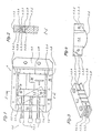
- the device shown in Fig. 1 has a closed, rectangular, flat frame 1, one (on the right in Fig. 1) transverse side is designed as a fixed jaw 1.1. Furthermore, the device has a movable clamping jaw 1.3, which can be inserted into the frame from the outside and is guided on its longitudinal sides 1.2. The jaw 1.3 can on the long sides 1.2 of the frame 1 are clamped and it can be clamped against a flat object W to be held (cf. also FIGS. 2 to 4). The left-hand transverse side 1.4 of the frame 1 in FIG.
- clamping means 1.5 acting on the movable clamping jaw 1.3, which in the present embodiment consists of three screw bolts 1.5.1 each inserted in a threaded hole 1.4.1 of the left-hand transverse side 1.4.
- hydraulically or pneumatically actuated pressure drives can also be used as clamping means 1.5.
- the rigid frame 1 and the precise guidance of the movable clamping jaw 1.3 explained in more detail below enable precise, play-free and distortion-free clamping of the flat object W to be held.
- the movable clamping jaw 1.3 essentially has the shape of a cuboid, which is provided with a groove 1.3.1 on both of its smallest side faces.
- the respective groove base 1.3.2 has an arcuate course (cf. dashed lines in FIGS. 1 and 4).
- the arcuate course of the groove base 1.3.2 of the two opposite grooves is designed in such a way that one groove (upper groove in FIG. 1) has a deep incision in the direction from the workpiece side, which decreases steadily towards the clamping device side, while the bottom of the other groove (bottom in FIG.
- the two grooved ends of the movable jaw 1.3 are each split by a slot 1.3.3 in two prongs 1.3.4 (Fig. 3).
- the slots 1.3.3 each extend from the center line of each groove base 1.3.2 parallel to the largest side surface of the movable jaw 1.3 towards the center thereof. They therefore run approximately in the center plane of the frame 1.
- the associated tines 1.3.4 on both sides of the clamping jaw 1.3 can spring slightly towards one another due to the slot 1.3.3 that forms them, and can thus be braced on the guide bar 1.2.1 of the respective longitudinal frame side 1.2 .
- Each pair of associated tines 1.3.4 has a hole with a common axis running perpendicular to the slot plane. Hole 1.3.5 in one prong is a through hole with smooth walls.
- the other coaxial 1.3.6 hole in the other prong 1.3.4 is a threaded hole.
- the pairs of associated tines 1.3.4, each of which clasp the guide bar 1.2.1 on the inside of the facing longitudinal side of the frame 1.2, can then ge using a countersunk screw 1.3.7 interacting with the threaded bore 1.3.6 against the guide bar 1.2.1 presses and clamped to it without play (cf. in particular Fig. 2).
- the pairs of associated tines 1.3.4 can also be clamped to the associated guide bar 1.2.1 by means of a pressure drive with hydraulic or pneumatic actuation.
- the movable clamping jaw 1.3 can also be designed with a pressure side which is inclined at an angle to the longitudinal sides 1.2 of the frame.
- the surfaces of the clamping jaws 1.1 and 1.3 and also those of the longitudinal sides of the frame 1.2, each of which comes into contact with the side surfaces of the object W, can be designed as special profiles 1.6, as shown in FIG Fig. 4 is shown for a simple example with a circular contour.
- Fig. 1 further shows that the surfaces facing the workpiece W of the fixed jaw 1.1, the movable jaw 1.3 and the guide rails 1.2.1 have incised grooves 1.7, which here has a semicircular cross section and which are perpendicular to the frame plane.
- the grooves can also have another shape, for example a triangular cross section.
- the effective contact surfaces are reduced by these grooves 1.7. However, this makes it possible to keep these contact surfaces cleaner and in particular to remove waste items, dirt such as metal chips etc.
- the wire electrode can also be threaded into these grooves.
- FIG. 5 shows a first example of use of the device according to the invention for the purpose of automated handling of a tightly clamped flat object W when it is processed by the wire electrode D of a wire EDM machine, not shown, in a handling system 2 with a flat slide 2.1 that can be moved in X, Y coordinates according to an earlier patent application by the applicant.
- 5 shows one of two grooves 2.1.1 each formed on the two longitudinal sides of the flat slide 2.1.
- the visible front groove 2.1.1 has a trapezoidal cross-sectional area.
- the other groove (not visible in FIG. 5) is provided with a triangular cross-sectional area.
- the two edge surfaces of the adjacent flat slide side, which are close to the grooves 2.1.1, are designed as finely or precisely machined guide surfaces, while the front groove 2.1.1 has a surface created by milling and less precisely dimensioned.
- the flat slide 2.1 is guided along the guide jaws of a mobile base 2.2 using the grooves 2.1.1, of which only one 2.2.1 is visible in FIG. 5.
- the guide jaw 2.2.1 engaging in the front groove 2.1.1 is provided with a locking device 2.2.2 for locking the flat slide 2.1.
- the base 2.2 can in turn be displaced at right angles to the direction of movement of the flat slide 2.1 by means of guide jaws 2.3, these guide jaws 2.2.3 in turn having grooves 2.3.1. described type of a bar 2.3 are performed.
- the bar 2.3 directed transversely to the flat slide 2.1 is mounted on a frame 2.4.
- the flat slide 2.1 is connected by means of fastening screws 2.1.2 and adjusting screws 2.1.3 to the fixed jaw 1.1 of the box clamp according to FIG. 1.
- FIG. 6 A box clamp of a similar design is also shown in FIG. 6. It is mounted on a pallet 1.9 using holes 1.8 provided in frame 1 and screws 1.8.1 inserted into them.
- the pallet 1.9 has grooves 1.9.1 which are designed similarly to the grooves 2.1.1 of the flat slide 2.1 according to FIG. 5.
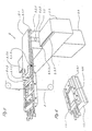
- FIG. 7 shows the use of a box clamp according to FIGS. 1 to 3 in a further handling system 10, which permits processing of an object W clamped in the box clamp from both sides, regardless of whether this object is flat or on both sides the box clamp protrudes.
- the handling system is based on the arrangement according to FIG. 5.
- the box clamp is mounted on a flat slide 12.1 and this is slidably arranged with side grooves 12.1.1 between guide jaws 12.2.1 on the upper longitudinal edges of a mobile base 12.2.
- two slots 12.1.4 are provided in the flat slide 12.1, which run obliquely from the central area of the flat slide 12.1 and each extend to the corresponding groove 12.1.1 via a kink.
- the pedestal 12.2 is then guided by means of further guide jaws 12.2.4 of the same type provided on its lower longitudinal edges in a pair of grooves 12.3.1 which run along the upper longitudinal edges of a bar 12.3 aligned parallel to the movement of the flat slide 12.1 and with regard to their cross-sectional areas and Surface texture are movable to play the grooves 12.1.1 of the flat slide 12.1.
- the beam 12.3 used to guide the base 12.2 in parallel is also provided with a pair of grooves 12.3.2 machined in its lower longitudinal edges, which correspond to those 12.1.1 of the flat slide 12.1 with regard to their cross-sectional area and surface quality.
- the flat slide 2.1 in the arrangement according to FIG. 5 can be replaced by a circular cylindrical shaft which can be guided in a housing and is limited in terms of its axial and rotary movements. It is also in the same arrangement according to FIG. 5 instead of one fold clamp, a multiple frame clamp can also be used, although the direction of movement or clamping of the associated movable clamping jaws should be directed at right angles to the stroke direction of the respective carrier (flat slide, cylindrical shaft, etc.).
- the flat slide 12.1 of the arrangement according to FIGS. 7 and 5 could finally be designed similarly to the beam 12.3 used for parallel guidance with a cross section corresponding to the beam 12.3 and also with four grooves identical to those of the beam. Such a slide would then also be insertable between the guide jaws 12.2.1 of the base 12.2 in a position rotated by 180 ° about its longitudinal axis.
Landscapes
- Engineering & Computer Science (AREA)
- Mechanical Engineering (AREA)
- Jigs For Machine Tools (AREA)
Applications Claiming Priority (2)
| Application Number | Priority Date | Filing Date | Title |
|---|---|---|---|
| CH476/86 | 1986-02-07 | ||
| CH476/86A CH668733A5 (de) | 1986-02-07 | 1986-02-07 | Vorrichtung zur halterung und handhabung eines flachen gegenstandes. |
Publications (1)
| Publication Number | Publication Date |
|---|---|
| EP0237136A1 true EP0237136A1 (fr) | 1987-09-16 |
Family
ID=4187875
Family Applications (2)
| Application Number | Title | Priority Date | Filing Date |
|---|---|---|---|
| EP87200697A Pending EP0237136A1 (fr) | 1986-02-07 | 1987-02-06 | Dispositif de serrage et de manipulation d'un objet plat |
| EP87901052A Expired - Lifetime EP0254741B1 (fr) | 1986-02-07 | 1987-02-06 | Dispositif de retenue et de manipulation d'un objet plat |
Family Applications After (1)
| Application Number | Title | Priority Date | Filing Date |
|---|---|---|---|
| EP87901052A Expired - Lifetime EP0254741B1 (fr) | 1986-02-07 | 1987-02-06 | Dispositif de retenue et de manipulation d'un objet plat |
Country Status (6)
| Country | Link |
|---|---|
| US (1) | US4824085A (fr) |
| EP (2) | EP0237136A1 (fr) |
| JP (1) | JPS63502812A (fr) |
| CH (1) | CH668733A5 (fr) |
| ES (1) | ES2020308B3 (fr) |
| WO (1) | WO1987004651A1 (fr) |
Families Citing this family (17)
| Publication number | Priority date | Publication date | Assignee | Title |
|---|---|---|---|---|
| DE3919078C1 (fr) * | 1989-06-10 | 1990-02-01 | Erowa Ag, Reinach, Ch | |
| US5108080A (en) * | 1989-10-06 | 1992-04-28 | James Lawrence W | Machine tool vise |
| US5033724A (en) * | 1989-10-06 | 1991-07-23 | James Lawrence W | Machine tool vise |
| US5312097A (en) * | 1992-12-21 | 1994-05-17 | Womack Terry R | Double C clamp device |
| US5391230A (en) * | 1993-07-07 | 1995-02-21 | Eastman Kodak Company | Apparatus for holding solid compact medicaments during processing |
| DE4340818C2 (de) * | 1993-12-01 | 2002-03-14 | Mannesmann Sachs Ag | Einspannvorrichtung für ein Werkstück |
| US5551676A (en) * | 1995-03-24 | 1996-09-03 | Gaiser Tool Co. | Dual clamping vise |
| US6761350B1 (en) * | 1996-05-24 | 2004-07-13 | Micron Technology, Inc. | Clamping device |
| US5791640A (en) * | 1996-05-24 | 1998-08-11 | Micron Technology, Inc. | Clamping device |
| JP3037665B2 (ja) * | 1997-11-06 | 2000-04-24 | 株式会社浅井鉄工所 | 小形異形物の掴持装置 |
| US20040168287A1 (en) * | 2001-12-19 | 2004-09-02 | Chun-Tsai Yang | Pressing apparatus for a semiconductor device |
| US6827327B2 (en) * | 2002-07-02 | 2004-12-07 | Cosmo Instruments Co., Ltd. | Flow resistance setting nozzle |
| US20060197269A1 (en) * | 2005-03-04 | 2006-09-07 | Downey Curtis W | Drawer clamp |
| DE102005026346A1 (de) * | 2005-06-08 | 2006-12-14 | Bernhard Brandl | Vorrichtung und Anordnung zum Fixieren von Werkstücken |
| USD803021S1 (en) | 2015-07-30 | 2017-11-21 | Ming Chieh Wu | Pliers |
| CN106807960A (zh) * | 2015-12-02 | 2017-06-09 | 安徽鸿远机电科技有限公司 | 一种钻铣床中拖板 |
| US11925524B1 (en) * | 2023-06-07 | 2024-03-12 | King Faisal University | Dental tooth grasper |
Citations (8)
| Publication number | Priority date | Publication date | Assignee | Title |
|---|---|---|---|---|
| FR547479A (fr) * | 1921-05-10 | 1922-12-13 | étau pour machines-outils | |
| FR764590A (fr) * | 1933-10-20 | 1934-05-24 | Appareil pour faciliter l'assemblage des éléments d'un cadre | |
| CH354045A (de) * | 1957-11-05 | 1961-04-30 | Ehrat Arnold | Einspannvorrichtung für Werkstücke wie Metallschilder usw. beim Gravieren derselben |
| US3239210A (en) * | 1963-07-12 | 1966-03-08 | Ralph L Hustead | Universal drill press and pipe vise |
| FR1482132A (fr) * | 1966-04-12 | 1967-05-26 | Demurger & Cie Ets | étau perfectionné |
| US3665986A (en) * | 1969-10-02 | 1972-05-30 | Jimmie Johnson | Jig for cabinet door construction |
| FR2503009A1 (fr) * | 1981-04-07 | 1982-10-08 | Felix Decool | Ensemble modulaire de serrage |
| EP0143698A1 (fr) * | 1983-11-25 | 1985-06-05 | René Dubois | Support adaptable à des pièces de formes et dimensions variées |
Family Cites Families (5)
| Publication number | Priority date | Publication date | Assignee | Title |
|---|---|---|---|---|
| BE525321A (fr) * | ||||
| US1328492A (en) * | 1919-10-27 | 1920-01-20 | Frank V Carman | Work-holding cradle for spike-hole-plug machines |
| US2518867A (en) * | 1948-04-13 | 1950-08-15 | Laher Spring And Tire Corp | Vehicle spring manufacturing method |
| US2865591A (en) * | 1956-02-23 | 1958-12-23 | Holinshead Alida Viola | Hose-clamp |
| US4412676A (en) * | 1981-12-24 | 1983-11-01 | Black & Decker Inc. | Vise for workbench |
-
1986
- 1986-02-07 CH CH476/86A patent/CH668733A5/de not_active IP Right Cessation
-
1987
- 1987-02-06 JP JP62501163A patent/JPS63502812A/ja active Pending
- 1987-02-06 EP EP87200697A patent/EP0237136A1/fr active Pending
- 1987-02-06 WO PCT/EP1987/000058 patent/WO1987004651A1/fr active IP Right Grant
- 1987-02-06 ES ES87901052T patent/ES2020308B3/es not_active Expired - Lifetime
- 1987-02-06 EP EP87901052A patent/EP0254741B1/fr not_active Expired - Lifetime
- 1987-05-18 US US07/051,535 patent/US4824085A/en not_active Expired - Fee Related
Patent Citations (8)
| Publication number | Priority date | Publication date | Assignee | Title |
|---|---|---|---|---|
| FR547479A (fr) * | 1921-05-10 | 1922-12-13 | étau pour machines-outils | |
| FR764590A (fr) * | 1933-10-20 | 1934-05-24 | Appareil pour faciliter l'assemblage des éléments d'un cadre | |
| CH354045A (de) * | 1957-11-05 | 1961-04-30 | Ehrat Arnold | Einspannvorrichtung für Werkstücke wie Metallschilder usw. beim Gravieren derselben |
| US3239210A (en) * | 1963-07-12 | 1966-03-08 | Ralph L Hustead | Universal drill press and pipe vise |
| FR1482132A (fr) * | 1966-04-12 | 1967-05-26 | Demurger & Cie Ets | étau perfectionné |
| US3665986A (en) * | 1969-10-02 | 1972-05-30 | Jimmie Johnson | Jig for cabinet door construction |
| FR2503009A1 (fr) * | 1981-04-07 | 1982-10-08 | Felix Decool | Ensemble modulaire de serrage |
| EP0143698A1 (fr) * | 1983-11-25 | 1985-06-05 | René Dubois | Support adaptable à des pièces de formes et dimensions variées |
Also Published As
| Publication number | Publication date |
|---|---|
| US4824085A (en) | 1989-04-25 |
| CH668733A5 (de) | 1989-01-31 |
| EP0254741A1 (fr) | 1988-02-03 |
| ES2020308B3 (es) | 1991-08-01 |
| EP0254741B1 (fr) | 1990-12-27 |
| JPS63502812A (ja) | 1988-10-20 |
| WO1987004651A1 (fr) | 1987-08-13 |
Similar Documents
| Publication | Publication Date | Title |
|---|---|---|
| EP0254741B1 (fr) | Dispositif de retenue et de manipulation d'un objet plat | |
| DE4442802C1 (de) | Nutenstein für Spannwerkzeuge | |
| EP2625003B1 (fr) | Fermeture rapide mécanique linéaire | |
| DE19739059A1 (de) | Halteplatte für ein Werkstück | |
| EP0116260B1 (fr) | Dispositif pour fixer un objet | |
| EP0058972A1 (fr) | Outil de coupe pour le travail par enlèvement de copeaux | |
| DE19529004A1 (de) | Werkstückhaltevorrichtung | |
| DE4339271C1 (de) | Haltevorrichtung zur lösbaren Halterung zu bearbeitender Werkstücke | |
| DE1959852A1 (de) | Fluessigkeitszufuehrung fuer Elektroerosionsmaschinen | |
| DE3441968A1 (de) | Gegenstandsfeststeller, -aufspannvorrichtung und bearbeitungsverfahren | |
| DE602004003726T2 (de) | Klemmvorrichtung und Verfahren zum Klemmen eines Teils mit solchen Klemmvorrichtungen | |
| DE102006024880A1 (de) | Werkzeug mit Einstellvorrichtung | |
| EP1563964A1 (fr) | Dispositif auxiliaire pour l'usinage de pièces | |
| EP1402985A2 (fr) | Dispositif de serrage | |
| DE1256514B (de) | Schneidplatte fuer ein spanabhebendes Werkzeug, insbesondere Drehwerkzeug | |
| DE3128198A1 (de) | Verfahren und vorrichtung zum herstellen von nut-feder-verbindungen in werkstuecken | |
| DE19701394C1 (de) | Haltevorrichtung für mehrseitig zu bearbeitende Werkstücke | |
| DE3105181A1 (de) | Schneidwerkzeug | |
| DE2209516A1 (de) | Bohrstange und bohrstangeneinsatz mit bohrstaehlen an beiden enden | |
| DE2322825A1 (de) | Schneidwerkzeug und verfahren zur anformung der schneidkanten desselben | |
| DE3248202C2 (fr) | ||
| DE202005018586U1 (de) | Spannvorrichtung zum Einspannen von Werkstücken | |
| DE3828482A1 (de) | Stoss- oder ziehwerkzeug | |
| EP0765719A1 (fr) | Fraiseuse portative | |
| DE19500946C1 (de) | Winkelverstellbarer Werkstücksitz |
Legal Events
| Date | Code | Title | Description |
|---|---|---|---|
| PUAI | Public reference made under article 153(3) epc to a published international application that has entered the european phase |
Free format text: ORIGINAL CODE: 0009012 |
|
| AK | Designated contracting states |
Kind code of ref document: A1 Designated state(s): ES |
|
| STAA | Information on the status of an ep patent application or granted ep patent |
Free format text: STATUS: REQUEST FOR EXAMINATION WAS MADE |
|
| 17P | Request for examination filed |
Effective date: 19880205 |
|
| RIN1 | Information on inventor provided before grant (corrected) |
Inventor name: BUECHLER, RENE |