EP0236015A2 - Schwingungsisolierungsmittel - Google Patents
Schwingungsisolierungsmittel Download PDFInfo
- Publication number
- EP0236015A2 EP0236015A2 EP87301439A EP87301439A EP0236015A2 EP 0236015 A2 EP0236015 A2 EP 0236015A2 EP 87301439 A EP87301439 A EP 87301439A EP 87301439 A EP87301439 A EP 87301439A EP 0236015 A2 EP0236015 A2 EP 0236015A2
- Authority
- EP
- European Patent Office
- Prior art keywords
- isolating
- zone
- supporting
- base
- isolating means
- Prior art date
- Legal status (The legal status is an assumption and is not a legal conclusion. Google has not performed a legal analysis and makes no representation as to the accuracy of the status listed.)
- Granted
Links
Images

Classifications
-
- F—MECHANICAL ENGINEERING; LIGHTING; HEATING; WEAPONS; BLASTING
- F16—ENGINEERING ELEMENTS AND UNITS; GENERAL MEASURES FOR PRODUCING AND MAINTAINING EFFECTIVE FUNCTIONING OF MACHINES OR INSTALLATIONS; THERMAL INSULATION IN GENERAL
- F16F—SPRINGS; SHOCK-ABSORBERS; MEANS FOR DAMPING VIBRATION
- F16F1/00—Springs
- F16F1/36—Springs made of rubber or other material having high internal friction, e.g. thermoplastic elastomers
- F16F1/3615—Springs made of rubber or other material having high internal friction, e.g. thermoplastic elastomers with means for modifying the spring characteristic
-
- F—MECHANICAL ENGINEERING; LIGHTING; HEATING; WEAPONS; BLASTING
- F16—ENGINEERING ELEMENTS AND UNITS; GENERAL MEASURES FOR PRODUCING AND MAINTAINING EFFECTIVE FUNCTIONING OF MACHINES OR INSTALLATIONS; THERMAL INSULATION IN GENERAL
- F16F—SPRINGS; SHOCK-ABSORBERS; MEANS FOR DAMPING VIBRATION
- F16F1/00—Springs
- F16F1/36—Springs made of rubber or other material having high internal friction, e.g. thermoplastic elastomers
- F16F1/42—Springs made of rubber or other material having high internal friction, e.g. thermoplastic elastomers characterised by the mode of stressing
- F16F1/44—Springs made of rubber or other material having high internal friction, e.g. thermoplastic elastomers characterised by the mode of stressing loaded mainly in compression
-
- F—MECHANICAL ENGINEERING; LIGHTING; HEATING; WEAPONS; BLASTING
- F16—ENGINEERING ELEMENTS AND UNITS; GENERAL MEASURES FOR PRODUCING AND MAINTAINING EFFECTIVE FUNCTIONING OF MACHINES OR INSTALLATIONS; THERMAL INSULATION IN GENERAL
- F16F—SPRINGS; SHOCK-ABSORBERS; MEANS FOR DAMPING VIBRATION
- F16F15/00—Suppression of vibrations in systems; Means or arrangements for avoiding or reducing out-of-balance forces, e.g. due to motion
- F16F15/02—Suppression of vibrations of non-rotating, e.g. reciprocating systems; Suppression of vibrations of rotating systems by use of members not moving with the rotating systems
- F16F15/04—Suppression of vibrations of non-rotating, e.g. reciprocating systems; Suppression of vibrations of rotating systems by use of members not moving with the rotating systems using elastic means
- F16F15/08—Suppression of vibrations of non-rotating, e.g. reciprocating systems; Suppression of vibrations of rotating systems by use of members not moving with the rotating systems using elastic means with rubber springs ; with springs made of rubber and metal
-
- G—PHYSICS
- G12—INSTRUMENT DETAILS
- G12B—CONSTRUCTIONAL DETAILS OF INSTRUMENTS, OR COMPARABLE DETAILS OF OTHER APPARATUS, NOT OTHERWISE PROVIDED FOR
- G12B3/00—Details of movements not otherwise provided for
- G12B3/04—Suspensions
-
- F—MECHANICAL ENGINEERING; LIGHTING; HEATING; WEAPONS; BLASTING
- F16—ENGINEERING ELEMENTS AND UNITS; GENERAL MEASURES FOR PRODUCING AND MAINTAINING EFFECTIVE FUNCTIONING OF MACHINES OR INSTALLATIONS; THERMAL INSULATION IN GENERAL
- F16F—SPRINGS; SHOCK-ABSORBERS; MEANS FOR DAMPING VIBRATION
- F16F2230/00—Purpose; Design features
- F16F2230/0047—Measuring, indicating
-
- F—MECHANICAL ENGINEERING; LIGHTING; HEATING; WEAPONS; BLASTING
- F16—ENGINEERING ELEMENTS AND UNITS; GENERAL MEASURES FOR PRODUCING AND MAINTAINING EFFECTIVE FUNCTIONING OF MACHINES OR INSTALLATIONS; THERMAL INSULATION IN GENERAL
- F16F—SPRINGS; SHOCK-ABSORBERS; MEANS FOR DAMPING VIBRATION
- F16F2236/00—Mode of stressing of basic spring or damper elements or devices incorporating such elements
- F16F2236/04—Compression
Definitions
- This invention relates to vibration isolation means and is particularly applicable to metrological apparatus such as rate tables, angular measuring systems and apparatus for the measurement of profile errors including roundness, straightness and surface texture.
- the invention is aimed at providing an improved vibration damping or isolating arrangement.
- the invention provides a vibration isolation arrangement comprising a chassis adapted to be mounted on a support such as a floor and provided with an isolation means between the chassis and the floor, and a frame or support mounted on the chassis by further isolation means.
- a vibration isolation arrangement comprising a chassis adapted to be mounted on a support such as a floor and provided with an isolation means between the chassis and the floor, and a frame or support mounted on the chassis by further isolation means.
- the first and second isolation means have different natural frequencies.
- the invention provides an apparatus for supporting a member, such as a transducer, sensitive to vibration, in which damping means is arranged so that vibrational energy is dissipated primarily by vibration in a direction in which the effect of the vibration on said member is at least low or preferably a minimum.
- the metrological apparatus comprises a massive main frame or chassis 2 having four legs 4 (only three of which can be seen in Figure 1) each of which is provided at its bottom with an isolating mount 6 which supports the apparatus on the floor (not shown in Figure 1).
- a base 8 is mounted on the main frame 2 by means of four further isolating mounts 10 and carries a motor driven turntable 12 for supporting a workpiece (not shown) to be measured and a vertical column 14.
- a motor driven carriage 16 is vertically movable, as indicated by arrow A, on the column 14.
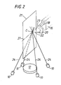
- the tip of the stylus 22 ca n be moved any where within a rectangular zone of operation 21 which is illustrated in Figure 2.
- the zone of operation 21 is located substantially in a vertically extending radial plane of the turntable 12.
- a knuckle joint 23 permits the transducer 20 and stylus 22 to be moved, relative to the arm 18, from the horizontal position shown in Figure 1 to a position in which the stylus 22 is vertical.
- the knuckle joint 23 is such that the tip of the stylus 22 remains substantially in the plane 21 regardless of whether the stylus is in the horizontal or the vertical position.
- a workpiece whose surface is to be measured is placed upon the turntable 12 and then the turntable 12, carriage 16 and arm 18 are moved, preferably under the control of a computer system (not shown) so that the surface of the workpiece is traversed by the stylus 22 whereby the transducer 20 outputs a signal representative of surface characteristics.
- the apparatus under description is manufactured to the highest standards of precision and is intended for detecting the minutest variations in the parameters to be measured, and in particular is intended to take measurements of the order of a micron or less. Accordingly, the minutest of vibrations experienced by the transducer 20 or stylus 22 may invalidate the measurements being made.
- the isolating mounts 6 and 10 are provided and arranged for substantially eliminating the transmission of externally originating vibrations to the transducer 20 or stylus 22. This is achieved in the embodiment illustrated in the drawings by a combination of two measures. One of these measures involves arranging that the natural frequency at which the massive frame 2 may oscillate on the isolating mounts 6 is different from that at which the base 8 may oscillate on the isolating mounts 10.
- the in situ natural frequency of the mounts 10 is different from that of the mounts 6.
- the in situ natural frequency of the mounts 6 is lower than that of the mounts 10.
- the in situ natural frequency of the mounts 6 may be in the range 9 to 11Hz and that of the mounts 10 may be in the range 15 to 20Hz, preferably in the ratio range of about 1:1.5 to 1:2.
- the second of the measures involves utilising for the mounts 10 members which have a higher stiffness along a line 24 passing through the zone of operation 21 of the stylus 22 than the stiffness in a direction transverse thereto.
- the ratio of these two stiffnesses is 5:1.
- the lines 24 all pass through a point C located substantially within the zone of operation 21 at substantially the centre thereof.
- the stylus 22 may be moved horizontally and vertically it will not always be located precisely at the point at which vibrations have the minimal effect i.e. the susceptibility of the apparatus to vibration will vary to a degree according to the position of the stylus within its zone of operation 21. Nevertheless, the arrangement under description does provide a major improvement compared to machines at present available and is such that the apparatus may operate in locations, such as adjacent a production line, where hitherto it has not been possible to operate metrological apparatus due to susceptibility to vibration.
- the centre of gravity of the structure comprising the base 8, turntable 12, column 14, carriage 16, arm 18 and transducer and stylus 20, 22 should be located as low as possible.
- the embodiment illustrated may be constru cted such that the centre of gravity of this structure is at a level about two or more inches below the surface of the turntable 12.
- the actual location of the centre of gravity will move as the carriage 16 and/or arm 18 move.
- the centre of gravity of the structure including the workpiece will depend upon the nature of the workpiece and its position and orientation on the turntable.
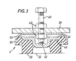
- the mount 6 comprises a resilient pad 30, preferably of neoprene rubber, which rests on the floor 32 and which is bonded at 34 to the inside of a steel bell-shaped housing 36.
- the housing 36 is secured to the underside of a horizontal plate 38 which forms a part of the leg 4, by means of a bolt 40, the lower end 42 of which engages the inside surface of a steel flanged cup 44 to which the pad 30 is bonded at 46.
- the bolt 40 is provided with lock nuts 48 and arranged so that levelling of the apparatus may be achieved by adjustment of the bolts 40, such adjustment causing adjustment of the degree to which the pads 30 project below the housing 36.
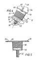
- each mount 10 is secured between a bracket 50 of the main frame 2 having a support surface 52 at right angles to the direction 24, and a bracket 54 of the table 8 having a support surface 56 parallel to the surface 52.
- the mount 10 comprises a frustoconical resilient pad 58 , peferably of neoprene rubber, having an axial stiffness greater than its transverse stiffness preferably in the ratio 5:1 and arranged with its narrow end lowermost and its axis coincident with line 24.
- a circular steel plate 60 is bonded to the lower end of the pad 58 and has a stud 62 welded thereto and passing through an opening 64 in the bracket 50, which is of larger diameter than the stud 62 to permit adjustment.
- a nut 63 on the stud 62 secures the plate 60 to the surface 52 of bracket 50.
- a plate 66 is bonded to the upper end of the pad 58 and is secured by studs 68, passing through openings 70, to the surface 56 of the bracket 54.
- Isolating mounts 6 and 10 as illustrated in the drawings may be obtained from Cementation (Muffelite) Limited of Hersham, Walton-on-Thames, Surrey, England.
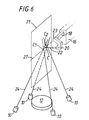
- the mounts 10 are arranged so that the lines 24 substantially intersect at two points C1 and C2, rather than at a single point as in the previous embodiment.
- the points C1 and C2 are spaced apart on a horizontal line 27 which substantially bisects the rectangular zone of operation 21 of the stylus 22 with the points C1 and C2 being substantially equispaced on opposite sides of the centre C of the rectangular zone 21.
- each line 24 may pass through the zone of operation 21 at a point different from each of the other lines 24.
- the lines 24 should pass through the zone 21 near to the centre thereof, this is not essential, but it is preferred in order to minimise the effects of vibration throughout the whole of the zone of operation 21 of the stylus 22.
- the transducer is mounted for movement horizontally in only o ne direction
- the zone of operation of the transducer will be a solid volume rather than a plane area and the mounts 10 would be arranged so that the lines 24 pass through this solid volume of operation.
- the invention can be applied to instruments in which the workpiece is supported on a stationary table, rather than a rotary table, and the transducer is caused to traverse the surface of the workpiece solely by movement of the transducer while the workpiece is held stationary.
- the invention is particularly applicable to metrological apparatus and has been illustrated therein, it may also be applied to apparatus in which a member other than a stylus/transducer is provided for performing an operation on or in relation to the surface of an object.
- a member other than a stylus/transducer is provided for performing an operation on or in relation to the surface of an object.
- An example of such other apparatus is a machine tool. When applied to a machine tool, the lines 24 would pass through the zone in which the machining member, such as a grinding wheel, is operable.
- mount 58 in the preferred embodiment is frustoconical and mounted with the wider portion uppermost, it would be possible to use this type of mount the other way up.
- Forms of mount other than the mount 58 could be employed.
- four mounts 58 have been provided, it is within the scope of the invention that any form of isolating means having a higher stiffness in one direction than in a transverse direction may be employed.
Applications Claiming Priority (2)
| Application Number | Priority Date | Filing Date | Title |
|---|---|---|---|
| GB08604596A GB2186946A (en) | 1986-02-25 | 1986-02-25 | Vibration isolation means |
| GB8604596 | 1986-02-25 |
Publications (3)
| Publication Number | Publication Date |
|---|---|
| EP0236015A2 true EP0236015A2 (de) | 1987-09-09 |
| EP0236015A3 EP0236015A3 (en) | 1988-03-30 |
| EP0236015B1 EP0236015B1 (de) | 1990-12-12 |
Family
ID=10593610
Family Applications (1)
| Application Number | Title | Priority Date | Filing Date |
|---|---|---|---|
| EP87301439A Expired - Lifetime EP0236015B1 (de) | 1986-02-25 | 1987-02-19 | Schwingungsisolierungsmittel |
Country Status (9)
| Country | Link |
|---|---|
| US (1) | US4798006A (de) |
| EP (1) | EP0236015B1 (de) |
| JP (1) | JP2587228B2 (de) |
| CN (1) | CN87101585A (de) |
| DD (1) | DD259056A5 (de) |
| DE (1) | DE3766629D1 (de) |
| DK (1) | DK72487A (de) |
| GB (1) | GB2186946A (de) |
| SU (1) | SU1623573A3 (de) |
Cited By (5)
| Publication number | Priority date | Publication date | Assignee | Title |
|---|---|---|---|---|
| EP0379859A1 (de) * | 1989-01-03 | 1990-08-01 | The Perkin-Elmer Corporation | Schwingungsdämpfendes Lagersystem |
| WO1991001558A1 (en) * | 1989-07-20 | 1991-02-07 | Paolo Russo | Stratiform, inelastic, deformable, statically stable structure, for deadening undesirable natural and imposed vibrations, comprising at least a layer comprised by a particle solid phase and by a massive consistency phase, particularly for provision of tripodal supports |
| EP0596837A2 (de) * | 1992-10-28 | 1994-05-11 | F.I.M.E. - FABBRICA ITALIANA MOTORI ELETTRICI - S.r.l. | Ein baryzentrisches Lager für das Ausgleichen einer Motor-Rotoreinheit auf einem Kessel mit hermetischen Druckbrennkammern |
| EP0860627A1 (de) * | 1997-02-20 | 1998-08-26 | Unisorb Inc | Einsatz mit fester horizontaler Eigenfrequenz für schwingungsdämpfendes Lager |
| CN112498708A (zh) * | 2020-06-01 | 2021-03-16 | 重庆宗申航空发动机制造有限公司 | 一种航空无人机以及航空发动机安装支架 |
Families Citing this family (24)
| Publication number | Priority date | Publication date | Assignee | Title |
|---|---|---|---|---|
| DE3723466A1 (de) * | 1987-07-16 | 1989-01-26 | Barry Controls Gmbh | Nachstelleinrichtung zum korrigieren der lage einer maschine |
| GB8808282D0 (en) * | 1988-04-08 | 1988-05-11 | Lk Tool Co Ltd | Support assemblies |
| US5042162A (en) * | 1989-02-10 | 1991-08-27 | Brown & Sharpe Manufacturing Company | Coordinate measuring machine with vibration dampening system |
| US4958437A (en) * | 1989-02-10 | 1990-09-25 | Brown & Sharpe Manufacturing Company | Coordinate measuring machine with vibration damper |
| DE3911341C1 (de) * | 1989-04-07 | 1990-10-11 | Wild Leitz Gmbh, 6330 Wetzlar, De | |
| US5068971A (en) * | 1990-03-23 | 1991-12-03 | Simco Industries, Inc. | Adjustable portable coordinate measuring machine |
| US5280677A (en) * | 1990-05-17 | 1994-01-25 | Canon Kabushiki Kaisha | Positioning mechanism |
| US5535524A (en) * | 1995-01-27 | 1996-07-16 | Brown & Sharpe Manufacturing Company | Vibration damper for coordinate measuring machine |
| US6785217B1 (en) | 1998-01-27 | 2004-08-31 | Wistron Corporation | Method and device for reducing vibration of a high speed disk drive |
| US6354558B1 (en) * | 1998-11-20 | 2002-03-12 | Carrier Corporation | Compressor mounting |
| ITMI20011241A1 (it) * | 2001-06-13 | 2002-12-13 | Advanced Technologies S R L | Metodo per la calibrazione e taratura di sensori in una stazione di assemblaggio e stazione di assemblaggio |
| US6871561B2 (en) * | 2002-03-07 | 2005-03-29 | Northrop Grumman Corporation | Isolator and assembly configuration |
| JP4071227B2 (ja) * | 2004-09-28 | 2008-04-02 | 株式会社新川 | ボンディング装置 |
| JP2006125924A (ja) * | 2004-10-27 | 2006-05-18 | Tokyo Seimitsu Co Ltd | 真円度/円柱形状測定装置 |
| DE102005018326B4 (de) * | 2005-04-20 | 2009-11-12 | Siemens Ag | Steuerungsverfahren zur Bewegungsführung eines hinsichtlich seiner Halteposition bewegbaren, dabei zu einer Schwingung anregbaren Röntgenstrahlers und/oder Röntgenempfängers eines Röntgenuntersuchungssystems |
| US7866021B2 (en) * | 2006-05-31 | 2011-01-11 | Jac Property Holdings, Llc | Methods and assemblies for manufacturing components |
| DE102006061003B4 (de) * | 2006-12-22 | 2009-03-26 | Mähner, Bernward | Vorrichtung zum Prüfen eines Prüfobjekts, insbesondere eines Reifens, mittels eines zerstörungsfreien Messverfahrens |
| CN102305685B (zh) * | 2011-08-19 | 2015-01-14 | 中国兵器工业集团第七○研究所 | 油压传感器隔振装置 |
| JPWO2013125231A1 (ja) * | 2012-02-22 | 2015-07-30 | 株式会社安震 | 重量物の免震構造および免震施工法 |
| CN104713721B (zh) * | 2015-04-10 | 2017-06-16 | 株洲时代新材料科技股份有限公司 | 隔振器系统动态性能测试试验平台及其测试方法 |
| RU2664783C2 (ru) * | 2016-11-24 | 2018-08-22 | Общество с ограниченной ответственностью "НТ-МДТ" | Устройство подвижки |
| CN110126999B (zh) * | 2019-05-13 | 2020-06-23 | 中国人民解放军国防科技大学 | 一种基于船舶的海洋气象监测装置 |
| CN112997024A (zh) * | 2019-12-31 | 2021-06-18 | 深圳市大疆创新科技有限公司 | 运动传感器模组及可移动平台 |
| CN112483631B (zh) * | 2020-11-06 | 2021-11-26 | 安徽江淮汽车集团股份有限公司 | 连接结构和变速器 |
Citations (8)
| Publication number | Priority date | Publication date | Assignee | Title |
|---|---|---|---|---|
| GB553793A (en) * | 1941-11-29 | 1943-06-07 | Metalastik Ltd | Improvements relating to resilient mountings for instruments and machines |
| FR932779A (fr) * | 1943-12-30 | 1948-04-01 | Bristol Aeroplane Co Ltd | Suspension pour corps soumis à des vibrations |
| GB658898A (en) * | 1949-04-21 | 1951-10-17 | Dunlop Rubber Co | Equiflexible mountings |
| GB665079A (en) * | 1949-02-21 | 1952-01-16 | Lord Mfg Co | Improvements in resilient mounting systems |
| US3490728A (en) * | 1966-11-10 | 1970-01-20 | Philips Corp | Resilient supporting device |
| US3565386A (en) * | 1969-02-19 | 1971-02-23 | Gen Motors Corp | Mount for a body and coupling unit therefor |
| GB1452280A (en) * | 1973-03-02 | 1976-10-13 | British United Shoe Machinery | Measuring machines |
| EP0100785A1 (de) * | 1982-08-13 | 1984-02-22 | International Business Machines Corporation | Hochleistungsvibrationsfilter |
Family Cites Families (5)
| Publication number | Priority date | Publication date | Assignee | Title |
|---|---|---|---|---|
| US3625466A (en) * | 1970-08-20 | 1971-12-07 | Marshall Research & Dev Corp | Vibration isolator |
| JPS589781Y2 (ja) * | 1976-08-12 | 1983-02-22 | 東海ゴム工業株式会社 | 自動車用エンジン支持装置 |
| JPS6015807B2 (ja) * | 1980-04-17 | 1985-04-22 | 日産自動車株式会社 | エンジンのマウンテイング装置 |
| DE3125681C2 (de) * | 1981-06-30 | 1983-04-21 | Mauser-Werke Oberndorf Gmbh, 7238 Oberndorf | Koordinaten-Meßmaschine |
| JPS59108901A (ja) * | 1982-12-13 | 1984-06-23 | Mitsutoyo Mfg Co Ltd | 測定機の支持台 |
-
1986
- 1986-02-25 GB GB08604596A patent/GB2186946A/en not_active Withdrawn
-
1987
- 1987-02-13 DK DK072487A patent/DK72487A/da not_active Application Discontinuation
- 1987-02-19 DE DE8787301439T patent/DE3766629D1/de not_active Expired - Lifetime
- 1987-02-19 EP EP87301439A patent/EP0236015B1/de not_active Expired - Lifetime
- 1987-02-23 DD DD87300116A patent/DD259056A5/de not_active IP Right Cessation
- 1987-02-24 US US07/018,021 patent/US4798006A/en not_active Expired - Lifetime
- 1987-02-24 JP JP62042458A patent/JP2587228B2/ja not_active Expired - Lifetime
- 1987-02-24 SU SU874202001A patent/SU1623573A3/ru active
- 1987-02-25 CN CN198787101585A patent/CN87101585A/zh active Pending
Patent Citations (8)
| Publication number | Priority date | Publication date | Assignee | Title |
|---|---|---|---|---|
| GB553793A (en) * | 1941-11-29 | 1943-06-07 | Metalastik Ltd | Improvements relating to resilient mountings for instruments and machines |
| FR932779A (fr) * | 1943-12-30 | 1948-04-01 | Bristol Aeroplane Co Ltd | Suspension pour corps soumis à des vibrations |
| GB665079A (en) * | 1949-02-21 | 1952-01-16 | Lord Mfg Co | Improvements in resilient mounting systems |
| GB658898A (en) * | 1949-04-21 | 1951-10-17 | Dunlop Rubber Co | Equiflexible mountings |
| US3490728A (en) * | 1966-11-10 | 1970-01-20 | Philips Corp | Resilient supporting device |
| US3565386A (en) * | 1969-02-19 | 1971-02-23 | Gen Motors Corp | Mount for a body and coupling unit therefor |
| GB1452280A (en) * | 1973-03-02 | 1976-10-13 | British United Shoe Machinery | Measuring machines |
| EP0100785A1 (de) * | 1982-08-13 | 1984-02-22 | International Business Machines Corporation | Hochleistungsvibrationsfilter |
Cited By (7)
| Publication number | Priority date | Publication date | Assignee | Title |
|---|---|---|---|---|
| EP0379859A1 (de) * | 1989-01-03 | 1990-08-01 | The Perkin-Elmer Corporation | Schwingungsdämpfendes Lagersystem |
| WO1991001558A1 (en) * | 1989-07-20 | 1991-02-07 | Paolo Russo | Stratiform, inelastic, deformable, statically stable structure, for deadening undesirable natural and imposed vibrations, comprising at least a layer comprised by a particle solid phase and by a massive consistency phase, particularly for provision of tripodal supports |
| EP0596837A2 (de) * | 1992-10-28 | 1994-05-11 | F.I.M.E. - FABBRICA ITALIANA MOTORI ELETTRICI - S.r.l. | Ein baryzentrisches Lager für das Ausgleichen einer Motor-Rotoreinheit auf einem Kessel mit hermetischen Druckbrennkammern |
| EP0596837A3 (en) * | 1992-10-28 | 1994-08-10 | Fime Fab It Motor Elett | A barycentric support for balancing the motor-rotor unit on airtight combustion chamber boilers. |
| EP0860627A1 (de) * | 1997-02-20 | 1998-08-26 | Unisorb Inc | Einsatz mit fester horizontaler Eigenfrequenz für schwingungsdämpfendes Lager |
| CN112498708A (zh) * | 2020-06-01 | 2021-03-16 | 重庆宗申航空发动机制造有限公司 | 一种航空无人机以及航空发动机安装支架 |
| CN112498708B (zh) * | 2020-06-01 | 2022-02-08 | 重庆宗申航空发动机制造有限公司 | 一种航空无人机以及航空发动机安装支架 |
Also Published As
| Publication number | Publication date |
|---|---|
| DE3766629D1 (de) | 1991-01-24 |
| SU1623573A3 (ru) | 1991-01-23 |
| US4798006A (en) | 1989-01-17 |
| DK72487A (da) | 1987-08-26 |
| JP2587228B2 (ja) | 1997-03-05 |
| EP0236015B1 (de) | 1990-12-12 |
| DD259056A5 (de) | 1988-08-10 |
| GB8604596D0 (en) | 1986-04-03 |
| GB2186946A (en) | 1987-08-26 |
| DK72487D0 (da) | 1987-02-13 |
| JPS62209307A (ja) | 1987-09-14 |
| EP0236015A3 (en) | 1988-03-30 |
| CN87101585A (zh) | 1987-12-02 |
Similar Documents
| Publication | Publication Date | Title |
|---|---|---|
| US4798006A (en) | Vibration isolation means | |
| US4135392A (en) | Equipment mounting and monitoring system | |
| EP0255574B1 (de) | Koordinatenmessmaschine | |
| US5067348A (en) | Rotary member measuring apparatus with improved support bed | |
| KR900007886B1 (ko) | 브리지타입 좌표 측정기 | |
| GB2163256A (en) | Surface tracer | |
| US4958437A (en) | Coordinate measuring machine with vibration damper | |
| EP0027060B1 (de) | Koordinaten-Messmaschine | |
| EP0426674B1 (de) | Unterstützungsvorrichtung | |
| US3845561A (en) | Measuring head system | |
| JPH0127364B2 (de) | ||
| JPH04505796A (ja) | 補助溜め部を有する気体支承体 | |
| US3188869A (en) | Unbalance indication system | |
| US3815425A (en) | System for wheel balancing | |
| JP2711429B2 (ja) | スラスト試験装置 | |
| JP4841142B2 (ja) | ねじの許容差検査のための方法およびシステム | |
| KR101272860B1 (ko) | 공작기계의 테이블 회전 정밀도 측정장치 | |
| EP0194002B1 (de) | Brückenartige Koordinatenmessmaschine | |
| JPS644126B2 (de) | ||
| RU209692U1 (ru) | Лабораторный стенд для проведения прецизионных измерений перемещений элементов конструкции зданий и сооружений от внешних динамических воздействий | |
| CA1061138A (en) | Self-leveling static wheel balancer | |
| CN219388510U (zh) | 测量设备的气浮减震结构 | |
| US6105445A (en) | Method of obtaining an error signal in a positioning device | |
| RU2158895C1 (ru) | Способ измерения геометрической формы номинально круглой цилиндрической детали и устройство для его реализации | |
| RU2003938C1 (ru) | Координатна измерительна машина мостового типа |
Legal Events
| Date | Code | Title | Description |
|---|---|---|---|
| PUAI | Public reference made under article 153(3) epc to a published international application that has entered the european phase |
Free format text: ORIGINAL CODE: 0009012 |
|
| AK | Designated contracting states |
Kind code of ref document: A2 Designated state(s): CH DE GB IT LI SE |
|
| PUAL | Search report despatched |
Free format text: ORIGINAL CODE: 0009013 |
|
| AK | Designated contracting states |
Kind code of ref document: A3 Designated state(s): CH DE GB IT LI SE |
|
| 17P | Request for examination filed |
Effective date: 19880915 |
|
| 17Q | First examination report despatched |
Effective date: 19890615 |
|
| ITF | It: translation for a ep patent filed |
Owner name: ING. ZINI MARANESI & C. S.R.L. |
|
| GRAA | (expected) grant |
Free format text: ORIGINAL CODE: 0009210 |
|
| AK | Designated contracting states |
Kind code of ref document: B1 Designated state(s): CH DE GB IT LI SE |
|
| REF | Corresponds to: |
Ref document number: 3766629 Country of ref document: DE Date of ref document: 19910124 |
|
| ITTA | It: last paid annual fee | ||
| PLBE | No opposition filed within time limit |
Free format text: ORIGINAL CODE: 0009261 |
|
| STAA | Information on the status of an ep patent application or granted ep patent |
Free format text: STATUS: NO OPPOSITION FILED WITHIN TIME LIMIT |
|
| 26N | No opposition filed | ||
| EAL | Se: european patent in force in sweden |
Ref document number: 87301439.3 |
|
| REG | Reference to a national code |
Ref country code: GB Ref legal event code: 732E |
|
| REG | Reference to a national code |
Ref country code: CH Ref legal event code: PUE Owner name: RANK TAYLOR HOBSON LIMITED TRANSFER- TAYLOR HOBSON |
|
| PGFP | Annual fee paid to national office [announced via postgrant information from national office to epo] |
Ref country code: SE Payment date: 20010125 Year of fee payment: 15 |
|
| PGFP | Annual fee paid to national office [announced via postgrant information from national office to epo] |
Ref country code: GB Payment date: 20010205 Year of fee payment: 15 |
|
| PGFP | Annual fee paid to national office [announced via postgrant information from national office to epo] |
Ref country code: CH Payment date: 20010212 Year of fee payment: 15 |
|
| PGFP | Annual fee paid to national office [announced via postgrant information from national office to epo] |
Ref country code: DE Payment date: 20010425 Year of fee payment: 15 |
|
| REG | Reference to a national code |
Ref country code: GB Ref legal event code: IF02 |
|
| PG25 | Lapsed in a contracting state [announced via postgrant information from national office to epo] |
Ref country code: GB Free format text: LAPSE BECAUSE OF NON-PAYMENT OF DUE FEES Effective date: 20020219 |
|
| PG25 | Lapsed in a contracting state [announced via postgrant information from national office to epo] |
Ref country code: SE Free format text: LAPSE BECAUSE OF NON-PAYMENT OF DUE FEES Effective date: 20020220 |
|
| PG25 | Lapsed in a contracting state [announced via postgrant information from national office to epo] |
Ref country code: LI Free format text: LAPSE BECAUSE OF NON-PAYMENT OF DUE FEES Effective date: 20020228 Ref country code: CH Free format text: LAPSE BECAUSE OF NON-PAYMENT OF DUE FEES Effective date: 20020228 |
|
| PG25 | Lapsed in a contracting state [announced via postgrant information from national office to epo] |
Ref country code: DE Free format text: LAPSE BECAUSE OF NON-PAYMENT OF DUE FEES Effective date: 20020903 |
|
| EUG | Se: european patent has lapsed |
Ref document number: 87301439.3 |
|
| GBPC | Gb: european patent ceased through non-payment of renewal fee |
Effective date: 20020219 |
|
| REG | Reference to a national code |
Ref country code: CH Ref legal event code: PL |
|
| PG25 | Lapsed in a contracting state [announced via postgrant information from national office to epo] |
Ref country code: IT Free format text: LAPSE BECAUSE OF NON-PAYMENT OF DUE FEES Effective date: 20050219 |