EP0235373B1 - Schutzhelm, insbesondere für Benutzer von Kraftfahrzeugen - Google Patents
Schutzhelm, insbesondere für Benutzer von Kraftfahrzeugen Download PDFInfo
- Publication number
- EP0235373B1 EP0235373B1 EP86116483A EP86116483A EP0235373B1 EP 0235373 B1 EP0235373 B1 EP 0235373B1 EP 86116483 A EP86116483 A EP 86116483A EP 86116483 A EP86116483 A EP 86116483A EP 0235373 B1 EP0235373 B1 EP 0235373B1
- Authority
- EP
- European Patent Office
- Prior art keywords
- air guide
- ventilation openings
- protective helmet
- adjacent
- narrow
- Prior art date
- Legal status (The legal status is an assumption and is not a legal conclusion. Google has not performed a legal analysis and makes no representation as to the accuracy of the status listed.)
- Expired
Links
- 230000001681 protective effect Effects 0.000 title claims description 30
- 238000009423 ventilation Methods 0.000 claims description 34
- TVEXGJYMHHTVKP-UHFFFAOYSA-N 6-oxabicyclo[3.2.1]oct-3-en-7-one Chemical compound C1C2C(=O)OC1C=CC2 TVEXGJYMHHTVKP-UHFFFAOYSA-N 0.000 description 1
- 230000000903 blocking effect Effects 0.000 description 1
- 230000007423 decrease Effects 0.000 description 1
- 230000001419 dependent effect Effects 0.000 description 1
- 230000002349 favourable effect Effects 0.000 description 1
- 239000003292 glue Substances 0.000 description 1
- 238000002347 injection Methods 0.000 description 1
- 239000007924 injection Substances 0.000 description 1
Images

Classifications
-
- A—HUMAN NECESSITIES
- A42—HEADWEAR
- A42B—HATS; HEAD COVERINGS
- A42B3/00—Helmets; Helmet covers ; Other protective head coverings
- A42B3/04—Parts, details or accessories of helmets
- A42B3/0493—Aerodynamic helmets; Air guiding means therefor
-
- A—HUMAN NECESSITIES
- A42—HEADWEAR
- A42B—HATS; HEAD COVERINGS
- A42B3/00—Helmets; Helmet covers ; Other protective head coverings
- A42B3/04—Parts, details or accessories of helmets
- A42B3/28—Ventilating arrangements
- A42B3/281—Air ducting systems
Definitions
- the invention relates to a protective helmet of the type mentioned in the preamble of claim 1 and resulting from DE-A 31 37 680.
- the air guiding device is designed as a V-shaped channel located below the ventilation openings. This has its greatest depth on the front of the chin guard, which decreases steadily from there to the rear. Due to this design of the air guiding device, when the motorcyclist is in an approximately normal head posture - which is shown in FIG. 5 - only the air flow which flows approximately horizontally into the protective helmet due to dynamic pressure reaches the helmet interior via the ventilation openings. However, the amount of air flowing into the latter is usually not sufficient for good helmet ventilation.
- GB-A 21 34 774 discloses an integral protective helmet which is provided on the front with a number of ventilation openings on its chin guard. Since the known protective helmet has no air guiding device in the area of the ventilation openings, only the approximately horizontally acting air flow acting on the protective helmet by dynamic pressure can reach the helmet interior through the ventilation openings, even when the motorcycle driver is in a favorable head position. However, the air flow flowing through the visor to the lower edge of the helmet is not used at all for helmet internal ventilation.
- the object of the invention is therefore to provide a protective helmet of the type mentioned in the preamble of claim 1 such that, in addition to the air flow acting approximately horizontally on the protective helmet, the air flow flowing downward through the viewing window is effective for helmet internal ventilation regardless of the respective inclination of the user head is exploited.
- the air guiding device consists of an air guiding part protruding beyond the adjacent contour of the chin guard, the narrow side of which underneath serves as the inflow surface for the air flow flowing down through the viewing window, it is dammed up in the area of the ventilation openings and introduced into the helmet interior via these.
- This is particularly advantageous in the case of a motorcycle with a windshield - which can be located on a motorcycle fairing - since the air flow flowing over the windshield of the protective helmet is divided at the upper edge region of the viewing opening and partly downwards via the helmet tip and partly via the viewing window and thus gets into the helmet interior in the manner mentioned.
- the height of the narrow side of the air guide part below corresponds approximately to the wall thickness of the chin guard and is thus approximately 5 mm (feature of patent claim 2).
- the air guiding part is designed like a frame with a rectangular outline, the narrow side lying below having the greatest height and thus blocking the air flow flowing downward through the viewing window.
- a protective helmet is usually provided with a plurality of ventilation openings lying next to one another
- a plurality of frame-like air guiding parts can also be arranged next to one another, each enclosing ventilation openings lying one above the other (features of patent claims 4 and 5).
- the air flowing into the protective helmet is thus optimally introduced into the interior thereof, for which the design of the inner walls of the narrow sides of the air guiding parts is advantageous. If a protective helmet has only one ventilation opening or a plurality of ventilation openings lying one above the other, these are of course only surrounded by a single frame-like air guiding part.
- the air guiding part according to the invention can advantageously also be retrofitted in a simple manner.
- a separate insert part consisting of one or more frame-like air guiding parts lying next to one another is expediently made of plastic, which can be non-detachably connected to the chin guard.
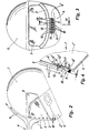
- the motorcycle driver's protective helmet 1 shown in FIGS. 1 to 3 has a viewing opening 2, which can be covered by a viewing window 3. This is mounted on a protective helmet 1 together with a chin guard 4 on two opposite bearing bolts 5 so that it can be swiveled up and down. As can be seen in FIGS. 3 and 4, the chin guard 4 has a truncated cone-shaped section 4 '. This is provided below the edge of the viewing opening 2 and in the central longitudinal region of the chin guard 4, each with three ventilation openings 7 one above the other; six rows of ventilation openings 7 are arranged side by side. The ventilation openings 7 can run parallel or obliquely to the edge of the viewing opening 2.
- the motorcycle shown in Fig. 1 has a Mo Door trim 8 on which there is a windshield 9 on the front.
- the air stream a which acts on the windshield 9 when the motorcycle is being driven is conducted to approximately the upper edge region of the viewing opening 2 and is divided there into an air stream b flowing over the helmet tip and into an air stream c flowing downward via the viewing window 3. Even if the motorcycle does not have a windshield 9, the protective helmet 1 is acted upon by the air flow approximately as described.
- the air flow c flowing down over the region of the viewing pane 3 is introduced via the narrow side 11 below of a frame-like air guiding part 10 while passing the ventilation openings 7 into the helmet interior 1 '(FIGS. 2 and 4).
- the frame-like air guiding part 10 has a rectangular shape and consists of an underlying and an overhead narrow side 11 or 12, the underlying narrow side 11 having a height h of approximately 5 mm - which corresponds approximately to the wall thickness of the chin guard 4 -, while the height h ' the narrow side 12 above is about 2-3 mm.
- the two narrow sides 11 and 12 are each connected to one another by external webs 13, each of which tapers upwards in a wedge shape. Since the narrow side 11 of the air guiding part 10 lying below has a height h of approximately 5 mm, it protrudes like a nose in cross section beyond the adjacent contour of the chin guard 4, thereby ensuring optimal air introduction into the helmet interior 1 '.
- the protective helmet 1 As shown in FIG. 3, in the protective helmet 1 according to the invention, six rows of ventilation openings 7 are arranged side by side on the frustoconical section 4 'of his chin guard 4; three ventilation openings 7 lie one above the other in each row. Since these are each surrounded by an air guiding part 10, six air guiding parts 10 lie next to one another, a web 13 of the air guiding part 10 being located between two adjacent rows of ventilation openings 7. If a protective helmet 1 only has ventilation openings 7 lying one above the other, these are of course only surrounded by a single air guiding part 10.
- the air guiding parts 10 are expediently formed in one piece on the protective helmet 1 by appropriate design of the injection mold. However, it is also conceivable to prefabricate one or more adjacent air guide parts 10 as a separate, one-piece insert made of plastic or the like and to glue them onto an existing protective helmet 1 in the area of ventilation openings 7.
Landscapes
- Physics & Mathematics (AREA)
- Fluid Mechanics (AREA)
- Helmets And Other Head Coverings (AREA)
Description
- Die Erfindung bezieht sich auf einen Schutzhelm der im Oberbegriff des Patentanspruchs 1 genannten und aus der DE-A 31 37 680 hervorgehenden Art.
- Bei dem bekannten Schutzhelm ist die Luftleiteinrichtung als eine unterhalb den Belüftungsöffnungen liegende, V-förmige Rinne ausgebildet. Diese hat an der Frontseite des Kinnschutzes ihre größte Tiefe, welche sich von dort nach hinten stetig verringert. Aufgrund dieser Gestaltung der Luftleiteinrichtung gelangt über diese bei etwa normaler Kopfhaltung des Motorradfahrers - welche in Fig. 5 dargestellt ist - lediglich der etwa waagrecht den Schutzhelm durch Staudruck anströmende Luftstrom über die Belüftungsöffnungen in den Helminnenraum. Die derart in letzteren einströmende Luftmenge ist jedoch für eine gute Helmbelüftung meistens nicht ausreichend.
- Femer ist ind er GB-A 21 34 774 ein Integral-Schutzhelm offenbart, der an seinem Kinnschutz frontseitig mit einer Anzahl von Belüftungsöffnungen versehen ist. Da der bekannte Schutzhelm im Bereich der Belüftungsöffnungen keine Luftleiteinrichtung aufweist, kann selbst bei günstiger Kopfhaltung des Motorradfahrers nur der etwa waagrecht den Schutzhelm durch Staudruck beaufschlagende Luftstrom über die Belüftungsöffnungen in den Helminnenraum gelangen. Der über die Sichtscheibe zum unteren Helmrand hin fließende Luftstrom wird jedoch für die Helminnenbelüftung überhaupt nicht ausgenutzt.
- Aufgabe der Erfindung ist es daher, einen Schutzhelm der im Oberbegriff des Patentanspruchs 1 genannten Art derart auszubilden, daß neben dem etwa waagrecht den Schutzhelm beaufschlagenden Luftstrom auch der über die Sichtscheibe abwärts fließende Luftstrom und zwar unabhängig von der jeweiligen Neigungslage des Benutzerkopfes wirkungsvoll für die Helminnenbelüftung ausgenutzt wird.
- Zur Lösung der Aufgabe sind die im kennzeichnenden Teil des Patentanspruchs 1 dargelegten Merkmale vorgesehen.
- Besondere Ausführungsarten der Erfindung sind in den abhängigen Ansprüchen 2-6 aufgeführt.
- Da die Luftleiteinrichtung erfindungsgemäß aus einem über die angrenzende Kontur des Kinnschutzes hinausragenden Luftleitteil besteht, dessen untenliegende Schmalseite als Anströmfläche für den über die Sichtscheibe abwärts fließenden Luftstrom dient, wird dieser im Bereich der Belüftungsöffnungen aufegestaut und über diese in den Helminnenraum eingeleitet. Dies ist insbesondere auch bei einem Motorrad mit einer Windschutzscheibe - welche sich an einer Motorradverkleidung befinden kann - von Vorteil, da der über die Windschutzscheibe den Schutzhelm anströmende Luftstrom am oberen Randbereich der Sichtöffnung geteilt wird und teils über die Helmkuppe, teils über die Sichtscheibe abwärts strömt und damit in erwähnter Weise in den Helminnenraum gelangt.
- Die Höhe der untenliegenden Schmalseite des Luftleitteils entspricht in etwa der Wanddicke des Kinnschutzes und beträgt damit etwa 5 mm (Merkmal des Patentanspruchs 2).
- Bei einem Schutzhelm mit mehreren nebeneinanderliegenden Belüftungsöffnungen erstreckt sich die untenliegende Schmalseite des Luftleitteils über den untenliegenden Rand sämtlicher Belüftungsöffnungen (Merkmal des Patentanspruchs 3).
- Nach den Merkmalen des Patentanspruchs 4 u.a. ist das Luftleitteil bei rechteckförmigem Umriß rahmenartig gestaltet, wobei die untenliegende Schmalseite die größte Höhe hat und damit den über die Sichtscheibe abwärts fließenden Luftstrom aufstaut. Nachdem ein Schutzhelm üblicherweise mit mehreren nebeneinanderliegenden Belüftungsöffnungen versehen ist, können auch mehrere rahmenarige Luftleitteile nebeneinanderliegend angeordnet sein, die jeweils übereinanderliegende Belüftungsöffnungen umschließen (Merkmale der Patentansprüche 4 und 5). Damit wird die den Schutzhelm anströmende Luft in optimaler Weise in dessen Innenraum eingeleitet, wofür auch die im Patentanspruch 5 dargelegte Gestaltung der Innenwandungen der Schmalseiten der Luftleitteile vorteilhaft ist. Falls ein Schutzhelm nur eine Belüftungsöffnung oder mehrere übereinanderliegende Belüftungsöffnungen aufweist, sind diese natürlich nur von einem einzigen rahmenartigen Luftleitteil umgeben.
- Das erfindungsgemäße Luftleitteil kann vorteilhafterweise auch in einfacher Weise nachgerüstet werden. Ein aus einem oder mehreren nebeneinanderliegenden rahmenartigen Luftleitteilen bestehendes, separates Einsatzteil wird dabei zweckmäßigerweise aus Kunststoff gefertigt, das mit dem Kinnschutz unlösbar verbindbar ist.
- Ein Ausführungsbeispiel der Erfindung ist in der Zeichnung dargestellt und wird im folgenden erläutert. Es zeigt:
- Fig. 1 ein Motorrad mit einer Vollverkleidung, dessen Fahrer einen erfindungsgemäßen Schutzheim trägt,
- Fig. 2 eine Einzelansicht eines erfindungsgemäßen Schutzhelms in größerer Darstellung,
- Fig. 3 einen Schutzhelm in Vorderansicht,
- Fig. 4 einen Schnitt längs der Linie IV-IV in Fig. 3 in größerer Darstellung.
- Der in den Figuren 1 bis 3 dargestellte Motorradfahrer-Schutzhelm 1 hat eine Sichtöffnung 2, welche von einer Sichtscheibe 3 überdeckbar ist. Diese ist zusammen mit einem Kinnschutz 4 an zwei gegenüberliegenden Lagerbolzen 5 hoch- und niederschwenkbar am Schutzhelm 1 gelagert. Wie in den Figuren 3 und 4 ersichtlich, hat der Kinnschutz 4 einen kegelstumpfförmig nach oben einwärts verlaufenden Abschnitt 4'. Dieser ist unterhalb des Randes der Sichtöffnung 2 sowie im Längsmittelbereich des Kinnschutzes 4 mit jeweils drei übereinanderliegenden Belüftungsöffnungen 7 versehen; dabei sind sechs Reihen von Belüftungsöffnungen 7 nebeneinanderliegend angeordnet. Die Belüftungsöffnungen 7 können dabei parallel oder auch schräg zum Rand der Sichtöffnung 2 verlaufen.
- Das in Fig. 1 dargestellte Motorrad hat eine Motorradverkleidung 8, an der sich frontseitig eine Windschutzscheibe 9 befindet. Der beim Fahren des Motorrads die Windschutzscheibe 9 beaufschlagende Luftstrom a wird bis etwa zum oberen Randbereich der Sichtöffnung 2 geleitet und teilt sich dort in einen über die Helmkuppe fließenden Luftstrom b sowie in einen über die Sichtscheibe 3 abwärts strömenden Luftstrom c. Auch wenn das Motorrad keine Windschutzscheibe 9 hat, wird der Schutzhelm 1 etwa wie dargelegt vom Luftstrom beaufschlagt.
- Der über den Bereich der Sichtscheibe 3 abwärts fließende Luftstrom c wird über die untenliegende Schmalseite 11 eines rahmenartigen Luftleitteils 10 unter Passage der Belüftungsöffnungen 7 in den Helminnenraum 1' eingeleitet (Fig. 2 und 4). Das rahmenartige Luftleitteil 10 ist rechteckförmig gestaltet und besteht dabei aus einer untenliegenden und obenliegenden Schmalseite 11 bzw. 12, wobei die untenliegende Schmalseite 11 eine Höhe h von etwa 5 mm aufweist - was etwa der Wanddicke des Kinnschutzes 4 entspricht -, während die Höhe h' der obenliegenden Schmalseite 12 etwa 2-3 mm beträgt. Die beiden Schmalseiten 11 und 12 sind jeweils von außenliegenden Stegen 13 miteinander verbunden, welche sich jeweils keilförmig nach oben verjüngen. Da die untenliegende Schmalseite 11 des Luftleitteils 10 eine Höhe h von etwa 5 mm hat, ragt sie über die angrenzende Kontur des Kinnschutzes 4 im Querschnitt nasenartig hinaus, wodurch eine optimale Lufteinleitung in den Helminnenraum 1' gewährleistet ist.
- Wie Fig. 3 zeigt, sind beim erfindungsgemäßen Schutzhelm 1 am kegelstumpfförmigen Abschnitt 4' seines Kinnschutzes 4 sechs Reihen von Belüftungsöffnungen 7 im Mittelbereich von dessen Längserstreckung nebeneinanderliegend angeordnet; dabei liegen in jeder Reihe drei Belüftungsöffnungen 7 übereinander. Da diese jeweils von einem Luftleitteil 10 umgeben sind, liegen sechs Luftleitteile 10 nebeneinaner, wobei zwischen zwei nebeneinanderliegenden Reihen von Belüftungsöffnungen 7 jeweils ein Steg 13 des Luftleitteils 10 liegt. Falls ein Schutzhelm 1 nur übereinanderliegende Belüftungsöffnungen 7 hat, werden diese natürlich nur von einem einzigen Luftleitteil 10 umgeben.
- In Fig. 4 ist zu ersehen, daß die einander zugewandten, jeweils an eine der Belüftungsöffnungen 7 angrenzenden Innenwandungen der untenliegenden und obenliegenden Schmalseiten 11 und 12 in einem Vertikalschnitt jeweils als schräg von oben außen nach innen zu den Belüftungsöffnungen 7 hin verlaufende Anströmflächen 11' und 12' ausgebildet sind. Durch diese Maßnahme ist gewährleistet, daß beim Fahrbetrieb des Motorrads der über die Sichtscheibe 3 abwärts fließende Luftstrom c in aerodynamisch optimaler Weise und gezielt duch die Luftleitteile 10 und über die Belüftungsöffnungen 7 in den Helminnenraum 1' eingeleitet wird.
- Bei Neuanfertigung eines Schutzhelms 1 werden die Luftleitteile 10 durch entsprechende Gestaltung der Spritzgießform zweckmäßigerweise einstückig am Schutzhelm 1 ausgebildet. Es ist jedoch auch denkbar, eines oder mehrere nebeneinanderliegende Luftleitteile 10 als ein separates, einteiliges Einsatzteil laus Kunststoff oder dgl. vorzufertigen und auf einen vorhandenen Schutzhelm 1 im Bereich von Belüftungsöffnungen 7 aufzukleben.
Claims (6)
Applications Claiming Priority (2)
| Application Number | Priority Date | Filing Date | Title |
|---|---|---|---|
| DE3607223A DE3607223C1 (de) | 1986-03-05 | 1986-03-05 | Schutzhelm,insbesondere fuer Benutzer von Kraftfahrzeugen |
| DE3607223 | 1986-03-05 |
Publications (2)
| Publication Number | Publication Date |
|---|---|
| EP0235373A1 EP0235373A1 (de) | 1987-09-09 |
| EP0235373B1 true EP0235373B1 (de) | 1989-11-23 |
Family
ID=6295562
Family Applications (1)
| Application Number | Title | Priority Date | Filing Date |
|---|---|---|---|
| EP86116483A Expired EP0235373B1 (de) | 1986-03-05 | 1986-11-27 | Schutzhelm, insbesondere für Benutzer von Kraftfahrzeugen |
Country Status (2)
| Country | Link |
|---|---|
| EP (1) | EP0235373B1 (de) |
| DE (2) | DE3607223C1 (de) |
Families Citing this family (1)
| Publication number | Priority date | Publication date | Assignee | Title |
|---|---|---|---|---|
| FI89872C (fi) * | 1992-09-08 | 1993-12-10 | Alpo Ikonen | Hjaelm - andningsskyddskombination och foerfarande foer anvaendning av den |
Family Cites Families (6)
| Publication number | Priority date | Publication date | Assignee | Title |
|---|---|---|---|---|
| US4115874A (en) * | 1977-02-21 | 1978-09-26 | Masahiro Hasegawa | Helmet for use in riding vehicles |
| US4354285A (en) * | 1980-10-06 | 1982-10-19 | Drag Specialties, Inc. | Face shield and helmet |
| JPS5937324U (ja) * | 1982-09-03 | 1984-03-09 | 本田技研工業株式会社 | ヘルメツト |
| IT1170108B (it) * | 1983-02-14 | 1987-06-03 | Pier Luigi Nava | Casco con visiera ribaltabile, particolarmente per usi sportivi |
| DE3325250A1 (de) * | 1983-07-13 | 1985-01-24 | Hein Gericke GmbH & Co KG, 4000 Düsseldorf | Integral-sturzhelm fuer fahrzeugfahrer |
| DE8415797U1 (de) * | 1984-05-24 | 1985-09-12 | Voss, Hans, 6950 Mosbach | Schutzhelm für Fahrer |
-
1986
- 1986-03-05 DE DE3607223A patent/DE3607223C1/de not_active Expired
- 1986-11-27 DE DE8686116483T patent/DE3667017D1/de not_active Expired
- 1986-11-27 EP EP86116483A patent/EP0235373B1/de not_active Expired
Also Published As
| Publication number | Publication date |
|---|---|
| EP0235373A1 (de) | 1987-09-09 |
| DE3667017D1 (en) | 1989-12-28 |
| DE3607223C1 (de) | 1987-07-30 |
Similar Documents
| Publication | Publication Date | Title |
|---|---|---|
| DE3148725C1 (de) | Schutzhelm,insbes,fuer Benutzer von Kraftfahrzeugen | |
| DE69103018T2 (de) | Aerodynamischer scheibenwischer. | |
| DE69115201T2 (de) | Integralhelm für Motorradfahrer mit einer Vorrichtung zum verhindern des beschlagens der Sichtscheibe. | |
| EP0100042B1 (de) | Schutzhelm, insbesondere für Motorradfahrer | |
| DE8229801U1 (de) | Schutzhelm, insbesondere Motorradhelm | |
| DE3137680A1 (de) | Gesichtsschild fuer einen sturzhelm | |
| DE3325601C2 (de) | Schutzhelm für Motorradfahrer | |
| EP0327730A1 (de) | Luftleitvorrichtung für Radbremsen eines Kraftfahrzeugs | |
| DE3203738A1 (de) | Vorrichtung zum abdecken von gleit- und fuehrungsschienen bei werkzeugmaschinen | |
| DE2600616A1 (de) | Motorradverkleidung | |
| DE2838451C3 (de) | Vorrichtung zum Verhindern des Abhebens von Scheibenwischerblättern infolge Fahrtwind bei Kraftfahrzeugen | |
| DE3701081A1 (de) | Defroster-anlage fuer windschutzscheibe | |
| DE2830027B2 (de) | Vertikal geführter Hochgeschwindigkeits-Stromabnehmer | |
| DE3344706C2 (de) | Schutzhelm für Motorradfahrer oder dergleichen | |
| DE3607223C1 (de) | Schutzhelm,insbesondere fuer Benutzer von Kraftfahrzeugen | |
| EP0135812A2 (de) | Schutzhelm, insbesondere Integralhelm für Motorradfahrer | |
| DE4405926C2 (de) | Fahrzeugscheibenwischer | |
| EP1755763B1 (de) | Tropfenabscheideranordnung | |
| DE3341407C2 (de) | Helm,insbesondere für Sportzwecke | |
| DE2409364C2 (de) | Vorrichtung zum Verhindern der Verschmutzung der Seitenscheiben von Fahrzeugen, insbesondere Kraftfahrzeugen | |
| EP0050745B1 (de) | Kraftfahrzeug, insbesondere Personenkraftwagen, mit einer Bugverkleidung unter der Stossstange | |
| DE19739388C2 (de) | Deckel zum Verschließen einer Fahrzeugkarosserieöffnung | |
| DE3316699C2 (de) | Schneestaubabweiser für einen Schneepflug | |
| DE19821358B4 (de) | Lüfterleiste für einen einem beweglichen Glasdach an einem Fahrzeug zugeordneten verschiebbaren Sonnenschutz | |
| DE2552915A1 (de) | Aussenrueckblickspiegel fuer fahrzeuge |
Legal Events
| Date | Code | Title | Description |
|---|---|---|---|
| PUAI | Public reference made under article 153(3) epc to a published international application that has entered the european phase |
Free format text: ORIGINAL CODE: 0009012 |
|
| AK | Designated contracting states |
Kind code of ref document: A1 Designated state(s): DE FR GB IT |
|
| 17P | Request for examination filed |
Effective date: 19870716 |
|
| 17Q | First examination report despatched |
Effective date: 19881123 |
|
| GRAA | (expected) grant |
Free format text: ORIGINAL CODE: 0009210 |
|
| AK | Designated contracting states |
Kind code of ref document: B1 Designated state(s): DE FR GB IT |
|
| GBT | Gb: translation of ep patent filed (gb section 77(6)(a)/1977) | ||
| ET | Fr: translation filed | ||
| REF | Corresponds to: |
Ref document number: 3667017 Country of ref document: DE Date of ref document: 19891228 |
|
| ITF | It: translation for a ep patent filed | ||
| PLBE | No opposition filed within time limit |
Free format text: ORIGINAL CODE: 0009261 |
|
| STAA | Information on the status of an ep patent application or granted ep patent |
Free format text: STATUS: NO OPPOSITION FILED WITHIN TIME LIMIT |
|
| 26N | No opposition filed | ||
| ITTA | It: last paid annual fee | ||
| PGFP | Annual fee paid to national office [announced via postgrant information from national office to epo] |
Ref country code: DE Payment date: 19921031 Year of fee payment: 7 |
|
| PGFP | Annual fee paid to national office [announced via postgrant information from national office to epo] |
Ref country code: GB Payment date: 19921126 Year of fee payment: 7 |
|
| PGFP | Annual fee paid to national office [announced via postgrant information from national office to epo] |
Ref country code: FR Payment date: 19921127 Year of fee payment: 7 |
|
| PG25 | Lapsed in a contracting state [announced via postgrant information from national office to epo] |
Ref country code: GB Effective date: 19931127 |
|
| GBPC | Gb: european patent ceased through non-payment of renewal fee |
Effective date: 19931127 |
|
| PG25 | Lapsed in a contracting state [announced via postgrant information from national office to epo] |
Ref country code: FR Effective date: 19940729 |
|
| PG25 | Lapsed in a contracting state [announced via postgrant information from national office to epo] |
Ref country code: DE Effective date: 19940802 |
|
| REG | Reference to a national code |
Ref country code: FR Ref legal event code: ST |
|
| PG25 | Lapsed in a contracting state [announced via postgrant information from national office to epo] |
Ref country code: IT Free format text: LAPSE BECAUSE OF NON-PAYMENT OF DUE FEES;WARNING: LAPSES OF ITALIAN PATENTS WITH EFFECTIVE DATE BEFORE 2007 MAY HAVE OCCURRED AT ANY TIME BEFORE 2007. THE CORRECT EFFECTIVE DATE MAY BE DIFFERENT FROM THE ONE RECORDED. Effective date: 20051127 |