EP0226914A2 - Fixation de radiateur pour moteur à combustion interne, en particulier dans des véhicules automobiles - Google Patents
Fixation de radiateur pour moteur à combustion interne, en particulier dans des véhicules automobiles Download PDFInfo
- Publication number
- EP0226914A2 EP0226914A2 EP86116965A EP86116965A EP0226914A2 EP 0226914 A2 EP0226914 A2 EP 0226914A2 EP 86116965 A EP86116965 A EP 86116965A EP 86116965 A EP86116965 A EP 86116965A EP 0226914 A2 EP0226914 A2 EP 0226914A2
- Authority
- EP
- European Patent Office
- Prior art keywords
- support
- point
- brackets
- radiator
- support points
- Prior art date
- Legal status (The legal status is an assumption and is not a legal conclusion. Google has not performed a legal analysis and makes no representation as to the accuracy of the status listed.)
- Granted
Links
- 238000002485 combustion reaction Methods 0.000 title claims abstract description 6
- 230000001154 acute effect Effects 0.000 claims description 2
- 238000010137 moulding (plastic) Methods 0.000 claims 1
- 230000036316 preload Effects 0.000 abstract description 2
- 238000009420 retrofitting Methods 0.000 description 5
- 230000007797 corrosion Effects 0.000 description 4
- 238000005260 corrosion Methods 0.000 description 4
- 238000004519 manufacturing process Methods 0.000 description 3
- XLYOFNOQVPJJNP-UHFFFAOYSA-N water Substances O XLYOFNOQVPJJNP-UHFFFAOYSA-N 0.000 description 3
- 238000006243 chemical reaction Methods 0.000 description 1
- 238000012986 modification Methods 0.000 description 1
- 230000004048 modification Effects 0.000 description 1
Images

Classifications
-
- B—PERFORMING OPERATIONS; TRANSPORTING
- B60—VEHICLES IN GENERAL
- B60K—ARRANGEMENT OR MOUNTING OF PROPULSION UNITS OR OF TRANSMISSIONS IN VEHICLES; ARRANGEMENT OR MOUNTING OF PLURAL DIVERSE PRIME-MOVERS IN VEHICLES; AUXILIARY DRIVES FOR VEHICLES; INSTRUMENTATION OR DASHBOARDS FOR VEHICLES; ARRANGEMENTS IN CONNECTION WITH COOLING, AIR INTAKE, GAS EXHAUST OR FUEL SUPPLY OF PROPULSION UNITS IN VEHICLES
- B60K11/00—Arrangement in connection with cooling of propulsion units
- B60K11/02—Arrangement in connection with cooling of propulsion units with liquid cooling
- B60K11/04—Arrangement or mounting of radiators, radiator shutters, or radiator blinds
Definitions
- the invention relates to a radiator attachment for internal combustion engines, in particular in motor vehicles, of a type with the features according to the preamble of patent claim 1.
- a known radiator attachment of this type according to DE-OS 26 34 990 contains lower and upper brackets which are attached to the body support points by means of screw or welded connections. Such fastening points are at risk of corrosion and, if the radiator of different sizes is installed, must have different fastening points on the body. This requires different training or difficult retrofitting of the fastening points both for the initial assembly and for possible retrofitting.
- the object of the invention is to avoid the difficulties described above and to design the radiator attachment so that both the risk of corrosion is largely avoided and the optional and retrofitting of different sized radiators is possible without retrofitting the body attachment points.
- the invention provides the characterizing features of claim 1 in the type of radiator attachment described above.
- differently dimensioned brackets can be attached to the body support points in an easy-to-use manner, secured and locked in place, and braced, and radiators of different sizes can be optionally and subsequently attached without additional components and conversion measures using these brackets.
- the largely flat support of the plastic brackets on the body support points largely excludes the risk of corrosion of these fastening points.
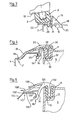
- a cooler 1 for an internal combustion engine, not shown, is fastened to lower longitudinal beams 2 and 3 on both sides and to an upper cross member 4 of the body of a motor vehicle, not shown.
- the two-sided water boxes 5 and 6 of the cooler 1 are each formed with a receiving pin 7 and 8 for a buffer-shaped elastic bearing element 9, which is supported against a flat annular support surface as the lower cooler support points 10.
- the water boxes 5 and 6 each have an opening which is open at the top Support surface 12 formed, each receiving an elastic bearing element 13.
- bracket 18, 19 and 20 or 21 are arranged between the lower and upper elastic bearing elements 9 and 13 and respectively assigned lower and upper body support points 14 and 15 or 16 and 17 on the lower side members 2 and 3 or on the upper cross member 4, there is a bracket 18, 19 and 20 or 21 arranged.
- These brackets 18 to 21 each consist of a one-piece plastic molded part made of fiber-reinforced high-strength plastic.
- Each bracket 18, 19, 20 and 21 is by means of a three-point support with its own elastic pretension and / or under elastic pretension of the entire fastening arrangement with the two body support points 14 or 16 and 17 as a two-point support and the radiator support point 10 or 11 connected.
- One of the two body support points 14, 15, 16 and 17 of each console is designed as a catch in such a way that, in conjunction with the overall design of the console and the second support point, an elastic bias of the console to secure its attachment to the body support points results.
- a lower pan-shaped receptacle 22 is formed onto the lower brackets 18 and 19 for supporting the bearing element 9.
- this bracket is formed with a lower snap-in support 23 which engages behind a recess 24 in the side member 2 and fills it largely without play.
- the lower support point in the longitudinal direction of the longitudinal beam 2 is arranged twice in succession at a sufficient distance.
- the upper support point 15 of the bracket 18 is also provided with a recess 25 on the upper side of the side member 2 and with a hook-like latch 26 of the bracket 18, which is arranged at the free end of an elastic arm 27 of the bracket 18.
- the assignment of these components is dimensionally matched so that when the latch 26 engages, the bracket 18 is fastened to the side member 2 under pretension.
- the body Abs support parts 14 for the console 19 also consist of two recesses 28 and 29 in the top of the side member 3.
- the bracket 19 are formed locking elements 30 and 31 which engage in the recesses 28 and 29, these fill completely and under Lock pre-tension.
- the console 19 lies flat on the top of the longitudinal beam 3 in such a way that a stable support of the cooler 1 at the support point 14 is ensured on all sides.
- the upper bracket 20 engages with a tongue-shaped extension 32 in a position-securing manner in a corresponding opening in the bearing element 13.
- the extension 32 is surrounded on all sides with a support surface 33 between the bracket 20 and the bearing element 13.
- the bracket 20 extends by means of a support arm 34 and 35 to the body support points 16 and 17, respectively.
- the elasticity of the support arms 34 and 35 largely causes the prestressed fastening of the bracket 20 in one from the end of the support arm 35 clearance-free penetrated and undercut recess 36 in the cross member 4 and the locking of the hook-shaped end of the support arm 34 with a boundary edge 37 of the cross member 4.
- the elastic bias of the bracket 20 also causes an elastic bias of the bearing member 13 and thus the compensation of manufacturing tolerances in the area Mounting the cooler 1.
- the console 120 according to FIG. 5 corresponds essentially to the design of the console 20 according to FIG. 4. Deviations exist in the design of the tongue-shaped extension 132 with a cylindrical end region which, in conjunction with a play in the bearing element 113, causes the console 120 to pivot relative to Water box 6 allows.
- the second support point 117 is formed flat on the cross member 104.
- the bracket 120 has two particularly elastic support arms 135 and 138 for the support point 117, which converge towards the support point 117 at an acute angle and whose free ends 135 'and 138' are in Support the area of the support point 117 against each other in an adjustable manner by means of a set of teeth 139.
- the described radiator attachment for internal combustion engines, particularly in motor vehicles, enables the use of different radiator sizes both in the case of new production and after retrofitting, simply by using different brackets between unchanged support points on body parts and on the radiator.
- the elastic locking of the brackets to the body parts without metallic fastening parts and connection points prevents corrosion at these connection points.
- the radiator attachment can be easily assembled without tools by hand or by means of automatic assembly machines, and dismantling only requires a simple tool, such as a screwdriver, to release the locking engagement of the brackets.
Applications Claiming Priority (2)
| Application Number | Priority Date | Filing Date | Title |
|---|---|---|---|
| DE19853545141 DE3545141A1 (de) | 1985-12-19 | 1985-12-19 | Kuehler-befestigung fuer brennkraftmaschinen, insbesondere in kraftfahrzeugen |
| DE3545141 | 1985-12-19 |
Publications (3)
| Publication Number | Publication Date |
|---|---|
| EP0226914A2 true EP0226914A2 (fr) | 1987-07-01 |
| EP0226914A3 EP0226914A3 (en) | 1987-09-23 |
| EP0226914B1 EP0226914B1 (fr) | 1989-01-25 |
Family
ID=6288967
Family Applications (1)
| Application Number | Title | Priority Date | Filing Date |
|---|---|---|---|
| EP86116965A Expired EP0226914B1 (fr) | 1985-12-19 | 1986-12-06 | Fixation de radiateur pour moteur à combustion interne, en particulier dans des véhicules automobiles |
Country Status (5)
| Country | Link |
|---|---|
| US (1) | US4773496A (fr) |
| EP (1) | EP0226914B1 (fr) |
| JP (1) | JPS62143717A (fr) |
| DE (2) | DE3545141A1 (fr) |
| ES (1) | ES2006696B3 (fr) |
Families Citing this family (14)
| Publication number | Priority date | Publication date | Assignee | Title |
|---|---|---|---|---|
| GB2198096A (en) * | 1986-12-02 | 1988-06-08 | Ford Motor Co | Mounting arrangement |
| FR2628038B1 (fr) * | 1988-03-03 | 1990-08-10 | Peugeot | Procede et agencement de fixation pour le montage d'un radiateur de vehicule automobile |
| JPH0754018Y2 (ja) * | 1988-07-06 | 1995-12-13 | マツダ株式会社 | ラジエータの支持構造 |
| DE3901193C1 (fr) * | 1989-01-17 | 1990-02-22 | Bayerische Motoren Werke Ag, 8000 Muenchen, De | |
| DE4025661A1 (de) * | 1990-08-14 | 1992-02-20 | Bayerische Motoren Werke Ag | Vorrichtung zur mittelbaren halterung eines an strukturteilen montierbaren aggregates, insbesondere eines kuehlermoduls am aufbau von kraftfahrzeugen |
| US5163505A (en) * | 1992-03-27 | 1992-11-17 | General Motors Corporation | Heater core retaining system |
| US5605200A (en) * | 1995-04-03 | 1997-02-25 | General Motors Corporation | Self attaching upper radiator mount |
| US5668351A (en) * | 1996-02-09 | 1997-09-16 | General Motors Corporation | Conduit housing for vehicle engine compartment having a flexible lip that extends into airflow sealing engagement with the radiation |
| GB9609440D0 (en) * | 1996-05-04 | 1996-07-10 | Ford Motor Co | Radiator and condenser assembly |
| FR2793741B1 (fr) * | 1999-05-20 | 2001-08-10 | Peguform France | Dispositif de fixation d'un radiateur sur un support d'un vehicule |
| FR2802595B1 (fr) * | 1999-12-20 | 2002-08-09 | Valeo Thermique Moteur Sa | Dispositif de montage d'un equipement, en particulier d'un module d'echange de chaleur, sur un vehicule automobile |
| US6675921B2 (en) * | 2001-04-30 | 2004-01-13 | Custom Molders, Inc. | Vehicle radiator support structure |
| DE10252879A1 (de) * | 2002-11-12 | 2004-05-27 | Behr Gmbh & Co. Kg | Befestigungsvorrichtung, insbesondere zur Befestigung eines Kühlmoduls an einem Fahrzeugrahmen |
| US8235155B2 (en) * | 2009-06-02 | 2012-08-07 | Deere & Company | Radiator mounting arrangement on utility vehicle |
Citations (6)
| Publication number | Priority date | Publication date | Assignee | Title |
|---|---|---|---|---|
| DE2634990A1 (de) * | 1976-08-04 | 1978-02-09 | Audi Nsu Auto Union Ag | Kuehlerbefestigung fuer kraftfahrzeuge |
| EP0126855A1 (fr) * | 1983-05-26 | 1984-12-05 | Dr.Ing.h.c. F. Porsche Aktiengesellschaft | Fixation de radiateur pour véhicules |
| EP0132844A2 (fr) * | 1983-07-26 | 1985-02-13 | Toyota Jidosha Kabushiki Kaisha | Support supérieur pour un radiateur |
| FR2561998A1 (fr) * | 1984-03-27 | 1985-10-04 | Renault | Dispositif de fixation par ressort de pression d'un radiateur sur un element de structure |
| US4579184A (en) * | 1983-09-02 | 1986-04-01 | Mazda Motor Corporation | Resiliently mounted radiator assembly |
| DE3608898A1 (de) * | 1985-03-20 | 1986-10-02 | Nissan Motor Co., Ltd., Yokohama, Kanagawa | Halterung fuer einen autokuehler |
Family Cites Families (6)
| Publication number | Priority date | Publication date | Assignee | Title |
|---|---|---|---|---|
| JPS5152068Y2 (fr) * | 1971-03-23 | 1976-12-13 | ||
| US3929201A (en) * | 1974-03-01 | 1975-12-30 | Gen Motors Corp | Radiator mountings for internal combustion engines |
| DE2557967C3 (de) * | 1975-12-22 | 1978-12-14 | Daimler-Benz Ag, 7000 Stuttgart | Kühlerbefestigung eines Kraftfahrzeuges |
| JPS5828023B2 (ja) * | 1980-03-19 | 1983-06-13 | 中小企業事業団 | ダイカスト機の金型交換装置 |
| JPS5828023U (ja) * | 1981-08-19 | 1983-02-23 | 三菱自動車工業株式会社 | ラジエ−タの支持装置 |
| JPS6011317B2 (ja) * | 1982-07-10 | 1985-03-25 | トヨタ自動車株式会社 | ラジエ−タの支持装置 |
-
1985
- 1985-12-19 DE DE19853545141 patent/DE3545141A1/de active Granted
-
1986
- 1986-12-06 EP EP86116965A patent/EP0226914B1/fr not_active Expired
- 1986-12-06 ES ES86116965T patent/ES2006696B3/es not_active Expired - Lifetime
- 1986-12-06 DE DE8686116965T patent/DE3661893D1/de not_active Expired
- 1986-12-16 JP JP61297830A patent/JPS62143717A/ja active Granted
- 1986-12-16 US US06/942,403 patent/US4773496A/en not_active Expired - Fee Related
Patent Citations (6)
| Publication number | Priority date | Publication date | Assignee | Title |
|---|---|---|---|---|
| DE2634990A1 (de) * | 1976-08-04 | 1978-02-09 | Audi Nsu Auto Union Ag | Kuehlerbefestigung fuer kraftfahrzeuge |
| EP0126855A1 (fr) * | 1983-05-26 | 1984-12-05 | Dr.Ing.h.c. F. Porsche Aktiengesellschaft | Fixation de radiateur pour véhicules |
| EP0132844A2 (fr) * | 1983-07-26 | 1985-02-13 | Toyota Jidosha Kabushiki Kaisha | Support supérieur pour un radiateur |
| US4579184A (en) * | 1983-09-02 | 1986-04-01 | Mazda Motor Corporation | Resiliently mounted radiator assembly |
| FR2561998A1 (fr) * | 1984-03-27 | 1985-10-04 | Renault | Dispositif de fixation par ressort de pression d'un radiateur sur un element de structure |
| DE3608898A1 (de) * | 1985-03-20 | 1986-10-02 | Nissan Motor Co., Ltd., Yokohama, Kanagawa | Halterung fuer einen autokuehler |
Also Published As
| Publication number | Publication date |
|---|---|
| JPH0327409B2 (fr) | 1991-04-15 |
| ES2006696B3 (es) | 1990-01-01 |
| US4773496A (en) | 1988-09-27 |
| DE3545141C2 (fr) | 1987-10-08 |
| JPS62143717A (ja) | 1987-06-27 |
| EP0226914A3 (en) | 1987-09-23 |
| DE3661893D1 (en) | 1989-03-02 |
| EP0226914B1 (fr) | 1989-01-25 |
| DE3545141A1 (de) | 1987-07-02 |
Similar Documents
| Publication | Publication Date | Title |
|---|---|---|
| DE4413635C2 (de) | Befestigungsvorrichtung für eine Scheibenwischeranlage | |
| EP0609508B1 (fr) | Ensemble rétroviseur réglable pour véhicules à moteur | |
| EP0226914B1 (fr) | Fixation de radiateur pour moteur à combustion interne, en particulier dans des véhicules automobiles | |
| DE19912181B4 (de) | Verfahren zur toleranzgenauen Montage von Bestandteilen eines Kraftfahrzeug-Vorderwagens sowie Anordnung zur Durchführung des Verfahrens | |
| DE19961754A1 (de) | Frontpartie und Anordnung dieser Frontpartie in dem Fahrgestell eines Kraftfahrzeugs | |
| DE3430121A1 (de) | Instrumententafel fuer kraftfahrzeuge | |
| EP1311415B1 (fr) | Systeme d'essuie-glace pour une vitre d'un vehicule automobile et procede pour la fixation d'un systeme d'essuie-glace | |
| EP0903286B1 (fr) | Appareil pour monter, positionner et fixer une pièce de carosserie par liason de forme | |
| DE19520870C2 (de) | Frontmodulträger einer Karrosserie eines Kraftfahrzeugs | |
| EP0653334A1 (fr) | Boîtier pour coussin d'air et son montage | |
| DE3417041C2 (de) | Einrichtung zur Befestigung einer Beleuchtungseinheit an einer Kraftfahrzeugkarosserie | |
| EP0799744B1 (fr) | Rétroviseur réglable pour véhicules | |
| DE2558895B2 (de) | Wärmetauscher, insbesondere Kühler, für Fahrzeuge | |
| DE2814656C3 (de) | Befestigung eines Verkleidungsteiles an Blechbauteilen | |
| DE4024035A1 (de) | Verbindung eines geraeuschdaempfenden kraftfahrzeug-verkleidungsteiles mit dem fahrzeugunterbau | |
| DE102007058331B4 (de) | Fahrzeugsitz | |
| DE10260521A1 (de) | Fußhebelwerk | |
| DE4408733A1 (de) | Wischarm für eine Scheibenwischeranlage, insbesondere für Kraftfahrzeuge | |
| EP0307803B1 (fr) | Radiateur pour moteur à combustion avec des pièces latérales | |
| EP0332846B1 (fr) | Grille de radiateur pour véhicules à moteur | |
| EP0872408B1 (fr) | Agencement pour le tableau de bord d'un véhicule automobile | |
| DE19701504B4 (de) | Vorrichtung zur fahrzeugfesten Halterung eines elektronischen Steuergerätes | |
| DE60009465T2 (de) | Vorrichtung zur befestigung einer an einer stossstange integrierten kotflügelverbreiterung | |
| EP1384622B1 (fr) | Ensemble d'eclairage et procede de fixation d'un ensemble d'eclairage | |
| DE19637995C1 (de) | Vorrichtung zur lösbaren Befestigung eines Behälters |
Legal Events
| Date | Code | Title | Description |
|---|---|---|---|
| PUAI | Public reference made under article 153(3) epc to a published international application that has entered the european phase |
Free format text: ORIGINAL CODE: 0009012 |
|
| AK | Designated contracting states |
Kind code of ref document: A2 Designated state(s): DE ES FR GB IT SE |
|
| PUAL | Search report despatched |
Free format text: ORIGINAL CODE: 0009013 |
|
| AK | Designated contracting states |
Kind code of ref document: A3 Designated state(s): DE ES FR GB IT SE |
|
| 17P | Request for examination filed |
Effective date: 19871013 |
|
| 17Q | First examination report despatched |
Effective date: 19880427 |
|
| GRAA | (expected) grant |
Free format text: ORIGINAL CODE: 0009210 |
|
| AK | Designated contracting states |
Kind code of ref document: B1 Designated state(s): DE ES FR GB IT SE |
|
| REF | Corresponds to: |
Ref document number: 3661893 Country of ref document: DE Date of ref document: 19890302 |
|
| ET | Fr: translation filed | ||
| ITF | It: translation for a ep patent filed |
Owner name: STUDIO JAUMANN |
|
| GBT | Gb: translation of ep patent filed (gb section 77(6)(a)/1977) | ||
| PLBE | No opposition filed within time limit |
Free format text: ORIGINAL CODE: 0009261 |
|
| STAA | Information on the status of an ep patent application or granted ep patent |
Free format text: STATUS: NO OPPOSITION FILED WITHIN TIME LIMIT |
|
| 26N | No opposition filed | ||
| ITTA | It: last paid annual fee | ||
| EAL | Se: european patent in force in sweden |
Ref document number: 86116965.4 |
|
| PGFP | Annual fee paid to national office [announced via postgrant information from national office to epo] |
Ref country code: SE Payment date: 19951130 Year of fee payment: 10 Ref country code: GB Payment date: 19951130 Year of fee payment: 10 |
|
| PGFP | Annual fee paid to national office [announced via postgrant information from national office to epo] |
Ref country code: DE Payment date: 19951201 Year of fee payment: 10 |
|
| PGFP | Annual fee paid to national office [announced via postgrant information from national office to epo] |
Ref country code: ES Payment date: 19951213 Year of fee payment: 10 |
|
| PGFP | Annual fee paid to national office [announced via postgrant information from national office to epo] |
Ref country code: FR Payment date: 19951229 Year of fee payment: 10 |
|
| PG25 | Lapsed in a contracting state [announced via postgrant information from national office to epo] |
Ref country code: GB Effective date: 19961206 |
|
| PG25 | Lapsed in a contracting state [announced via postgrant information from national office to epo] |
Ref country code: SE Effective date: 19961207 |
|
| GBPC | Gb: european patent ceased through non-payment of renewal fee |
Effective date: 19961206 |
|
| PG25 | Lapsed in a contracting state [announced via postgrant information from national office to epo] |
Ref country code: FR Effective date: 19970829 |
|
| PG25 | Lapsed in a contracting state [announced via postgrant information from national office to epo] |
Ref country code: DE Effective date: 19970902 |
|
| EUG | Se: european patent has lapsed |
Ref document number: 86116965.4 |
|
| REG | Reference to a national code |
Ref country code: FR Ref legal event code: ST |
|
| PG25 | Lapsed in a contracting state [announced via postgrant information from national office to epo] |
Ref country code: ES Free format text: LAPSE BECAUSE OF NON-PAYMENT OF DUE FEES Effective date: 19971207 |
|
| REG | Reference to a national code |
Ref country code: ES Ref legal event code: FD2A Effective date: 19980113 |
|
| PG25 | Lapsed in a contracting state [announced via postgrant information from national office to epo] |
Ref country code: IT Free format text: LAPSE BECAUSE OF NON-PAYMENT OF DUE FEES;WARNING: LAPSES OF ITALIAN PATENTS WITH EFFECTIVE DATE BEFORE 2007 MAY HAVE OCCURRED AT ANY TIME BEFORE 2007. THE CORRECT EFFECTIVE DATE MAY BE DIFFERENT FROM THE ONE RECORDED. Effective date: 20051206 |