EP0225418A1 - Vibrationsgleitschleifmaschine - Google Patents
Vibrationsgleitschleifmaschine Download PDFInfo
- Publication number
- EP0225418A1 EP0225418A1 EP85810590A EP85810590A EP0225418A1 EP 0225418 A1 EP0225418 A1 EP 0225418A1 EP 85810590 A EP85810590 A EP 85810590A EP 85810590 A EP85810590 A EP 85810590A EP 0225418 A1 EP0225418 A1 EP 0225418A1
- Authority
- EP
- European Patent Office
- Prior art keywords
- machine according
- container
- core jacket
- bulk material
- machine
- Prior art date
- Legal status (The legal status is an assumption and is not a legal conclusion. Google has not performed a legal analysis and makes no representation as to the accuracy of the status listed.)
- Granted
Links
- 239000013590 bulk material Substances 0.000 claims description 10
- XLYOFNOQVPJJNP-UHFFFAOYSA-N water Substances O XLYOFNOQVPJJNP-UHFFFAOYSA-N 0.000 claims description 7
- 239000011324 bead Substances 0.000 claims description 2
- 239000008237 rinsing water Substances 0.000 claims description 2
- 239000000654 additive Substances 0.000 description 3
- 208000027418 Wounds and injury Diseases 0.000 description 2
- 230000006378 damage Effects 0.000 description 2
- 208000014674 injury Diseases 0.000 description 2
- 230000007246 mechanism Effects 0.000 description 2
- 238000005299 abrasion Methods 0.000 description 1
- 239000012876 carrier material Substances 0.000 description 1
- 238000011010 flushing procedure Methods 0.000 description 1
- 239000006260 foam Substances 0.000 description 1
- 238000000034 method Methods 0.000 description 1
- 239000007787 solid Substances 0.000 description 1
- 230000007704 transition Effects 0.000 description 1
Images

Classifications
-
- B—PERFORMING OPERATIONS; TRANSPORTING
- B24—GRINDING; POLISHING
- B24B—MACHINES, DEVICES, OR PROCESSES FOR GRINDING OR POLISHING; DRESSING OR CONDITIONING OF ABRADING SURFACES; FEEDING OF GRINDING, POLISHING, OR LAPPING AGENTS
- B24B31/00—Machines or devices designed for polishing or abrading surfaces on work by means of tumbling apparatus or other apparatus in which the work and/or the abrasive material is loose; Accessories therefor
- B24B31/06—Machines or devices designed for polishing or abrading surfaces on work by means of tumbling apparatus or other apparatus in which the work and/or the abrasive material is loose; Accessories therefor involving oscillating or vibrating containers
- B24B31/073—Machines or devices designed for polishing or abrading surfaces on work by means of tumbling apparatus or other apparatus in which the work and/or the abrasive material is loose; Accessories therefor involving oscillating or vibrating containers involving a bowl being ring- or spiral-shaped
Definitions
- the present invention relates to a vibratory vibratory grinding machine, with a container for receiving the bulk material and a vibratory drive.
- Such machines are known, for example from CH-A-458 103 and CH-A 511 675.
- Such machines have a vibrator trough in which the bulk material, i.e. the piece goods to be processed are vibrated together with solid carrier material and any additives in order to deburr, smooth, grind and polish the piece goods.
- this machine has a drain device which is arranged on the side wall of the container. This drain device has, among other things, a pin that must be unscrewed if you want to empty the container.
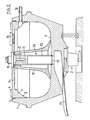
- FIG. 1 in section a container of a dimension according to the invention machine and Figure 2 shows a variant.
- FIG. 1 shows a container 1 and a vibration drive 2 known from the patent cited above.
- the container has a coreless base 3 which, in the present example, is slightly concave in the middle, that is to say with the drainage device, but also more concave (see FIG. 3 ⁇ ), may be flat or convex, as well as a cover 5 with handles 6, for example screwable on its circumference by means of a thread 4.
- the cover 5 has a circumferential bead 7 with a rounded inner surface 8.
- a core jacket 10 for example made of a low-abrasion plastic.
- the core jacket 10 has means for braking the bulk material, these means not being shown here, but in a parallel application by the same applicant. In this application it is described that these means can consist of ribs running in the circumferential direction or radial ribs or wing-like, radial ribs, or that the core jacket is of concave design and also that the side walls and the cover can also have a different shape.
- the core casing is held with play by a cylindrical center hub 11, which is hollow and also serves as a water inlet 12 or as an inlet for additives. The water inlet is connected to a rinse water connection 13 which is guided through the cover 5.
- the lid by means of a holder, as is described in the parallel patent application mentioned. It is important that the core jacket is largely independent of the container and therefore does not vibrate or only dampens it to a great extent. Since the kernmantle lifts off the floor during rinsing, the rinsing water can escape from the bottom of the tank. Likewise, compressed air can be in the Be guided inside the core jacket.
- the core jacket 10 allows the drain device 14 to be arranged in the middle of the bottom 3, that is to say under the core jacket.
- the adjustment of the locking pin 15 is not necessary as in the previously known example and can be carried out in such a way that even small and sensitive piece goods do not bump into the transition point between the container bottom and the pin, thereby eliminating the risk of injury.
- the locking pin 15 is moved up and down by means of a schematically illustrated adjustment mechanism 16, of course further adjustment mechanisms are possible and the locking pin can, for example, be tilted or retracted into the container bottom.
- the arrangement of the drain device in the bottom of the container enables simple and effective emptying of the bulk material. This makes it possible to collect and process the entire bulk material via a guide 17 in a mobile collecting device, during which the machine or its container can be quickly cleaned and loaded again.
- Such a container is suitable for the automatic loading and in particular automatic emptying of vibratory vibratory grinding machines and allows a significantly increased efficiency.
- the additives are not added via the water inlet but via an opening 9 with a screw cap which is offset from the center.
- An overflow 18 is attached to the top of the container wall in order to drain off the foam formed during processing.
- the locking pin 19 is also actuated not from below or from the side, but from above.
- the center hub 20 consists of a first piece 21 in which the flushing water outlet 12 is arranged, followed by a tube 22 to which the closure 19 is attached. It is possible as in the parallel application, the To fix the core jacket slidably, which makes an eccentric arrangement possible, and to move the core jacket in the opposite direction to the vibrations of the container.
- center hub with the water feedthrough can be arranged eccentrically, so that the core jacket can be displaced by rotation in such a way that the cross section of the grinding chamber can be changed.
- the drainage device can also be arranged offset, in which case the base part at this location is designed to be correspondingly concave, convex or flat, and the core jacket is arranged above it, that is to say also offset.
Landscapes
- Engineering & Computer Science (AREA)
- Mechanical Engineering (AREA)
- Finish Polishing, Edge Sharpening, And Grinding By Specific Grinding Devices (AREA)
- Grinding And Polishing Of Tertiary Curved Surfaces And Surfaces With Complex Shapes (AREA)
Abstract
Description
- Die vorliegende Erfindung bezieht sich auf eine Vibrationsgleitschleifmaschine, mit einem Behälter zur Aufnahme des Schüttgutes und einem Vibrationsantrieb. Solche Maschinen sind bekannt, beispielswise aus der CH-A-458 103 und CH-A 511 675. Solche Machinen weisen eine Vibratormulde auf, in welcher das Schüttgut, d.h. das zu bearbeitende Stückgut zusammen mit festem Trägermaterial und eventuellen Zusatzmitteln vibriert werden, um das Stückgut zu entgraten, glätten, schleifen und polieren. Ausserdem weist diese Maschine eine Ablassvorrichtung auf, die an der Seitenwand des Behälters angeordnet ist. Diese Ablassvorrichtung weist unter anderem einen Zapfen auf, der herausgeschraubt werden muss, falls man den Behälter entleeren will. Die genaue Einpassung dieses Zapfens an die gekrümmte Behälterwand ist recht schwierig und kostspielig, denn bei kleinsten Unebenheiten ist die Gefahr gross, dass kleines Stückgut daran hängen bleibt und verletzt wird. Ausserdem ist eine schnelle und vollständige Entleerung einer Kammer mit Kern schwierig durchzuführen. Andererseits ist es zur Erzielung einer wirksamen Bearbeitung von grossem Vorteil, dass der Behälter einen Kern aufweist und somit eine ringförmige Schleifkammer entsteht, in welcher das Schüttgut spiralförmig um den Kern bewegt wird.
- Es ist demgegenüber Aufgabe der vorliegenden Erfindung eine Vibrationsgleitschleifmaschine anzugeben, die eine wirksame Entleerung des Behälters gestattet und andererseits die Verletzungsgefahr von kleinem, empfindlichem Stückgut beseitigt. Eine solche Maschine wird in den Ansprüchen beschrieben.
- Die Erfindung wird im folgenden anhand einer Zeichnung von Ausführungsbeispielen näher erläutert, wobei Figur 1 im Schnitt einen Behälter einer erfindungsgemässen Ma schine und Figur 2 eine Ausführungsvariante darstellt.
- Figur 1 zeigt einen Behälter 1 und einen aus der oben zitierten Patentschrift bekannten Vibrationsantrieb 2. Der Behälter weist einen kernlosen Boden 3, der in vorliegendem Beispiel in der Mitte, das heisst bei der Ablassvorrichtung, leicht konkav ist, aber auch stärker konkav (siehe 3ʹ), eben oder konvex sein kann, sowie einen beispielsweise an seinem Umfang mittels eines Gewindes 4 schraubbaren Deckel 5 mit Griffen 6 auf. Der Dekkel 5 besitzt einen umlaufenden Wulst 7 mit abgerundeter Innenfläche 8.
- Im Mittelbereich des Bodens 3 befindet sich ein Kernmantel 10, beispielsweise aus einem abreibarmen Kunststoff. Der Kernmantel 10 weist Mittel zum Abbremsen des Schüttgutes auf, wobei diese Mittel hier nicht eingezeichnet sind, sondern in einer parallelen Anmeldung des gleichen Anmelders. In dieser Anmeldung ist beschrieben, dass diese Mittel aus in Umfangrichtung laufenden Rippen oder radialen Rippen oder flügelähnlichen, radialen Rippen bestehen können, oder dass der Kernmantel konkav gestaltet ist und ausserdem, dass auch die Seitenwände und der Deckel eine andere Gestalt aufweisen können. In vorliegendem Beispiel wird der Kernmantel von einer zylindrischen Zentrumsnabe 11 mit Spiel gehalten, die hohl ist und auch als Wassereinlass 12 oder als Einlass für Zusatzmittel dient. Der Wassereinlass ist mit einem Spülwasseranschluss 13 verbunden, der durch den Deckel 5 geführt ist. Es ist aber auch möglich, den Deckel mittels einer Halterung zu befestigen, wie dies in der erwähnten parallelen Patentanmeldung beschrieben ist. Wichtig ist, dass der Kernmantel weitgehend unabhängig vom Behälter ist und somit dessen Vibrationen nicht oder nur stark gedämpft ausführt. Da der Kernmantel sich bei der Spülung vom Boden abhebt, kann das Spülwasser am Behälterboden austreten. Desgleichen kann auch Druckluft in das Innere des Kernmantels geleitet werden. Der Kernmantel 10 erlaubt es, die Ablassvorrichtung 14 in der Mitte des Bodens 3 anzuordnen, das heisst unter dem Kernmantel. Das Anpassen des Verschlusszapfens 15 ist nicht nötig wie im vorbekannten Beispiel und kann derart ausgeführt sein, dass auch kleines und empfindliches Stückgut nicht an die Uebergangsstelle zwischen dem Behälterboden und dem Zapfen anstossen, wodurch die Verletzungsgefahr beseitigt wird. Der Verschlusszapfen 15 wird über einen schematisch dargestellten Verstellmechanismus 16 auf und ab bewegt, wobei selbstverständlich weitere Verstellmechanismen in Frage kommen und der Verschlusszapfen beispielsweise gekippt oder in den Behälterboden zurückgezogen werden kann. Die Anordnung der Ablassvorrichtung im Behälterboden ermöglicht eine einfache und wirksame Entleerung des Schüttgutes. Dadurch wird es möglich, das gesamte Schüttgut über eine Führung 17 in eine fahrbare Auffangvorrichtung aufzufangen und aufzuarbeiten, währenddessen die Maschine, beziehungsweise deren Behälter, schnell gereinigt und wieder geladen werden kann. Ein derartiger Behälter eignet sich für das automatische Beschicken und insbesondere automatische Entleeren von Vibrationsgleitschleifmaschinen und erlaubt einen wesentlich gesteigerten Wirkungsgrad.
- In der Ausführungsvariante gemäss Figur 2 werden die Zusatzmittel nicht über denWassereinlass sondern über eine gegenüber der Mitte versetzten Oeffnung 9 mit Schraubkappe beigegeben. An der Behälterwand ist oben ein Ueberlauf 18 angebracht, um den bei der Bearbeitung entstehenden Schaum abzulassen. In diesem Beispiel wird ferner der Verschlusszapfen 19 nicht von unten oder von der Seite, sondern von oben betätigt. Zu diesem Zwecke besteht die Zentrumsnabe 20 aus einem ersten Stück 21, in dem der Spülwasserauslass 12 angeordnet ist, gefolgt von einem Rohr 22, an dem der Verschluss 19 angebracht ist. Es ist wie in der Parallelanmeldung möglich, den Kernmantel verschiebbar zu befestigen, wodurch eine exzentrische Anordnung möglich ist, sowie den Kernmantel gegensinnig zu den Schwingungen des Behälters zu bewegen. Ausserdem kann die Zentrumsnabe mit der Wasserdurchführung exzentrisch angeordnet sein, so dass der Kernmantel durch Drehung derart verschoben werden kann, dass der Querschnitt der Schleifkammer veränderbar ist. Die Ablassvorrichtung kann ebenfalls versetzt angeordnet werden, wobei dann der Bodenteil an diesem Ort entsprechend konkav, konvex oder eben gestaltet und der Kernmantel darüber, das heisst ebenfalls versetzt, angeordnet wird.
Claims (10)
Priority Applications (3)
| Application Number | Priority Date | Filing Date | Title |
|---|---|---|---|
| DE8585810590T DE3567594D1 (en) | 1985-12-12 | 1985-12-12 | Vibrating grinding machine |
| EP85810590A EP0225418B1 (de) | 1985-12-12 | 1985-12-12 | Vibrationsgleitschleifmaschine |
| AT85810590T ATE40065T1 (de) | 1985-12-12 | 1985-12-12 | Vibrationsgleitschleifmaschine. |
Applications Claiming Priority (1)
| Application Number | Priority Date | Filing Date | Title |
|---|---|---|---|
| EP85810590A EP0225418B1 (de) | 1985-12-12 | 1985-12-12 | Vibrationsgleitschleifmaschine |
Publications (2)
| Publication Number | Publication Date |
|---|---|
| EP0225418A1 true EP0225418A1 (de) | 1987-06-16 |
| EP0225418B1 EP0225418B1 (de) | 1989-01-18 |
Family
ID=8194666
Family Applications (1)
| Application Number | Title | Priority Date | Filing Date |
|---|---|---|---|
| EP85810590A Expired EP0225418B1 (de) | 1985-12-12 | 1985-12-12 | Vibrationsgleitschleifmaschine |
Country Status (3)
| Country | Link |
|---|---|
| EP (1) | EP0225418B1 (de) |
| AT (1) | ATE40065T1 (de) |
| DE (1) | DE3567594D1 (de) |
Citations (2)
| Publication number | Priority date | Publication date | Assignee | Title |
|---|---|---|---|---|
| US3042322A (en) * | 1955-05-27 | 1962-07-03 | Nordberg Manufacturing Co | Rotating and gyrating ball mill |
| CH446100A (de) * | 1966-10-20 | 1967-10-31 | Schmid August | Vorrichtung zum Entgraten, Glätten und Polieren von Kleinteilen |
-
1985
- 1985-12-12 AT AT85810590T patent/ATE40065T1/de not_active IP Right Cessation
- 1985-12-12 DE DE8585810590T patent/DE3567594D1/de not_active Expired
- 1985-12-12 EP EP85810590A patent/EP0225418B1/de not_active Expired
Patent Citations (2)
| Publication number | Priority date | Publication date | Assignee | Title |
|---|---|---|---|---|
| US3042322A (en) * | 1955-05-27 | 1962-07-03 | Nordberg Manufacturing Co | Rotating and gyrating ball mill |
| CH446100A (de) * | 1966-10-20 | 1967-10-31 | Schmid August | Vorrichtung zum Entgraten, Glätten und Polieren von Kleinteilen |
Also Published As
| Publication number | Publication date |
|---|---|
| EP0225418B1 (de) | 1989-01-18 |
| ATE40065T1 (de) | 1989-02-15 |
| DE3567594D1 (en) | 1989-02-23 |
Similar Documents
| Publication | Publication Date | Title |
|---|---|---|
| DE1532683A1 (de) | Siebzentrifuge | |
| DE3142868A1 (de) | Fliehkraftbearbeitungsmaschine | |
| DE1428394A1 (de) | Geschirrspuelmaschine | |
| DE2602055A1 (de) | Fliehkrafttrommelmaschine zur oberflaechenbehandlung von kleinteilen | |
| DE3621050C2 (de) | Schwingmühle | |
| EP0268087A2 (de) | Vorrichtung zur Pflegebehandlung von Kontaktlinsen | |
| EP0225418B1 (de) | Vibrationsgleitschleifmaschine | |
| DE3143140A1 (de) | Bettfedern-waschmaschine | |
| EP0487946B1 (de) | Fliehkraftbearbeitungsmaschine | |
| DE2806331A1 (de) | Schwingzufuehrgeraet | |
| CH467651A (de) | Vibrator zum Entgraten, Glätten, Polieren und Mischen | |
| WO2001064394A1 (de) | Schleifmaschine | |
| DE2948691A1 (de) | Kontinuierlich arbeitende zentrifuge zum einmaischen und abschleudern von zuckerfuellmassen | |
| EP0712688A2 (de) | Entgratungs-, Satinier- und Poliermaschine mit Förderband-Antrieb | |
| DE2246155A1 (de) | Zentrifuge mit kontinuierlicher entleerung zum filtrieren von materialien beliebiger art, insbesondere von faserstoffen | |
| EP0029897A1 (de) | Ringtrogförmiger Vibrations-Scheuerbehälter | |
| DE2651099A1 (de) | Schwingzentrifuge zum entwaessern von feinkoernigem gut | |
| DE69200246T2 (de) | Auf einer Trägheitsplatte abgestützte Rotationsmaschine. | |
| DE19653377B4 (de) | Schubzentrifuge | |
| DE741995C (de) | Wasch- und Schleudermaschine fuer Waesche | |
| EP0225417A1 (de) | Vibrationsgleitschleifmaschine | |
| DE2856763A1 (de) | Saatgutbeizapparat | |
| JP4153126B2 (ja) | スクリュー式脱水機 | |
| EP1259353B1 (de) | Schleifmaschine | |
| DE1288947B (de) | Austrags- und Trenneinrichtung fuer Werkstuecke bzw. Schleifmittel an Vibrations-Scheuerbehaeltern |
Legal Events
| Date | Code | Title | Description |
|---|---|---|---|
| PUAI | Public reference made under article 153(3) epc to a published international application that has entered the european phase |
Free format text: ORIGINAL CODE: 0009012 |
|
| 17P | Request for examination filed |
Effective date: 19861108 |
|
| AK | Designated contracting states |
Kind code of ref document: A1 Designated state(s): AT BE CH DE FR GB IT LI LU NL SE |
|
| RBV | Designated contracting states (corrected) |
Designated state(s): AT CH DE FR GB IT LI |
|
| 17Q | First examination report despatched |
Effective date: 19871022 |
|
| ITF | It: translation for a ep patent filed | ||
| GRAA | (expected) grant |
Free format text: ORIGINAL CODE: 0009210 |
|
| AK | Designated contracting states |
Kind code of ref document: B1 Designated state(s): AT CH DE FR GB IT LI |
|
| REF | Corresponds to: |
Ref document number: 40065 Country of ref document: AT Date of ref document: 19890215 Kind code of ref document: T |
|
| GBT | Gb: translation of ep patent filed (gb section 77(6)(a)/1977) | ||
| REF | Corresponds to: |
Ref document number: 3567594 Country of ref document: DE Date of ref document: 19890223 |
|
| ET | Fr: translation filed | ||
| PLBE | No opposition filed within time limit |
Free format text: ORIGINAL CODE: 0009261 |
|
| STAA | Information on the status of an ep patent application or granted ep patent |
Free format text: STATUS: NO OPPOSITION FILED WITHIN TIME LIMIT |
|
| 26N | No opposition filed | ||
| ITTA | It: last paid annual fee | ||
| PGFP | Annual fee paid to national office [announced via postgrant information from national office to epo] |
Ref country code: GB Payment date: 19921109 Year of fee payment: 8 |
|
| PGFP | Annual fee paid to national office [announced via postgrant information from national office to epo] |
Ref country code: AT Payment date: 19921230 Year of fee payment: 8 |
|
| PGFP | Annual fee paid to national office [announced via postgrant information from national office to epo] |
Ref country code: FR Payment date: 19931129 Year of fee payment: 9 |
|
| PG25 | Lapsed in a contracting state [announced via postgrant information from national office to epo] |
Ref country code: GB Effective date: 19931212 Ref country code: AT Effective date: 19931212 |
|
| PGFP | Annual fee paid to national office [announced via postgrant information from national office to epo] |
Ref country code: DE Payment date: 19931214 Year of fee payment: 9 |
|
| PGFP | Annual fee paid to national office [announced via postgrant information from national office to epo] |
Ref country code: CH Payment date: 19931227 Year of fee payment: 9 |
|
| GBPC | Gb: european patent ceased through non-payment of renewal fee |
Effective date: 19931212 |
|
| PG25 | Lapsed in a contracting state [announced via postgrant information from national office to epo] |
Ref country code: LI Effective date: 19941231 Ref country code: CH Effective date: 19941231 |
|
| PG25 | Lapsed in a contracting state [announced via postgrant information from national office to epo] |
Ref country code: FR Effective date: 19950831 |
|
| REG | Reference to a national code |
Ref country code: CH Ref legal event code: PL |
|
| PG25 | Lapsed in a contracting state [announced via postgrant information from national office to epo] |
Ref country code: DE Effective date: 19950901 |
|
| REG | Reference to a national code |
Ref country code: FR Ref legal event code: ST |