EP0222382B1 - Procédé de réglage de turbocompresseurs - Google Patents
Procédé de réglage de turbocompresseurs Download PDFInfo
- Publication number
- EP0222382B1 EP0222382B1 EP86115702A EP86115702A EP0222382B1 EP 0222382 B1 EP0222382 B1 EP 0222382B1 EP 86115702 A EP86115702 A EP 86115702A EP 86115702 A EP86115702 A EP 86115702A EP 0222382 B1 EP0222382 B1 EP 0222382B1
- Authority
- EP
- European Patent Office
- Prior art keywords
- controller
- function
- varied
- differential
- signal
- Prior art date
- Legal status (The legal status is an assumption and is not a legal conclusion. Google has not performed a legal analysis and makes no representation as to the accuracy of the status listed.)
- Expired - Lifetime
Links
Images

Classifications
-
- F—MECHANICAL ENGINEERING; LIGHTING; HEATING; WEAPONS; BLASTING
- F04—POSITIVE - DISPLACEMENT MACHINES FOR LIQUIDS; PUMPS FOR LIQUIDS OR ELASTIC FLUIDS
- F04D—NON-POSITIVE-DISPLACEMENT PUMPS
- F04D27/00—Control, e.g. regulation, of pumps, pumping installations or pumping systems specially adapted for elastic fluids
- F04D27/02—Surge control
- F04D27/0207—Surge control by bleeding, bypassing or recycling fluids
Definitions
- the invention relates to a method for regulating turbo compressors of the type specified in the preamble of claim 1.
- the method according to the invention is particularly suitable for the so-called point limit control for preventing the pumping of a compressor. But this can also apply to other regulations such as Anti-choke control, turbine speed control, etc. can be used.
- a method of the type mentioned for the surge limit control is known from the publication 'Turbolog- the electronic control system for GHH turbomachinery' in News for Mechanical Engineering No. 3, May 82 and also from US Pat. No. 4,142,838
- the type mentioned, in which the differentiation is realized by subtracting the delayed signal from the undelayed signal, is also known from DE-PS 28 28 124.
- Pumping is understood to mean an unstable behavior of a turbocompressor, in which the delivery medium intermittently or periodically from the pressure side This behavior occurs when the throughput or the pressure ratio between the compressor inlet and outlet is too low.
- the so-called surge limit line separates the stable from the unstable area in the characteristic map of the compressor.
- the surge limit control ensures that when the current operating point approaches the Surge line or one at a safety distance parallel to di a blow-off or blow-off valve at the compressor outlet is opened.
- this method it is also known to change the control behavior of the controller which generates the control signal for the blow-off valve as a function of the position of the operating point in that the control gain is increased non-linearly when the blow-off line is exceeded.
- controllers With controls of this type, the use of controllers with a control component that differentiates the input signal encounters various difficulties.
- One of these difficulties is the fact that an actual signal, which is derived from the flow, has a very high superimposed noise level and is therefore difficult to differentiate. This difficulty is less pronounced if the actual value signal is derived from the final pressure.
- the invention is based on the object of developing a method of the type specified so that it offers the possibility of a control with differential behavior which is effective and precisely in the vicinity of the surge line and is as insensitive as possible to noise.
- the advantage is achieved that the differentiating effect can be increased in a targeted manner when the working point is close to the surge line, so that even small changes in the actual value signal can lead to a rapid response of the controller.
- the advantage is achieved that the differentiating effect can be used selectively when the working point approaches the surge limit line, that is to say in the “dangerous” direction.
- the pressure difference in front of and behind a throttle orifice is detected on the intake side of a compressor K by a first actual value transmitter 1, which pressure is simultaneously a measure of the intake volume flow or the compressor throughput.
- the final pressure P 2 at the compressor outlet is detected by a second actual value transmitter 3.
- a computer 11 with associated memory 13 uses the actual values to form the coordinates of the working point in the map determined by the throughput and the final pressure / suction pressure ratio and compares them with a stored blow-off line A specified in the map. In general, the final and suction pressure must be recorded will. To simplify matters, however, it can be assumed that the suction pressure is constant and is therefore not constantly measured.
- a setpoint signal for the flow is generated, which is compared with the actual value in the subtractor 5 and an input signal for a controller 7 is formed therefrom.
- the controller 7 has a proportional part 7a, a differential part 7b and an integral part 7c.
- the controller output variable serves as a control signal for a relief valve 9 at the compressor outlet.
- the slope of the compressor characteristic curve K constant speed and / or constant blade position, or also stored constant throttle position in the inlet.
- a control element On the value of the slope of the compressor characteristic curve belonging to the current operating point, a control element generates a control signal, by means of which the time constant To effective for the differentiation in the differential part 7b is changed, in such a way that the differentiating effect of the time constant is proportional to the increase in the compressor characteristic curve. This ensures that the differential portion of the controller 7 has approximately the same effectiveness in the entire characteristic.
- the differentiating time constant T D can also be varied depending on the distance of the current working point from the blow-off line, again in such a way that the differentiating effect is increased with a decreasing distance between the blow-off line and the working point and vice versa.
- the size of the differentiating effect i.e. the proportion of the differential part 7b compared to the proportional part 7a and integral part 7c of the controller can be changed.
- the size of the differentiating effect can be adjusted depending on the slope of the blow-off line or the value of the final pressure. It is also possible to switch the differential component 7b on or off depending on a limit value in the controller output. E.g. the differential component 7b can be switched off when the controller output signal 100% or the control difference reaches another predetermined value which corresponds to a certain distance from the blow-off line.
- the differential portion 7b of the controller can also be designed to move in one direction, e.g. is effective when the input signal rises, that is to say can only emit a positive but not a negative output signal.
- the differentiation time constant does not need to be controlled exactly in accordance with the actual slope of the characteristic curve. Rather, simplifications are possible.
- a simplification results when the slope of the characteristic curves depends on one of the map coordinates, that is to say on the pressure or on the flow, and the characteristic curves are only shifted parallel to larger flows or pressures. This is the case when the characteristic curves 2 open relatively steeply into the surge limit in the area of lower speeds or guide vane positions, but flatter in the upper area. Even if the characteristic curves are not completely congruent, in many cases an approximation by parallel displacement of a characteristic curve is permissible.
- the slope of the characteristic curve and thus the size of the differentiation time constant To depends only on the pressure P or pressure flow Vab.
- the course of the characteristic curve can either be stored in a digital memory or can also be predefined analogously in a function generator 14, which is indicated by dashed lines in the drawing.
- the input of this function generator is the pressure, the output directly the size To.
- the function is not ideally reproduced in the function generator, but in an approximation by straight line sections.
- the simplest case is a straight line consisting of two sections. This can be realized very simply by switching the value for T D to another value from a predetermined pressure.
- the function generator 14 delivering the variable To can be adjusted depending on the control difference applied to the subtractor 5.
- simplifications are also possible for this function generator, starting with a simple switchover of the size T D between two values over several straight line sections up to a polyline.
- the position of the operating point is determined by detecting the final pressure and the throughput
- other variables such as the pressure ratio between final and suction pressure, the speed, the guide vane position can also be used for determining the working point or for defining the map , the power, the input signal of the controller or the output signal of a process controller can be used.
- the map can be determined by other parameters, such as the adiabatic delivery head and the intake volume flow are determined. In any case, the surge line has a clear course in the map.
- a variant is described below in which the differentiating effect of the controller is also influenced, but not by changing the time constant, but by adding further function blocks.
- the variant described here is particularly suitable for controls in which one of the input signals has signal noise, i.e. a high-frequency, low-amplitude noise signal is superimposed on the input signal. A direct differentiation of this input signal could therefore under certain circumstances result in the noise signal being amplified considerably.
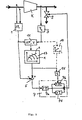
- FIG. 2 shows a modified PID controller in which the suppression of the differentiating effect in the undesired direction is achieved by introducing a limiter 19 at the output of the differentiating element 7b.
- the limiter 19 is designed in such a way that only the signals of the differentiating element which cause the operating point to be shifted in the direction of the stability range are passed.
- a one-way retarder 17 can be inserted in front of the differentiating element.
- the one-way retarder is a component whose output signal initially follows the input signal in one direction (e.g. in the direction of falling signals) without delay until the input signal reaches a relative minimum.
- a subsequent rise in the input signal even if it occurs quickly, leads to a relatively slow rise in the output signal, the rise rate being determined by a predefined, possibly adjustable time constant.
- the output signal of the delay 17 follows the input signal in this direction only with a delay. As soon as the input signal reaches the signal level of the output signal again, the output signal follows the input signal until a new minimum value is assumed.
- the output signal of the delay 17 thus always remains at or in the vicinity of the smallest input value.
- the remaining noise component is significantly reduced by this arrangement, since only short-term signal changes that always occur when the input variable assumes a new, even smaller minimum value are passed on to the differentiating circuit.
- the delay 17 has a finite time constant in the direction of increasing signals in order to give the system the opportunity to return to normal after reaching an extreme minimum value once or to track the output of the delay 17 as the useful signal increases.
- the differentiator 7b can be followed by the limiter 19 already mentioned.
- the dead time element 17 has the effect that only the signals whose signal lengths exceed the dead time are passed on.
- Two alternatives are provided for the design of the dead time element 21: In the first alternative, the signal is blocked for the duration of the dead time and only then passed on to the output without delay. In the second alternative, the signal is passed on delayed by the dead time if it has been present at the input during the entire dead time. This has the advantage that the signal curve of the differentiating element is not lost during the dead time, but is added to the manipulated variable delayed by the dead time.
Claims (13)
Applications Claiming Priority (2)
| Application Number | Priority Date | Filing Date | Title |
|---|---|---|---|
| DE3540087 | 1985-11-12 | ||
| DE19853540087 DE3540087A1 (de) | 1985-11-12 | 1985-11-12 | Verfahren zum regeln von turbokompressoren |
Publications (3)
| Publication Number | Publication Date |
|---|---|
| EP0222382A2 EP0222382A2 (fr) | 1987-05-20 |
| EP0222382A3 EP0222382A3 (en) | 1988-01-13 |
| EP0222382B1 true EP0222382B1 (fr) | 1990-09-26 |
Family
ID=6285760
Family Applications (1)
| Application Number | Title | Priority Date | Filing Date |
|---|---|---|---|
| EP86115702A Expired - Lifetime EP0222382B1 (fr) | 1985-11-12 | 1986-11-12 | Procédé de réglage de turbocompresseurs |
Country Status (4)
| Country | Link |
|---|---|
| US (1) | US4810163A (fr) |
| EP (1) | EP0222382B1 (fr) |
| JP (1) | JPS62113890A (fr) |
| DE (2) | DE3540087A1 (fr) |
Cited By (1)
| Publication number | Priority date | Publication date | Assignee | Title |
|---|---|---|---|---|
| DE10001365A1 (de) * | 2000-01-14 | 2001-07-19 | Man Turbomasch Ag Ghh Borsig | Verfahren und Einrichtung zum Regeln eines Turbokompressors zur Verhinderung des Pumpens |
Families Citing this family (8)
| Publication number | Priority date | Publication date | Assignee | Title |
|---|---|---|---|---|
| DE3805119A1 (de) * | 1988-02-18 | 1989-08-31 | Gutehoffnungshuette Man | Verfahren und einrichtung zum regeln von turbokompressoren |
| DE3809070A1 (de) * | 1988-03-18 | 1989-10-26 | Gutehoffnungshuette Man | Verfahren zum sicheren betreiben von turbo-kompressoren |
| DE3811230A1 (de) * | 1988-04-02 | 1989-10-26 | Gutehoffnungshuette Man | Verfahren zum schuetzen eines turboverdichters vor pumpen mittels abblasens ueber ein abblaseventil sowie vorrichtung zur durchfuehrung des verfahrens |
| IT1255836B (it) * | 1991-10-01 | 1995-11-17 | Procedimento per la sorveglianza del limite di pompaggio di turbocompressori a piu' stadi e refrigerazione intermedia | |
| US5599161A (en) * | 1995-11-03 | 1997-02-04 | Compressor Controls Corporation | Method and apparatus for antisurge control of multistage compressors with sidestreams |
| DE19541192C2 (de) * | 1995-11-04 | 1999-02-04 | Ghh Borsig Turbomaschinen Gmbh | Verfahren zum Schutz eines Turbokompressors vor Betrieb im instabilen Arbeitsbereich mittels einer Abblaseeinrichtung |
| DE10144018A1 (de) * | 2001-09-07 | 2003-03-27 | Linde Ag | Verfahren zum Regeln eines Verdichtersatzes |
| DE10304063A1 (de) * | 2003-01-31 | 2004-08-12 | Man Turbomaschinen Ag | Verfahren zum sicheren Betreiben von Turbokompressoren mit einer Pumpgrenzregelung und einem Pumpgrenzregelventil |
Citations (1)
| Publication number | Priority date | Publication date | Assignee | Title |
|---|---|---|---|---|
| DE2828124A1 (de) * | 1978-06-27 | 1980-01-10 | Gutehoffnungshuette Sterkrade | Verfahren zur verhinderung des pumpens von turboverdichtern |
Family Cites Families (13)
| Publication number | Priority date | Publication date | Assignee | Title |
|---|---|---|---|---|
| DE2623899B2 (de) * | 1976-05-28 | 1979-11-29 | Gutehoffnungshuette Sterkrade Ag, 4200 Oberhausen | Verfahren zum Betreiben von Turboverdichtern in der Nähe der Pumpgrenze |
| US4139328A (en) * | 1977-05-25 | 1979-02-13 | Gutehoffnungshitte Sterkrade Ag | Method of operating large turbo compressors |
| DE2735246C2 (de) * | 1977-08-04 | 1985-07-18 | Siemens AG, 1000 Berlin und 8000 München | Regeleinrichtung für einen Turboverdichter |
| DE2739229C3 (de) * | 1977-08-31 | 1980-07-10 | Siemens Ag, 1000 Berlin Und 8000 Muenchen | Regeleinrichtung für einen Turboverdichter |
| US4142838A (en) * | 1977-12-01 | 1979-03-06 | Compressor Controls Corporation | Method and apparatus for preventing surge in a dynamic compressor |
| DE2812820C2 (de) * | 1978-01-31 | 1986-04-03 | BBC Aktiengesellschaft Brown, Boveri & Cie., Baden, Aargau | Regeleinrichtung für eine Dampfturbine |
| DE2852717C2 (de) * | 1978-12-06 | 1982-02-11 | M.A.N. Maschinenfabrik Augsburg-Nürnberg AG, 4200 Oberhausen | Verfahren zur Enddruckbegrenzung für Turbo-Verdichter mittels Abblaseregelung |
| DE3105376C2 (de) * | 1981-02-14 | 1984-08-23 | M.A.N. Maschinenfabrik Augsburg-Nürnberg AG, 4200 Oberhausen | Verfahren zum Betreiben von Turboverdichtern |
| US4640665A (en) * | 1982-09-15 | 1987-02-03 | Compressor Controls Corp. | Method for controlling a multicompressor station |
| US4560319A (en) * | 1983-08-01 | 1985-12-24 | MAN Maschinenfabrik Unternehmensbereich GHH Sterkrade | Method and apparatus for controlling at least two parallel-connected turbocompressors |
| US4562531A (en) * | 1983-10-07 | 1985-12-31 | The Babcock & Wilcox Company | Integrated control of output and surge for a dynamic compressor control system |
| US4627788A (en) * | 1984-08-20 | 1986-12-09 | The Babcock & Wilcox Company | Adaptive gain compressor surge control system |
| US4586870A (en) * | 1984-05-11 | 1986-05-06 | Elliott Turbomachinery Co., Inc. | Method and apparatus for regulating power consumption while controlling surge in a centrifugal compressor |
-
1985
- 1985-11-12 DE DE19853540087 patent/DE3540087A1/de not_active Withdrawn
-
1986
- 1986-10-29 US US06/924,858 patent/US4810163A/en not_active Expired - Lifetime
- 1986-11-11 JP JP61266826A patent/JPS62113890A/ja active Pending
- 1986-11-12 DE DE8686115702T patent/DE3674540D1/de not_active Expired - Fee Related
- 1986-11-12 EP EP86115702A patent/EP0222382B1/fr not_active Expired - Lifetime
Patent Citations (1)
| Publication number | Priority date | Publication date | Assignee | Title |
|---|---|---|---|---|
| DE2828124A1 (de) * | 1978-06-27 | 1980-01-10 | Gutehoffnungshuette Sterkrade | Verfahren zur verhinderung des pumpens von turboverdichtern |
Non-Patent Citations (1)
| Title |
|---|
| DE-Publikation "Turbolog- Das elektronische Regelsystem für GHH- Turbomaschinen"- Sonderdruck aus Nachrichten für den Maschinenbau 5/82 * |
Cited By (1)
| Publication number | Priority date | Publication date | Assignee | Title |
|---|---|---|---|---|
| DE10001365A1 (de) * | 2000-01-14 | 2001-07-19 | Man Turbomasch Ag Ghh Borsig | Verfahren und Einrichtung zum Regeln eines Turbokompressors zur Verhinderung des Pumpens |
Also Published As
| Publication number | Publication date |
|---|---|
| DE3540087A1 (de) | 1987-05-14 |
| EP0222382A3 (en) | 1988-01-13 |
| JPS62113890A (ja) | 1987-05-25 |
| DE3674540D1 (de) | 1990-10-31 |
| EP0222382A2 (fr) | 1987-05-20 |
| US4810163A (en) | 1989-03-07 |
Similar Documents
| Publication | Publication Date | Title |
|---|---|---|
| DE2909825C2 (de) | Vorrichtung zur Einstellung des Anstellwinkels der Verdichterleitschaufeln eines Gasturbinentriebwerks | |
| DE69728254T2 (de) | Regelsystem für dynamische kompressoren zur verhinderung des wiederauftretens des pumpens | |
| DE2828124C2 (de) | Verfahren zur Verhinderung des Pumpens von Turboverdichtern | |
| DE3105376C2 (de) | Verfahren zum Betreiben von Turboverdichtern | |
| EP0222382B1 (fr) | Procédé de réglage de turbocompresseurs | |
| EP0336095B1 (fr) | Procédé de commande pour éviter le pompage d'un compresseur centrifuge par l'échappement suivant les besoins | |
| DE19828368C2 (de) | Verfahren und Vorrichtung zum Betreiben von zwei- oder mehrstufigen Verdichtern | |
| EP0254029A2 (fr) | Procédé de filtrage d'un signal brouillé | |
| EP0223207B1 (fr) | Procédé et dispositif de réglage d'un turbocompresseur pour empêcher le pompage | |
| EP0223208B1 (fr) | Procédé et dispositif de réglage de turbocompresseurs | |
| EP0332888B1 (fr) | Procédé pour faire fonctionner des compresseurs centrifuges | |
| EP0335105B1 (fr) | Procédé pour éviter le pompage d'un compresseur centrifuge par le contrôle d'échappement | |
| EP1116885B1 (fr) | Procédé et appareil de contrôle d'un turbo-compresseur pour éviter le pompage | |
| EP0334034B1 (fr) | Procédé de commande pour éviter le pompage d'un compresseur centrifuge | |
| DE2623899A1 (de) | Verfahren zum betreiben von grossen turbo-verdichtern | |
| EP0336092A2 (fr) | Procédé de protection d'un compresseur centrifuge contre le pompage par une valve d'échappement et le dispositif pour réaliser ce procédé | |
| EP0757180B1 (fr) | Procédé et dispositif d'opération des turbomachines avec régulateurs à gain proportionnel élevé | |
| DE2735246A1 (de) | Regeleinrichtung fuer einen turboverdichter | |
| DE2739229A1 (de) | Regeleinrichtung fuer einen turboverdichter | |
| DE1920193A1 (de) | Druckregler | |
| DE2045782B2 (de) | Brennstoffregeleinrichtung für ein Gasturbinentriebwerk | |
| DE3346633C1 (de) | Verfahren zur Pumpgrenzregelung von Axialventilatoren | |
| DE1673542C3 (de) | Elektrische Regeleinrichtung | |
| DE3149488A1 (de) | Verfahren zur automatischen verringerung der positionsnacheilung eines nicht-linearen stellglieds | |
| DE2542936B2 (de) | Drehzahl-regelsystem fuer eine dampfturbine |
Legal Events
| Date | Code | Title | Description |
|---|---|---|---|
| PUAI | Public reference made under article 153(3) epc to a published international application that has entered the european phase |
Free format text: ORIGINAL CODE: 0009012 |
|
| AK | Designated contracting states |
Kind code of ref document: A2 Designated state(s): CH DE FR GB IT LI NL |
|
| PUAL | Search report despatched |
Free format text: ORIGINAL CODE: 0009013 |
|
| AK | Designated contracting states |
Kind code of ref document: A3 Designated state(s): CH DE FR GB IT LI NL |
|
| 17P | Request for examination filed |
Effective date: 19880527 |
|
| RAP1 | Party data changed (applicant data changed or rights of an application transferred) |
Owner name: MAN GUTEHOFFNUNGSHUETTE AKTIENGESELLSCHAFT |
|
| 17Q | First examination report despatched |
Effective date: 19890406 |
|
| ITF | It: translation for a ep patent filed |
Owner name: UFFICIO TECNICO ING. A. MANNUCCI |
|
| GRAA | (expected) grant |
Free format text: ORIGINAL CODE: 0009210 |
|
| AK | Designated contracting states |
Kind code of ref document: B1 Designated state(s): CH DE FR GB IT LI NL |
|
| ET | Fr: translation filed | ||
| REF | Corresponds to: |
Ref document number: 3674540 Country of ref document: DE Date of ref document: 19901031 |
|
| GBT | Gb: translation of ep patent filed (gb section 77(6)(a)/1977) | ||
| PLBE | No opposition filed within time limit |
Free format text: ORIGINAL CODE: 0009261 |
|
| STAA | Information on the status of an ep patent application or granted ep patent |
Free format text: STATUS: NO OPPOSITION FILED WITHIN TIME LIMIT |
|
| 26N | No opposition filed | ||
| ITTA | It: last paid annual fee | ||
| REG | Reference to a national code |
Ref country code: GB Ref legal event code: 732E |
|
| REG | Reference to a national code |
Ref country code: CH Ref legal event code: PUE Owner name: MAN GUTEHOFFNUNGSHUETTE AKTIENGESELLSCHAFT -DANN A |
|
| NLS | Nl: assignments of ep-patents |
Owner name: GHH BORSIG TURBOMASCHINEN GMBH |
|
| REG | Reference to a national code |
Ref country code: FR Ref legal event code: TP |
|
| PGFP | Annual fee paid to national office [announced via postgrant information from national office to epo] |
Ref country code: GB Payment date: 19991012 Year of fee payment: 14 |
|
| PGFP | Annual fee paid to national office [announced via postgrant information from national office to epo] |
Ref country code: NL Payment date: 19991014 Year of fee payment: 14 Ref country code: CH Payment date: 19991014 Year of fee payment: 14 |
|
| PGFP | Annual fee paid to national office [announced via postgrant information from national office to epo] |
Ref country code: DE Payment date: 19991025 Year of fee payment: 14 |
|
| PGFP | Annual fee paid to national office [announced via postgrant information from national office to epo] |
Ref country code: FR Payment date: 19991027 Year of fee payment: 14 |
|
| PG25 | Lapsed in a contracting state [announced via postgrant information from national office to epo] |
Ref country code: GB Free format text: LAPSE BECAUSE OF NON-PAYMENT OF DUE FEES Effective date: 20001112 |
|
| PG25 | Lapsed in a contracting state [announced via postgrant information from national office to epo] |
Ref country code: LI Free format text: LAPSE BECAUSE OF NON-PAYMENT OF DUE FEES Effective date: 20001130 Ref country code: CH Free format text: LAPSE BECAUSE OF NON-PAYMENT OF DUE FEES Effective date: 20001130 |
|
| PG25 | Lapsed in a contracting state [announced via postgrant information from national office to epo] |
Ref country code: NL Free format text: LAPSE BECAUSE OF NON-PAYMENT OF DUE FEES Effective date: 20010601 |
|
| GBPC | Gb: european patent ceased through non-payment of renewal fee |
Effective date: 20001112 |
|
| REG | Reference to a national code |
Ref country code: CH Ref legal event code: PL |
|
| PG25 | Lapsed in a contracting state [announced via postgrant information from national office to epo] |
Ref country code: FR Free format text: LAPSE BECAUSE OF NON-PAYMENT OF DUE FEES Effective date: 20010731 |
|
| NLV4 | Nl: lapsed or anulled due to non-payment of the annual fee |
Effective date: 20010601 |
|
| PG25 | Lapsed in a contracting state [announced via postgrant information from national office to epo] |
Ref country code: DE Free format text: LAPSE BECAUSE OF NON-PAYMENT OF DUE FEES Effective date: 20010801 |
|
| REG | Reference to a national code |
Ref country code: FR Ref legal event code: ST |
|
| REG | Reference to a national code |
Ref country code: FR Ref legal event code: CJ Ref country code: FR Ref legal event code: CD Ref country code: FR Ref legal event code: CA |
|
| PG25 | Lapsed in a contracting state [announced via postgrant information from national office to epo] |
Ref country code: IT Free format text: LAPSE BECAUSE OF NON-PAYMENT OF DUE FEES;WARNING: LAPSES OF ITALIAN PATENTS WITH EFFECTIVE DATE BEFORE 2007 MAY HAVE OCCURRED AT ANY TIME BEFORE 2007. THE CORRECT EFFECTIVE DATE MAY BE DIFFERENT FROM THE ONE RECORDED. Effective date: 20051112 |